• 검색 결과가 없습니다.

An Indoor Broadcasting System Using Light-Emitting Diode Lamps Coupled with Power Line

N/A
N/A
Protected

Academic year: 2021

Share "An Indoor Broadcasting System Using Light-Emitting Diode Lamps Coupled with Power Line"

Copied!
6
0
0

로드 중.... (전체 텍스트 보기)

전체 글

(1)

http://dx.doi.org/10.5369/JSST.2015.24.5.342 pISSN 1225-5475/eISSN 2093-7563

An Indoor Broadcasting System Using Light-Emitting Diode Lamps Coupled with Power Line

Seong-Ho Lee

+

Abstract

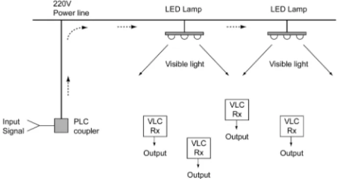
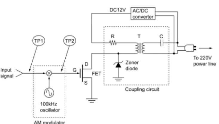
We introduce an indoor broadcasting system using light-emitting diode (LED) lamps coupled with a 220 V power line. Two couplers connected to the power line constitute a power line communication (PLC) link. The transmission path from an LED lamp to a pho- todetector forms a visible light communication (VLC) link in free space. When the LED lamp is coupled to the power line, a composite PLC-VLC link is formed, making it possible to transmit a VLC signal beyond line-of-sight. In experiments, a 4 kHz analog signal mod- ulated with a 100 kHz carrier was sent to the power line by a PLC coupler, and LED lamps coupled to the power line detected the signal and radiated it to multiple VLC receivers in the room. This configuration is useful in expanding an indoor VLC sensor network to adja- cent rooms or constructing a voice broadcasting system in a building or apartments with existing power lines.

Keywords: LED lamp, Visible light communication, Power line communication, Sensor network, Indoor broadcasting

1. INTRODUCTION

Recently there have been great advances in the fabrication of light-emitting diodes (LEDs) and high-power visible LEDs, which are replacing conventional illumination devices such as fluorescent lamps and incandescent lamps in offices, on streets, and in apartments. LEDs have advantages such as long lifetime, high efficiency, and small size. In addition, due to their high-speed modulation capabilities, visible LEDs have been widely used as light sources in visible light communication (VLC) in which illumination and communication are carried out simultaneously [1-4]. VLC is a wireless optical communication method in which optical signals are directly transmitted from light sources to photodetectors through free space. However, because the light signal is transmitted in the line-of-sight range, if there is an obstacle between a transmitter and a receiver, the VLC link can be blocked.

To overcome this problem, VLC systems can be coupled to

power line communication (PLC) systems. For years now, PLC systems have been developed to facilitate home automation technologies. At the transmitter of a PLC system, the base band input signal is modulated with a carrier frequency that is much higher than the power line frequency; it is then transferred to the power line using a PLC coupler. At the receiver side of the PLC system, the transmitted signal is extracted by another PLC coupler and demodulated to recover the base band signal. Because the modulation and demodulation schemes in VLC and PLC systems are similar, the two systems can be easily combined to constitute PLC-VLC links. When VLC systems are incorporated into power lines, signal transmission is not restricted to the line-of-sight range and can thus be increased to a much wider area.

In this paper, we introduce a VLC system combined with a PLC system that can be used for expanding VLC links to a wide area beyond line-of-sight, such as to an adjacent room. It can also be used to construct an indoor broadcasting system in a large room, such as for an auditorium. In constructing PLC-VLC links, we should consider the effects of environmental optical noise, LED light flickering, and noise induction from the power line.

Because VLC systems use free space for transmission media, VLC systems can be subjected to interference by the light noise from conventional illuminating devices such as fluorescent lamps or incandescent lamps [5,6]. In order to eliminate environmental noise effects, transmission signals can be modulated using a carrier frequency that is much higher than 120 Hz, which is the main noise frequency component from conventional illumination Department of Electronics & IT Media Engineering, Seoul National University

of Science and Technology

232 Gongneung-ro, Nowon-gu, Seoul 139-743, Korea

+

Corresponding author: [email protected]

(Received: Jul. 6, 2015, Revised: Sep. 15, 2015, Accepted: Sep. 17, 2015)

This is an Open Access article distributed under the terms of the Creative Commons Attribution Non-Commercial License(http://creativecommons.org/

licenses/bync/3.0) which permits unrestricted non-commercial use, distribution,

and reproduction in any medium, provided the original work is properly cited.

(2)

devices.

In VLC systems, the average power of an LED light should not change during data transmission, which can be the cause of flickering of LED lamps and affect the illumination condition.

Modulation with a high carrier frequency prevents the flickering of LED lamps because the average power is not changed by the modulated signal and human eyes do not detect high-frequency components. Experimentally, we observed that human eyes do not detect light intensity variations with a frequency of 100 Hz or higher.

In PLC systems, the signal should be far from the power line frequency of 60 Hz. In order to prevent the power line frequency or power line noise from being induced in signal channels, the base band signal is modulated with a carrier frequency that is much higher than the power line frequency [7].

In an experiment of analog signal transmission via a PLC-VLC link, we used amplitude modulation (AM) with a 100 kHz carrier in order to prevent environmental noise, LED flickering, and power line frequency induction. The same PLC-VLC link was also used for digital signal transmission with amplitude shift keying (ASK) modulation. Because we used the same modulation schemes in PLC and VLC links, the two different links could be directly connected to each other for signal transmission.

This configuration can be easily applied to the construction of indoor broadcasting systems by simply adding PLC couplers and LED lamps to existing power lines in offices or buildings.

2. SYSTEM CONFIGURATION

The overall system configuration for an indoor broadcasting system using a PLC-VLC link is shown in Fig. 1.

An input signal is applied to a PLC coupler. It then propagates along the power line to the LED lamps. Because each LED lamp has its own PLC coupler in the driving circuit, each lamp receives the signal from the power line, transforms the electrical signal to visible light, and radiates it toward VLC receivers in the room. A VLC receiver detects the VLC signal from the LED lamps, transforms it to electrical signal, and recovers the input signal transmitted by the PLC coupler at the input port. The transmission path in the overall system can be grouped into two links; PLC and VLC links, as shown in Fig. 2.

A PLC coupler at the input port and a coupling circuit on the front of the LED lamp constitute a PLC link (from TP1 to TP3 in Fig. 2). In the input PLC coupler, an AM modulator shifts the signal spectrum to a carrier frequency band that is much

higher than the power line frequency of 60 Hz. The output signal of the AM modulator is then sent to the 220 V power line by the coupling circuit in the PLC coupler. The AM signal propagates along the power line and arrives at the LED lamp.

The coupling circuit in the LED lamp captures the AM signal in the power line and transfers it to an LED array through a driving circuit.

An LED array in the LED lamp and a VLC receiver constitute a VLC link (from TP3 to TP5 in Fig. 2). The LED array transforms the electrical AM signal to an optical signal and radiates it to free space. A photodetector in the VLC receiver detects the optical signal from the LED lamp, changes the optical signal to an electrical signal, and sends it to an AM demodulator.

The demodulator recovers the input signal that was sent by the PLC coupler at the input port.

We fabricated PLC couplers, LED lamps, and VLC receivers and measured the transmission characteristics of both the PLC and the VLC links.

3. COMPONENTS

In PLC-VLC links, the three main components are a PLC coupler, an LED lamp, and a VLC receiver. The configuration and operating principle of these main components are as follows.

Fig. 1. Indoor broadcasting system using a PLC-VLC link.

Fig. 2. Block diagram of the overall system.

(3)

3.1 PLC coupler

A PLC coupler at the input port modulates the input audio signal using a 100 kHz carrier and couples the modulator output to the 220 V power line. Fig. 3 shows a schematic of a PLC coupler.

As shown in Fig. 3, the PLC coupler circuit was composed of an AM modulator, a field-effect transistor (FET), and a PLC coupling circuit. The AM modulator was made of two FETs in a balanced modulator type, modified the envelope of the carrier according to the input signal. We used a 100 kHz carrier frequency because the coupling circuit showed maximum transmission at this frequency, as shown in Fig. 6(a).

The AM modulated signal was applied to the gate of an FET.

The drain current of the FET was coupled to the 220 V power line through a coupling circuit that was composed of a transformer and a capacitor. The coupling circuit was tuned to a 100 kHz frequency. In the coupling circuit, we used a Murata 78253 transformer whose primary inductance was 0.38 mH. The FET was IRF540, the capacitance, C, was 470 µF and the resistance, R, was 10 Ω. A Zener diode was used to prevent surge voltage from the power line, and an AC/DC converter GMS0612 was used for converting AC 220 V to DC 12 V and supplying DC current to the FET.

3.2 LED lamp

An LED lamp coupled to the power line accepts the electrical AM signal on the power line and converts it to a visible light signal. Fig. 4 shows a schematic of the LED lamp that was used in the experiments.

The LED lamp was composed of a coupling circuit and an LED array. The coupling circuit received the AM signal from the 220 V power line and applied it to the gate of an FET. The source

current of the FET changed in proportion to the gate voltage. It then flowed into the LED array, and the electrical AM signal was converted to a light signal. The visible light signal from the LED array was radiated into free space in the room, and it was received by VLC receivers.

In the coupling circuit, we used a Murata 78253 transformer and a 470 µF capacitor. An IRF540 FET was used for the current driver to the LED array and the drain resistance was 10 Ω. The LED array was in a 3 ×4 planar array configuration and comprised 12 LEDs. The LEDs in the LED array were all 1 W white LEDs from Helio Corporation. A GMS0612 AC/DC converter was used to convert AC 220 V to DC 12 V and supply DC current to the LEDs through the FET.

3.3 VLC receiver

A VLC receiver detects the visible light from the LEDs and recovers the input signal that was sent by the input PLC coupler.

Fig. 5 shows a schematic of the VLC receiver. A photodiode and a resistor constituted the photodetector, which received the optical AM signal in free space and converted the optical signal into an electrical signal. The detected signal was amplified by an op-amp and applied to an AM demodulator. The AM demodulator was composed of a 100 kHz band-pass filter and an envelope detector.

The envelope detector was a conventional RC envelope detector comprising a diode, a resistor, and a capacitor.

The photodiode used in the VLC receiver was Hamamatsu Fig. 3. A PLC coupler at the input port.

Fig. 4. Configuration of an LED lamp.

Fig. 5. VLC receiver.

(4)

S6968, the load resistance was 1 k Ω, and the op-amp was OPA228. The photodetector bandwidth including the op-amp was approximately 2 MHz. The output signal of the demodulator was the same analog voice signal that was applied in the input port of the PLC coupler.

4. TRANSMISSION CHARACTERISTICS

4.1 Transmission characteristics of links

As illustrated in Fig. 2, a PLC coupler, an LED lamp, and a VLC receiver constituted a PLC-VLC transmission link. We measured the transmission characteristics of the PLC and VLC links separately. In order to measure the PLC link characteristics, we applied a sinusoidal wave at the input port of the PLC coupler (TP2 in Fig. 2 and Fig. 3) using a signal generator and measured the voltage appearing at the output of the coupling circuit in the LED lamp (TP3 in Fig. 2 and Fig. 4).

In measuring the VLC link, we applied a sinusoidal wave at the gate of the FET in the LED lamp (TP3 in Fig. 2 and Fig. 4) and measured the output voltage of the photodetector (TP4 in Fig. 2 and Fig. 5). Fig. 6 shows the measured results.

Fig. 6(a) shows the PLC link characteristics. The transmission peak appeared at a frequency of approximately 100 kHz due to the coupling circuit that was composed of a transformer and a capacitor in the PLC coupler. Fig. 6(b) shows the VLC link characteristics. Its transmission characteristics were similar to that of a low-pass filter due to the modulation bandwidth of the visible LEDs. The modulation bandwidth of the LEDs was approximately 350 kHz and the photodetector bandwidth was

approximately 2 MHz. Therefore, in this case, the transmission bandwidth of the VLC link was limited to that of the LEDs.

As shown in Fig. 6, the PLC link bandwidth was much narrower than that of the VLC link, and the total transmission was almost the same as that of the PLC link. This relation can be written as follows:

, (1)

where T(f) is the total transmission of the PLC-VLC composite link. T(f)

PLC

and T(f)

VLC

denote the transmissions of the PLC and VLC links, respectively.

4.2 AM signal transmission

In order to use the PLC-VLC link for indoor broadcasting, we carried out in advance an experiment using AM signal transmission in the composite link. Generally, the voice frequency spectrum is known to range from DC to approximately 4 kHz. In order to see whether the composite link would be appropriate for voice broadcasting, we applied an AM signal to the coupling circuit in the PLC coupler. The AM signal was made from a 100 kHz carrier modulated by a 4 kHz sinusoidal wave in the signal generator. We observed the voltage waveforms appearing at the photodetector in VLC receiver. Fig. 7 shows the waveforms observed with an oscilloscope.

Fig. 7(a) shows the AM-modulated signal applied to the gate of the FET (TP2 in Fig. 2 and Fig. 3). The envelope of the 100 kHz carrier signal was modulated by a 4 kHz sine wave. Fig. 7(b) shows the output voltage of the photodetector in the VLC receiver (TP4 in Fig. 2 and Fig. 5). Fig. 7(c) shows the output voltage of the AM demodulator in the VLC receiver (TP5 in Fig. 2 and Fig.

5). It is apparent that the 4 kHz analog signal corresponding to the voice frequency was transmitted and recovered normally in the PLC-VLC link. We used this system in subsequent analog voice and digital data transmission experiments.

T f ( ) T f() =

PLC

× T f ( )

VLC

≅ T f ( )

PLC

Fig. 6. Measured transmission characteristics.

Fig. 7. AM-modulated and -demodulated signals.

(a) AM signal applied to the FET gate in the PLC coupler,

(b) photodetector voltage in the VLC receiver, and

(c) demodulated signal in the VLC receiver.

(5)

5. Experiments

5.1 Analog voice signal transmission

Two identical LED lamps were fixed on the ceiling of a laboratory; the distance from the LED lamps to the VLC receivers on the table was approximately 1.5 m. We connected a PLC coupler to the receptacle of a 220 V power line. To test analog signal transmission with the PLC-VLC link, we applied a voice signal to the input port of the PLC coupler (TP1 in Fig. 2 and Fig.

3) and observed the output signal waveforms. The voice was from an arbitrary electronic music player. Fig. 8 shows the waveforms observed with an oscilloscope.

Fig. 8(a) shows the output voltage signal of the AM modulator (TP2 in Fig. 2 and Fig. 3) when the 100 kHz carrier was modulated by a music signal. This signal was transmitted to the power line through a PLC coupler, received and converted to a light signal by an LED lamp, and detected and demodulated by a VLC receiver (TP5 in Fig. 2 and Fig. 5). Fig. 8(b) shows the output voice signal recovered by the AM demodulator in the VLC receiver.

We compared the waveforms of an arbitrary input voice signal and the recovered output signal. Fig. 9 shows the waveforms

observed with an oscilloscope.

Fig. 9(a) shows a voice signal applied at the input port of the PLC coupler (TP1 in Fig. 2 and Fig. 3) and Fig. 9(b) shows the output signal at the output port of the VLC receiver (TP5 in Fig.

2 and Fig. 5) at the same time. The two waveforms are almost identical and the analog signal transmission was in good condition.

5.2 Digital data transmission

The PLC-VLC link was also used for digital data transmission.

In this experiment, we used an amplitude shift keying (ASK) modulator at the input port and an ASK demodulator at the output port instead of the AM modulator and demodulator that were used in previous experiments. The ASK modulator comprised a 100 kHz oscillator and an ADG417 analog switch. The ASK demodulator circuit is similar to an AM demodulator but it has a threshold circuit added at the end of an AM demodulator [8].

We applied a 9.6 kbps digital data signal to the input port of the PLC coupler and observed the waveforms appearing at the output of the VLC receiver.

Fig. 10(a) shows the ASCII data of the character “V” coded in a non-return-to-zero (NRZ) format that was applied to the input port of the PLC coupler. The high voltage (H) state was “0” and the low state (L) was “1.” The ASCII code of the character “V”

was “01010110” when transmitted with the least significant bit (LSB) first; the bit sequence was “01101010.” A start bit of “0”

was added in front of the LSB and the resulting bit sequence was

“001101010.” Therefore, the voltage waveform became

“HHLLHLHLH,” as shown in Fig. 10(a).

When this signal was applied to the ASK modulator, the envelope of the 100 kHz carrier was modulated as shown in Fig.

10(b). This signal was transferred to the 220 V power line via the Fig. 8. AM-modulated and -demodulated signals.

(a) AM-modulated signal in the PLC coupler and (b) demodulated voice signal in the VLC receiver.

Fig. 9. Observed waveforms of analog voice signals.

(a) Input signal transmitted in the PLC coupler and (b) output signal recovered in the VLC receiver.

Fig. 10. Observed waveforms of digital data signals.

(a) The input data signal transmitted in the PLC coupler,

(b) ASK waveforms at the gate of FET in the PLC coupler,

(c) the photodetector voltage in the VLC receiver, and

(d) the demodulated data signal in the VLC receiver.

(6)

PLC coupling circuit, converted to a light signal by the LED lamp, and detected by a VLC receiver. Fig. 10(c) shows the voltage appearing at the photodetector in the VLC receiver. The ASK modulated digital signal was recovered in the demodulator circuit.

Fig. 10(d) is the output voltage waveform of the ASK demodulator in the VLC receiver. The recovered digital data was the same as the input character “V.”

As shown in these experiments, the PLC-VLC system, which is composed of a PLC coupler, LED lamps, and VLC receivers, can be used for indoor broadcasting of analog voice or digital data.

Fig. 11 shows the circuit boards of the main components used in the experiments.

Fig. 11(a) shows the PLC coupler that was used for sending the input signal to the 220 V power line. Fig. 11(b) shows the LED lamp used for VLC signal transmission and illumination at the same time. The LED lamp was composed of twelve 1 W visible LEDs in the form of a 3 × 4 planar array. The total power consumption of the LED array was 12 W. Fig. 11(c) shows the VLC receiver used for signal detection and demodulation.

6. CONCLUSIONS

In this paper, we introduced a PLC-VLC transmission system that can be used for indoor broadcasting systems. Amplitude- modulated signals were transmitted to LED lamps via a 220 V power line using PLC couplers. The LED lamps connected to the power line received the electrical signals, converted them to light signals, and radiated them to VLC receivers in the room.

The transmission characteristics of PLC and VLC links were measured, and experiments to transmit analog and digital signals

using the PLC-VLC link were carried out separately. Because the LED lamps were used for illumination and communication simultaneously, the signals were modulated with a carrier in order not to induce average power variations that can cause flickering during signal transmission.

The PLC-VLC link has the advantage of increasing the transmission distance beyond line-of-sight; this constraint can be a serious problem in conventional VLC systems. This configuration is very useful in constructing an emergency broadcasting system or expanding sensor networks in buildings or apartments because the PLC-VLC link can easily be made by adding PLC couplers and LED lamps to the 220 V power line without changing the existing power line structure.

ACKNOWLEDGMENT

This study was supported by the Research Program funded by the Seoul National University of Science and Technology.

REFERENCES

[1] T. Komine and M. Nakagawa, “Fundamental analysis for visible-light communication system using LED lights,”

IEEE Trans. Consumer Electron., Vol. 50, No. 1, pp. 100- 107, 2004.

[2] Y. K. Cheong, X. W. Ng, and W. Y. Chung, “Hazardless biomedical sensing data transmission using VLC,” IEEE Sensors Journal, Vol. 13, No. 9, pp. 3347-3348, 2013.

[3] K. Suzuki, K. Ashahi, and A. Watanabe, “Basic study on receiving light signal by LED for bidirectional visible light communications,” Electron. Commun. Jpn., Vol. 98, No. 2, pp. 1-9, 2015.

[4] Z. Yu, R. J. Baxley and G. T. Zhou, “Peak-to-average power ratio and illumination-to-communication efficiency consid- erations in visible light OFDM systems,” IEEE Int. Conf. on Acoustics, Speech and Signal Processing, pp. 5397-5401, Vancouver, BC, 2013.

[5] J. M. Kahn and J. R. Barry, “Wireless infrared commu- nications,” Proc. IEEE, Vol. 85, No. 2, pp. 265-298, 1997.

[6] S. H. Lee, “Reducing the effects of ambient noise light in an indoor optical wireless system using polarizers,” Microw.

Opt. Tech. Lett., Vol. 40, No. 3, pp. 228-231, 2004.

[7] A. N. Milioudis, K. N. Syranidis, G. T. Andreou, and D. P.

Labridis, “Modeling of medium-voltage power-line com- munication systems noise levels,” IEEE Trans. On Power Delivery, Vol. 28, No. 24, pp. 2004-2012, 2013.

[8] F. Yuan, “Design techniques for ASK demodulators of pas- sive wireless microsystems: a state-of-the-art review,” Ana- log Integr. Circ. Sig. Process, Vol. 63, No. 1, pp. 33-45, 2010.

Fig. 11. Main components used in experiments:

(a) PLC coupler, (b) LED lamp, and (c) VLC receiver.

수치

Fig. 1. Indoor broadcasting system using a PLC-VLC link.
Fig. 4. Configuration of an LED lamp.
Fig. 6. Measured transmission characteristics.
Fig. 9. Observed waveforms of analog voice signals.
+2

참조

관련 문서