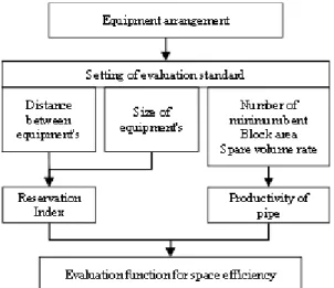
Layout design optimization of pipe system in ship engine room for space efficiency
8
0
0
전체 글
(2)
(3)
(4)
(5)
(6)
(7)
(8)
수치

관련 문서
The design method for the optimization of FRP leaf spring is proposed by applying design method of experiment in order to improve the characteristics of
In this paper, the variable capacitors and the superconducting relay antenna were applied to the superconducting WPT system to increase efficiency and the transmission distance
Edit the layout in the design magazine, the nature of the design, the designers are trying to convey the power of the message depends on the magazine
선박기본설계개론, 2006.3 Computer Aided Ship Design 2008 Computer Aided Ship Design 2008 –– PART III: Optimization Methods , 2006.3 PART III:
Appendix C. Solution of Systems of equation by optimization method.. 2009 Fall, Computer Aided Ship Design – Part1 Optimal Ship Design.. @ SDAL Advanced Ship
Design Theories of Ship and Offshore Plant, Fall 2016, Myung-Il Roh 1.. Design Theories of Ship and Offshore
Design Theories of Ship and Offshore Plant, Fall 2017, Myung-Il Roh 1.. Design Theories of Ship and Offshore
[6.1] Calculate the rule required minimum design still water bending moment and vertical wave bending moment of the design ship in accordance with the DNV Rule(Part 3,
