• 검색 결과가 없습니다.

Paddling Posture Correction System Using IMU Sensors

N/A
N/A
Protected

Academic year: 2021

Share "Paddling Posture Correction System Using IMU Sensors"

Copied!
7
0
0

로드 중.... (전체 텍스트 보기)

전체 글

(1)

http://dx.doi.org/10.5369/JSST.2018.27.2.86 pISSN 1225-5475/eISSN 2093-7563

Paddling Posture Correction System Using IMU Sensors

Kyungjin Kim and Chan Won Park

+

Abstract

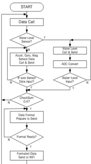
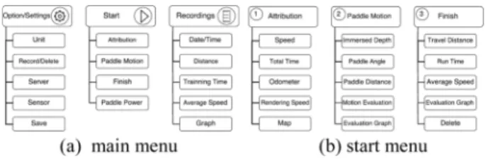
In recent times, motion capture technology using inertial measurement unit (IMU) sensors has been actively used in sports. In this study, we developed a canoe paddle, installed with an IMU and a water level sensor, as a system tool for training and calibration pur- poses in water sports. The hardware was fabricated to control an attitude heading reference system (AHRS) module, a water level sensor, a communication module, and a wireless charging circuit. We also developed an application program for the mobile device that pro- cesses paddling motion data from the paddling operation and also visualizes it. An AHRS module with acceleration, gyro, and geo- magnetic sensors each having three axes, and a resistive water level sensor that senses the immersion depth in the water of the paddle represented the paddle motion. The motion data transmitted from the paddle device is internally decoded and classified by the appli- cation program in the mobile device to perform visualization and to operate functions of the mobile training/correction system. To con- clude, we tried to provide mobile knowledge service through paddle sport data using this technique. The developed system works reasonably well to be used as a basic training and posture correction tool for paddle sports; the transmission delay time of the sensor system is measured within 90 ms, and it shows that there is no complication in its practical usage.

Keywords: IMU sensor, AHRS, Posture correction system, Paddle Sports, Mobile knowledge service.

1. INTRODUCTION

With the development of semiconductor manufacturing technology and microfabrication technology based on this, the technology and application fields of inertial measurement unit (IMU) sensors using microelectromechanical systems (MEMS) sensor elements are expanding widely [1-3]. Therefore, the scientific analysis of sports training using motion sensing technology has been attempted to acquire and analyze sensor signals by attaching specific sensors to various parts of sports equipment [4,5].

In recent years, high-speed IMU sensors have been developed and employed in robot and drone technologies. Remote control devices for three-dimensional (3D) games using these sensors have been popularized and the introduction of technologies for transmitting swing motion for baseball and golf suggests that the

era of sports science is fast approaching [6-9]. In addition, Microsoft's Kinect technology [10] and Leap motion technology [11], which have similar principles, are the leading technologies in the realization of motion capture.

Although various motion sensing techniques have been developed, in the case of paddling movement in water sports such as boats, canoes, and kayaks, the analysis method in the existing studio environment is difficult for use in the field on the real water surface. There is a lack of realism and a device with sensor is yet to be developed which can be placed directly on the water to detect motion in real time as well as the depth of in-water [12,13].

The paddling operation must be performed at the appropriate motion and timing with respect to the intake angle, the depth of entry of the paddle, and the watering operations to the surface of the paddle so that the hull can move effectively. However, only a certain degree of approximate measurement of the simple paddling operation is required to acquire the basic operation pattern reference without requiring high speed and accurate positional measurement such as motion detection of golf or baseball [7-9].

In this study, we have developed a device that can transmit the paddling operation of the user wirelessly by attaching a sensor, signal processing circuit, communication circuit, power circuit, etc. to the paddle. In addition, the obtained paddling motion state is compared with the motion patterns of existing athletes so that Dept. of Electrical and Electronics Engineering, Kangwon National University,

1 Kangwondaehak-gil, Chuncheon-si, Gangwon-do 24341, Korea

+

Corresponding author: [email protected]

(Received: Feb. 26, 2018, Revised: Mar. 26, 2018, Accepted: Mar. 26, 2018)

This is an Open Access article distributed under the terms of the Creative Commons Attribution Non-Commercial License(http://creativecommons.org/

licenses/bync/3.0) which permits unrestricted non-commercial use, distribution,

and reproduction in any medium, provided the original work is properly cited.

(2)

the similarities are indicated. With the aim of improving efficiency and practicality for better use in the field training system, we have developed a mobile application that uses this information to provide real-time analysis and feedback.

2. CONFIGURATION OF PADDLING MOTION DATA ACQUISITION SYSTEM

As shown in Fig. 1, the system developed in this study consists of devices recognizing paddling motion in water sports such as canoe, kayak, and leisure boat. The paddle itself is equipped with various sensors, as well as signal processing and transmission circuits to analyze motion data such as the user's paddling angle and paddling movement distance so that the user can achieve systematic training. For this purpose, the paddle is equipped with a 3D motion recognition sensor which obtains the motion data and displays it on the application. The system also comprises of an external server and a terminal that communicates with the external device.

2.1 Configuration and operation of paddle hardware

The hardware configuration of the paddle part of the system to be implemented is shown in Fig. 2. The power supply is made up of a charge power source (CPS) installed as a charging bay on the paddle stand. The CPS converts the power voltage from AC 220 V to DC 12 V and supplies it as AC current through a wireless power transmission coil. The circuit also includes a charge control unit (CCU) for controlling the wireless power supply and the voltage of a 3.0 V to 4.2 V ranged lithium polymer battery on the paddle.

The circuit is configured on the main board with a power supply controller that supplies stable voltage to the main processor unit

(MPU), sensors and communication module. There is also an AHRS module [14,15] equipped with an IMU (InvenSense Inc., MPU-9150A) and a Wi-Fi module for data transmission to a mobile device. The power source of the paddle is operated by a wireless charging method using an electromagnetic induction coil, so that the built-in lithium polymer battery can be charged. The power on/off of the built-in lithium polymer battery can be easily controlled by the mobile device. This eliminates the external switches and terminals of the paddle exposed to moisture and water, thereby improving the electric insulation protection and reliability.

The internal lithium-ion battery (18650) has a capacity of 3000 mAh, sufficient to drive the MPU board, sensor module, and the wireless transmission (Wi-Fi) module of the device all day long at an average power consumption of 150 mA. An over-discharge circuit was added so that the CCU is automatically powered off for voltages less than 3.0 V to protect the battery.

An 8051 based MEGAWIN's MPU (MG82FG5A64) transmits the information of the AHRS module and the water level sensor on the paddle to the Wi-Fi communication module.

A DC-DC converter is used to boost the battery’s voltage from 3.7 V to 5 V and the battery is then used as the power supply for the MPU and water level sensor. The battery voltage is then dropped to 3.3 V, and it supplies the power to the AHRS and Wi- Fi module.

The water level sensor converts the change in water level to a resistance value, which is then converted to a voltage change through the bridge circuit, and after amplification by an op-amp circuit, is sent to the analog input of the A/D converter of the MPU.

3D motion recognition of the paddling uses a small AHRS module equipped with a 9-axis MEMS type of IMU sensor integrated with three axes (x, y, z) of acceleration sensors, three gyros, and three geomagnetic sensors. The operating speed of each sensor is 1000 Hz, 1000 Hz, and 120 Hz, respectively. This IMU sensor is positioned at the center of the paddle as it is the best place for sensing the user's motion. Since the output of the Fig. 1. Schematics of the paddling motion data acquisition system

Fig. 2. Block diagram of the paddle hardware system.

(3)

IMU is sensitive to the direction of attachment, the IMU's acceleration along x-axis is correctly aligned so that it is perpendicular to the web side, which is the lower axis of the paddle. Fig. 3 shows photos of the preliminary and prototype paddle used in this work.

The American eTape liquid level sensor [16] is used to measure the water level when the paddle is immersed in water. The reference resistance of the sensor is 1500 Ω, the sensitivity is 56 Ω/ cm ±10%, and its resistance range is 300 Ω (fully in water) - 1500 Ω (out of water). Since this is a strain gauge type sensor the output signal is too small; hence, an amplification circuit for the output signal is added. The water level sensor should be positioned such that the sensor area is in contact with the water surface and the paddle is able to distinguish the water level change.

Repeated tests of the water level sensor showed that the sensor responds only to the depth direction of the water level and that the change in its resistance is not affected by the horizontal water pressure caused by the paddle operation. Fig. 4 shows the pictures of the main board and sensor modules of the paddle system.

2.2 Configuration and operation of the paddle software

Figure 5 shows a brief flowchart of the software for data transmission between the main board and sensor module. The AHRS module internally converts the data of the gyro sensor and acceleration sensor from the MPS915 IMU sensor to the roll, pitch, and yaw values of the paddle motion information and then transmits the final data to the MPU of the main board. The MPU carries out data call of the acceleration, gyro, and geomagnetic sensors of the AHRS module and water level sensor, and then transmits them to the Wi-Fi module. Because the output of the water level sensor is an analog signal, the data are converted into a digital value through the 16-bit A/D converter on the MPU chip before transmission. The MPU formats the input data according to the data protocol and transmits it wirelessly to the application program on the mobile device through the Wi-Fi communication module on the MPU board.

Fig. 3. Pictures of the fabricated paddle; (a) preliminary for test and (b) graphite fibered prototype.

Fig. 4. Main board and sensor modules of the paddle system.

Fig. 5. Flowchart of the main board control

(4)

2.3. Application program for the paddle visualization

Figure 6 shows the paddle visualization application program which is achieved through the data protocol and processing. This was done by designating the signaling protocol of the sensor used in the APP production, minimizing the delay rate, and improving the transmission rate. The basic allocation of memory per variable was 4 bytes; however, the data were compressed to 2 bytes for data transfer and data size was decreased through normalization, thus minimizing data loss.

To reduce the size of the data transmitted from the paddle, the received data packet was decoded. Because the decoded data consisted of different data, data classification was performed. In order to enhance the accuracy of the data, it was necessary to check whether there was a loss rate of the current data through the value of the check sum. If there was any loss of data, it was excluded from the analyzed data. These data together with the gyro sensor values were combined to form the paddle motion operation. The maximum /minimum value of the span and the average data change per second were calculated and used to determine the position and current operation of the paddle and to visualize the image. Table 1 shows the amount of span value for each sensor obtained by the average paddling operation.

Meanwhile, the transmission data from the paddle are unsuitable for providing user posture information to the application program because the data had undergone minimum computation on the paddle MPU. The user’s momentum, instantaneous travel distance, immersion depth of water level, and slope information of the paddle were used to develop the motion analysis algorithm. Through the extraction of the user’s motion information, the moving distance, instantaneous and average speeds, paddle depth from the water surface, and paddle angle to the water level were provided as information for visualization.

The method for expressing the momentum was performed as

follows. First, the depth of the paddle was reflected in the evaluation index by using the data obtained from the water level sensor. Next, the travel distance of the paddle was calculated by accumulating the difference between the current and previous values obtained by the acceleration sensor, while the slope of the paddle was determined by the pitch of the axis in the vertical direction when the paddle was vertical (absolute coordinate) among the input roll, yaw, and pitch, and then reflected in the evaluation according to the Euler angle of the pitch. Table 2 lists the evaluation table that divides the depth and angle of the paddling operation and the movement distance by one paddling operation into four levels and three levels, respectively.

Table 1. Span values of the water sensor, gyroscope and acceler- ometer

Sensor Max Min

W.Sensor 1340.2 0.0

Roll 1.4875 0.2

Pitch 0.915 -1.022

Yaw 0.878 1.4952

Acc. X 0.642 0.463

Acc. Y 0.634 -0.92

Acc. Z 0.933 -0.875

Fig. 6. Flowchart of the application program on the mobile device

(5)

3. RESULTS AND DISCUSSIONS

In order to test the communication between the paddle and the mobile device, the data transmission test was carried out through Wi-Fi communication. In order to check the accuracy of the data conversion, we created an application program, shown in Fig. 7, that provides the real-time display of each sensor. A change in the sensor output data due to the movement of the paddle was observed with the developed program, which was used for the span value, the initial value, and the calibration operation.

As a result of actual evaluation of the paddle for 10 hours a day, the problems caused by the gimbals lock phenomenon and the cumulative error of the gyro sensor, which frequently occur in general motion detection, became negligible after the initial calibration of the paddle.

The application program displays the transmitted data as a graph on the mobile monitor. Figure 7 shows the change in the gyro X, Y, Z axes, acceleration X, Y, Z axes, and water level sensor value. Figure 7(a) shows the paddle in an idle state, (b) indicates the changes in state when the gyro is changing in the x- axis direction with the changes of the acceleration in all three axes while (c) indicates the acceleration sensor moved in the x-axis direction and (d) shows the changes in the water sensor.

Figure 8 shows a tracking of the actual paddling motion on the water using the developed application program. The graph shows the paddle motion before and after the paddle was immersed and navigated in the water. This is a graph showing the paddle operation for 6 seconds on the graphical display of the motion change for each sensor (acceleration X, Y, Z, gyro roll, pitch, yaw, and water level sensors). One paddling reference is indicated based on the water level sensor entering and exiting the water once. The immersion depth of the paddle is indicated by the positive amount of increasing depth. Because the sensor output values and the display amounts are different from each other, normalization is performed to display the graphs.

Figure 9 shows a picture of the response speed test platform of

the paddle motion system produced in this study. A mechanical stimulus is applied to the AHRS module and the water level sensor to measure the time until the response is displayed on the Table 2. Evaluation tables of the paddle depth, angle, and travel dis-

tance in the water.

“bad” “shallow” “good” “deep”

Paddle depth below 25 cm 20 ‒35 cm 35-45 cm above 45 cm

“Bad” “Good” “Excellent”

Paddling Angle

below -20°

or above 20°

-20°~ -5°

or 5°~ 20° -5°~ 5°

Paddle travel

distance below 1.45 m 1.45 ‒1.75 m above 1.75 m

Fig. 7. Sensor test displays of the output value changes for each sen- sor’s axis

Fig. 8. Graphs of the paddle motions when the paddles; (a) enter to the water, (b) move in the water, (c) get out of the water, (d) move on the water.

Fig. 9. Experimental setup of the motion platform response time

(6)

mobile device. As shown in Fig. 10, the response time of the IMU sensor (gyro, acceleration, and geomagnetic) and the water level sensor were tested to be within 90 ms at the motion platform. This shows that it is reasonable to express the paddle motion from the data output of the sensors to the mobile platform.

Figure 11 shows the initial screen and each menu of the developed application program. The initial screen consists of options/settings, training start, and previous recordings. Under the start menu, operation information of the attributions, records of the paddle motion, training finish, and control of the paddle power can be selected.

When a user touches the start screen on the application, the current speed, cumulative time, odometer, rendering speed, and map are displayed in the attribution menu. In paddle motion menu, the depth of paddle’s immersion, the slope and travel distance of paddle, and evaluation and its graphs are displayed.

The previous record menu in the main menu allows a user to view previous records and display the date and time, travel distance, training time, average speed, and its evaluation graph. Through the evaluation record, the user can see at a glance whether the record has progressed.

Figure 12 shows the map display of the traveling information and the information about each evaluation of the paddle motion (the immersion depth of the paddle, the slope angle of the paddle, the moving distance of the paddle), and the graph for their evaluation at the bottom window.

At the end of the exercise, the movement distance, the running

time, the average speed, and the paddle motion graph are displayed, and the user's record can then be confirmed. Under the previous record menu, the date and time, evaluation graph, moving distance, training time, and the average speed are displayed.

Figure 13 shows the results obtained by three users performing on the field tests for the beginner, intermediate (leisure user), and expert (professional player) using the paddle and the application program. In the case of the professional player, the paddle speed, paddle depth, paddle slope, and the distance traveled by the paddle had been well received, for the leisure user it was observed that the distance and speed of the paddle slowed over time. On the other hand, the beginner had good speed and paddle movement distance at first, but the whole evaluation gradually got worse.

These results show that the product developed is suitable for training and education.

4. CONCLUSIONS

In this study, we have tried to provide a paddle motion training system. We developed hardware to receive paddling motion data from IMU sensor and water level sensor, and to place it on the paddle to transfer it to a mobile device. In addition, we developed Fig. 10. Response time vs. number of test curves for each sensor

Fig. 11. Pull down menu bars of the training application program and its sub menus.

Fig. 12. Mobile screen displays of the paddling exercise; (a) map and paddle motion evaluation, (b) previous records screen

Fig. 13. Field test results of the (a) professional player, (b) leisure

user, and (c) beginner

(7)

a mobile application program that performs data decoding, classification, and computation internally, thereby providing a paddling posture correction system using the new mobile knowledge service.

The device developed in this study is not as precise as the existing precise motion capture system because our work pursues precision to the extent of approximating the paddle motion posture. Experimental results show that cumulative errors and gimbals lock phenomena of sensors were not observed when the acceleration sensor and gyro sensor are periodically calibrated.

The purpose of this study is to provide a basic technology and more convenient method for the development of a simple motion detection system for paddle sports.

This device has the potential to be utilized as an application service for expressing the paddling angle, depth of entry, and paddle moving distance by using a mobile device and in correcting the posture of the user. In the future, it is expected to be used in various fields as an effective sports learning support system not only for canoes but also for other sports where a paddle is used and is especially not limited to space and place.

ACKNOWLEDGMENT

This study was supported by 2015 Research Grant from Kangwon National University (No. 520150454)

REFERENCES

[1] H. J. Luinge and P. H. Veltink, “Measuring orientation of human body segments using miniature gyroscopes and accelerometers”, Medical & Biological Engineering &

Computing, Vol. 43(2), pp. 273-282, 2005

[2] S. O. H. Madgwick, J. L. A. Harrison, and R. Vaidyanathan,

“Estimation of IMU and MARG orientation using a gra- dient descent algorithm”, 2011 IEEE International Con-

ference on Rehabilitation Robotics, pp. 1-7 Zurich, Switzerland, 2011

[3] X. Niu,1 Q. Wang, Y. Li, Q. Zhang, and P. Jiang, “An IMU evaluation method using a signal grafting scheme”, MDPI, Sensors (Basel). Vol. 16, pp. 854-875, 2016

[4] M. Kok, J. D. Hol, and T. B. Schon “Using inertial sensors for position and orientation estimation”, Foundations and Trends® in Signal Processing, Vol. 11(1-2), pp. 1-153, 2017 [5] H. Zhou, T. Stone, H. Hu, and N. Harris, “Use of multiple wearable inertial sensors in upper limb motion tracking”, Medical Engineering & Physics, Vol. 30(1), pp. 123-133, 2006

[6] S. H. Chu and C. Oh, "Development of safety evaluation index of bicycle using inertial sensor", Proc.of Journal of Korea Transportation Research Society, Vol. 64, pp. 780- 785, 2011

[7] N. Lee, M. Erickson, and P. Cherveny, “Measurement of the behavior of a golf club during the swing”, Thain, E., ed., Science and Golf IV: Proceedings of the World Scientific Congress of Golf, Routledge, London, UK, pp. 374-386, 2002.

[8] I. Wright, “Motion Capture in Golf", Annual Review of Golf Coaching, TaylorMade - adidas Golf, California USA, pp. 161-182, 2008

[9] https://www.drivelinebaseball.com/2011/06/our-motion- capture-lab-the-overview/(retrieved on Dec. 8, 2017).

[10] A. Jana, “Human skeleton tracking”, Kinect for Windows SDK Programming Guide, Packt Publishing, Birmingham, UK, ch.6., pp. 157-209, 2012

[11] B. Sanders, Mastering Leap Motion, Packt Publishing Ltd., Birmingham, UK, pp. 199-253, 2014

[12] https://www.wikihow.com/Paddle-a-Canoe/(retrieved on Jun. 13, 2017).

[13] https://www.kayakpaddling.net/#tutorials/(retrieved on July.

13, 2017).

[14] https://www.xsens.com/tags/ahrs//(retrieved on Jan. 12, 2018).

[15] http://x-io.co.uk/open-source-imu-and-ahrs-algorithms/

(open source), x-io Technologies/(retrieved on Jan. 13, 2018).

[16] Milone, “eTape continuous fluid level sensor operating

instructions and application notes”, Milone Technologies

Application Note, Milone Inc., New Jersey, USA, pp. 1-11,

2013.

수치

Fig. 2. Block diagram of the paddle hardware system.
Fig. 4. Main board and sensor modules of the paddle system.
Table 1. Span values of the water sensor, gyroscope and acceler- acceler-ometer
Fig. 8. Graphs of the paddle motions when the paddles; (a) enter to the water, (b) move in the water, (c) get out of the water, (d) move on the water.
+2

참조

관련 문서

In addition, using the properties of water shown in diverse shapes, Ki Hyung-do's recognition on the reality and future consciousness from regression of

Protecting the aquatic ecosystem in the water body Recover water and resources from wastewater and. produce renewable energy using wastewater constituents.. • So, the goal

In nuclear power plants, the water level is maintained by controlling the water supply when the steam generator's water level deviation occurs. During

The purpose of the study is to develop a sensor data collection and monitoring system with database using IoT techrology and to apply the ststem to three

(a) The initial slopes of the water-uptake curve of PSMA ion- omers neutralized with various cations and (b) ratios of the weight of the ionomer with maximum absorption of water

The inlet temperatures of each stages and return water, evaporation rates of each stages and total fresh water generating rates were predicted. By varying

The author, therefore, propose a fuzzy-PID controller which combines PID control and fuzzy technique to obtain the good performance of water level control

In this study, water flow system of Danghang Bay, which has the narrow and long topographical characteristics with the narrow bay mouth and its flow