INTRODUCTION
All ceramic inlay, onlay, veneers and crowns can provide some of the most esthetically pleasing restorations currently avail- able.1-3Similar to any other dental restoration they also have to respect health of surrounding living tissues.4According to De Van’s words in a simpler way, “Do no harm”should be the first objective of any clinician doing a restorative procedure.
When periodontal tissues are considered marginal fit along with contour and surface texture, are critical clinical parameters to determine success of the restoration.5The all ceramic restora- tions may get distorted during its complex manufacturing process and lead to marginal discrepancy.6 Quality of the marginal fit not only affects the biologic integrity5,7-10of both restoration and surrounding tissues but also affects the phys- ical, mechanical6,11and aesthetic properties of the restora- tion.
Alumina is used in industry as a reinforcing phase in high- clay low-feldspar porcelain used for fabricating electric insu- lators. Introduction of alumina reinforced porcelain in dentistry by McLean and Hughes was a significant step in the evolution of dental ceramics. In the late 1950s they developed a technique that involved the buildup of an inner core containing a high per- centage of crystalline alumina reinforcing phase. The alumi- na was embedded within a low-fusing, high-alumina content glassy matrix.12,13The strength of these new reinforced porce- lains were approximately double that of the conventional feldspathic materials.13
Slip cast technique (In-Ceram, VITA Zahnfabrik, Germany) has been a popular technique to prepare glass infiltrated alu- mina cores originally developed in 1983 by Dr. Sadoum of Biomaterial Research Laboratory at University of Paris.14 Recently Turkom-Cera fused alumina core system has intro- duced an alternative and innovative technique that can be called
A comparison of marginal fit of glass infiltrated alumina copings fabricated using two different techniques and the effect of firing cycles over them
Hirasankar Bhowmik1*, BDS, MDS, Rambhao Parkhedkar2, BDS, MDS
1Department of Prosthodontics, Sinhgad Dental College and Hospital, Pune,
2Saraswati-Dhanwantari Dental College and Hospital, Parbhani, India
PURPOSE. This study evaluated marginal fit of glass infiltrated alumina cores fabricated using two techniques and their marginal stability after firing cycles of veneering porcelain. MATERIALS AND METHODS. Fifteen standardized all-ceramic crowns were fabricated on a metal die using each technique: slip cast technique of VITA In-Ceram sprint Alumina (Group A as control) and plastic foil matrix technique of Turkom- Cera fused alumina core system (Group B). Copings were compared between groups and within groups at coping stage and after firing each layer of veneering porcelain. A device was used to standardize seating of copings on the metal die and positioning of the specimens under the microscope after each stage of fabrication. The specimens were not cemented and marginal gap was measured using an image analyzing soft- ware (Imagepro Express) on the photographs captured under an optical microscope. Two tailed unpaired ‘t test’was used to compare mar- ginal gaps in two groups and one way ANOVA was used to analyze marginal distortion within each group at 95% confidence interval. RESULTS.
The marginal gap was smaller at the coping stage in group B (60 + 30 μm) than group A (81 + 21 μm) with statistical significance. After firing of veneering porcelain the difference was insignificant. At the final stage, both groups exhibited lower mean marginal gaps than at the initial coping stage with the difference of 11.75 μm for group A and 11.94 μm for group B, but it was statistically insignificant due to high value of stan- dard deviation. CONCLUSION. Within the limitations of this study, it was concluded that both techniques produced copings with comparable and acceptable marginal fit and marginal stability on firing veneering porcelain. [J Adv Prosthodont 2011;3:196-203]
KEY WORDS: Marginal gap; Firing cycle; Plastic foil matrix technique; All ceramic; Image analyzer
Corresponding author: Hirasankar Bhowmik
Department of Prosthodontics, Sinhgad Dental College and Hospital Pune 411041, India
Tel. 91 9860253240: e-mail, [email protected]
Received June 13, 2011 / Last Revison August 7, 2011 / Accepted November 25, 2011
ⓒ 2011 The Korean Academy of Prosthodontics
This is an Open Access article distributed under the terms of the Creative Commons Attribution Non-Commercial License (http://creativecommons.org/licenses/by- nc/3.0) which permits unrestricted non-commercial use, distribution, and reproduction in any medium, provided the original work is properly cited.
plastic foil matrix technique to prepare cores with similar struc- ture. It has an innovative modification of platinum foil tech- nique to produce all ceramic crowns. In this technique a plastic foil is adapted over the master die over which the slip (alumina gel) is applied. After the slip dries, it is removed from the die with the supporting plastic foil and placed for sin- tering. In slip cast technique the master die has to be duplicated in a special plaster on which the slip is applied and sintered.
In both the techniques the porous frameworks are produced after sintering. Then porous frameworks are infiltrated with glass in a second firing process. Both techniques have stages of poten- tial discrepancy effecting marginal fit. Slip cast technique involves duplication of the master die which may incorporate errors in marginal fit. No such duplication is done in plastic foil matrix technique but the plastic foil which comes even over the prepared tooth margin on the die, may incorporate errors in mar- ginal fit.
A variety of methods has been used to evaluate the marginal fit of dental restorations such as direct viewing, cross section view, impression replica technique, clinical examination.5,15Direct viewing is a nondestructive and convenient method and has been most frequently used to measure marginal gap at various stages of manufacturing process. Various means of measuring marginal gap by direct viewing include Stereomicroscope,14-17 optical microscope,18-20optical microscope with image analyzing software,21-23Laser microscope,24Scanning Electron Microscope25-27 etc. There are various other non-destructive methods report- ed in the literature like profile projector28and laser videography.29 In this research direct viewing under an optical microscope has been used that allows examination of the same sample at various stages. An image analyzing software improved the quan- tity and quality of the data obtained.
Several researchers have tried to determine the range of clin- ically acceptable marginal gap which is not visible to the naked eye and clinically undetectable with a sharp explorer.
Christensen et al. evaluated the fit of supragingival and sub- gingival margins of gold inlays with group of dentists and stat- ed that the least acceptable marginal gap in visually accessi- ble surface was 39 μm, according to linear regression prediction formula.19He also reported that the range of clinically accept- able marginal gap was 34 to119 μm for subgingival and 2 to 51 μm for supragingival margins. Lofstrom and Barakat used scanning electron microscope to measure the supragingival mar- gins of the crowns that were considered clinically well fitting by several dentists and reported marginal gap value of 7 to 65 μm.25McLean and von Fraunhofer investigated the cement film thickness by an in vivo technique and stated that marginal gap of 120 μm should be the limit of clinical acceptability.30
The marginal gap of all ceramic restorations has been stud- ied in various researches and the average value ranges from 19 μm to 161 μm.14-16,18,22-24,31-47The results indicate great variations of marginal gap within a crown system and even within each
sample. Because of high variation of the values within same crown system, the mean value of all measurement locations can show a large local discrepancy and result in an increase in Standard Deviation (SD).28,41Although the SD in such studies has been reported to be approximately 20 μm.10,14,16,17,20,33-37In- Ceram crowns shows mean marginal gap of 27.5 μm14in one study and 123 μm44in another. According to Sulaiman, In- Ceram cores show marginal gap of 161 (46) μm.17Marginal sta- bility investigated by several authors showed no significant change in marginal gap on porcelain application over the conventional In-Ceram copings.14,17However, to the author’s knowledge no data is available in the literature for the new Turkom-Cera plastic foil matrix technique regarding mar- ginal fit.
In this study the comparison between two techniques of fab- ricating Glass infiltrated alumina cores and strength of the core was not considered. Therefore, Vita In-Ceram sprint Alumina was used instead of conventional In-Ceram to reduce the laboratory working time from 14 hours to 4 hours. Turkom- Cera with less than three hours of laboratory working time is practically comparable to Vita In-Ceram sprint Alumina.
This study was aimed to evaluate the marginal fit of glass infil- trated alumina copings prepared by two different techniques and also evaluate the effect of firing three layers of veneering porcelain over the copings.
MATERIALS AND METHODS
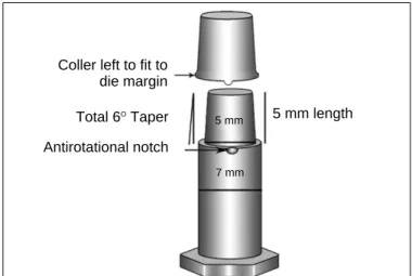
A metallic die (Fig. 1) was fabricated to simulate a prepared maxillary first premolar considering the average dimensions of the tooth according to Wheeler.48The die had a flat end con- ical shape and 1 mm shoulder all around with rounded axiogingival line angle. Taper of the preparation was 6�
according to the requirements of ideal crown preparation49and as recommended by the manufacturers. The shape of die
Fig. 1. Schematic diagram of metallic die and coping configurations.
Coller left to fit to die margin
Total 6OTaper Antirotational notch
5 mm length
5 mm
7 mm
helped in standardizing the coping thickness and also easy stan- dardization of veneering porcelain layer thickness. An anti-rota- tional notch was prepared on the margin to reproduce seating of the copings in same position at each stage of crown fabrication.
Fifteen specimens were prepared for each group. Group A consisted of cores prepared with Slip Cast technique of VITA In-Ceram sprint Alumina system (VITA Zahnfabrik H. Rauter GmbH & Co. Bad Sa¨ckingen. Germany) with aluminous veneering porcelain VITA VM7 (VITA Zahnfabrik, Bad Sa¨ckin- gen, Germany). Group B consisted of the cores fabricated with Plastic Foil Matrix technique of Turkom-Cera Fused Alumina Core System (Turkom-Cera SDN. BHD. Malaysia) with same aluminous veneering porcelain as group A.
Slip cast techniques is well known and documented in var- ious literatures.14-17,23,28,32,33,38The plastic foil matrix technique involves a 0.1 mm plastic spacer foil to be adapted on the die.
The spacer foil is supported by a 0.6 mm plastic foil and heat- ed over the flame till both starts sagging together. Then the die is dipped into a jar of silicon putty through the softened foils. The putty adapts the foil onto the die due to its viscos- ity. The supporting foil is removed and the spacer foil is cut till 1 mm below the die margin. Adaptation of spacer foil is refined using the edges of the supporting foil at the axiogin- gival line angle or any other line and point angles on the prepa- ration. The slip (alumina gel) is then applied onto the die. After the slip is dry, it is remover with the spacer foil and placed for sintering. During sintering the spacer foil burns out and a porous framework is obtained. The remaining procedures are similar in both the techniques. The frameworks are finished to desired thickness and contour. Then the frameworks are examined for structural integrity with a checking liquid to rule out cracks devel- oped during finishing. The frameworks with cracks are discarded and the intact frameworks are subjected to glass infiltration pro- cedure. After glass infiltration no adjustments are possible in
the copings except removal of excess glass. To simulate the fab- rication procedure of a crown, veneering porcelain was built up over each core in three layers which are base dentine, dentine and enamel.
Measurement of marginal gap of all the samples were recorded at four stages e.g. coping (stage I), after base dentine layer firing (stage II), after dentine layer firing (stage III) and after enamel layer firing (stage IV). Copings were prepared as per respective manufacturers’instructions. The copings were approximately 0.5 mm in thickness and at the margin 0.3 to 0.5 mm thick collar was left to conform to the 1 mm shoulder of the die. Porcelain layers were standardized with three counter dies (Fig. 2) that helped building each layer to predeter- mined dimensions. No porcelain was added on the collar of shoul- der margin left in the copings. All the laboratory procedures were done by a single person to avoid interpersonal variations.
Felton et al. discussed different terminologies used to define
“The Fit”of a restoration.4In this study the linear distance between the lowest outer margin of the coping and the cavo- surface line angle of die margin along the long axis of the die was defined as the absolute marginal gap.50As the die margin was perpendicular to its long axis, the marginal gap was measured perpendicular to the die margin.
An optical microscope (Olympus BX 51) with image analyzing software (Image-Pro Express version 6.0.0.318, Media Cybernetics Inc.) was used for measurement on the digital pho- tographs captured at 100 × magnification. An external light source directed light obliquely onto the marginal area of samples to illuminate only the outer surfaces of both copings and the die. The die was oriented transversely on the platform under the microscope keeping the die surface perpendicular to the direction of view. A custom made magnetic die orientation device (Fig. 3) was prepared to standardize orientation of the die under the microscope.
Fig. 2. Schematic diagram of metallic counter dies for porcelain buildup; A: base dentine, B: dentine and C: enamel.
A
B
C
Fig. 3. Magnetic die orientation device and its placement under the micro- scope.
In every stage, six average values were recorded for each spec- imen at six fixed zones. The markings near the die margin helped reorientation of specific zones of the copings under the microscope. Thus, same areas of a coping were measured at all four stages. The copings with overextended margins at any of the focusing zones were not included in the study.
Photographs of the marginal areas were captured at each zone at standardized orientation and placement of the samples.
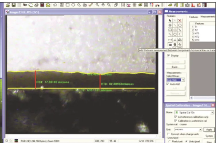
In all photographs margin was traced with the help of image analyzing software (Fig. 4). The coping margin which is mostly irregular was traced either manually or automatically by the software depending on the clarity and contrast of the cop- ing margin on the photograph. Keeping the die margin at the horizontal line the average vertical distance between the trace line at die margin and the irregular trace line of coping margin was calculated by the software. Each focusing zone had a width of approximately 645 μm (= 702 pixels) at 300 dpi res- olution and 100 × magnification. Therefore in one focusing zone, computed average marginal gap measurements can be explained as the average of 702 point measurements at each pixel level. Thus average of total 4212 (702 × 6) point mea- surements spread over 3.87 mm of margin (645 μm × 6) dis- tributed at 6 zones represented overall marginal gap of each sam- ple at each stage. Thus 30 samples at 4 stages generated total 720 average values from an equivalent of total 505440 point measurements.
Rotation of the samples while viewing under the microscope on the horizontal plane was corrected by rotating the captured photograph using the image analyzing software (Fig. 5). The software also allows superimposition of two photographs taken at two different levels of focus. Therefore, even if the mar- gin of the coping and the cavosurface line angle of the die are at varying depth, two different photographs in the same spa- tial position of the specimen under the microscope were cap- tured at different focusing level. Then superimposing the photographs both the die margin and crown margin were traced accurately (Fig. 6) and vertical distance between them was measured.
To determine the significance of difference between two groups, two-tailed unpaired ‘t’test was performed at each stage of crown fabrication. The magnitude of marginal distortion within the groups on porcelain firing was done with one way ANOVA test to know whether there was any significant change in marginal gap on porcelain firing. If significant results were obtained, the Tukey’s post hoc analysis was planned for multiple comparisons to pin point the stage of crown fabrication where significant changes in marginal gap had occurred.
RESULTS
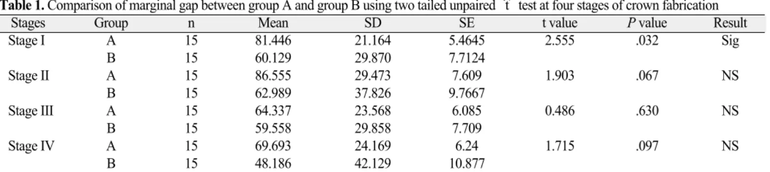
Two-tailed unpaired ‘t’test in Table 1 shows significant dif- ference in mean marginal gap between groups at coping
Fig. 4. Tracing of die and coping margins with image analyzing software.
Fig. 5. Correction of rotated image with the image analyzer.
Fig. 6. Photographs captured at different focus level of same marginal area for superimposition.
stage (P<.05) where Turkom-Cera plastic foil matrix technique showed lower values of marginal gap than slip cast tech- nique. The difference in mean values was maintained even after three layers of porcelain firing, but it was not statistically sig- nificant.
The results of ANOVA test in Table 2 shows insignificant dif- ference within the group on firing 3 layers of veneering porcelain. As the changes within group were found to be statistically insignificant, post hoc multiple comparison test was not carried out.
At coping stage mean marginal gap values (SD) were 81 (21) μm in group A and 60 (30) μm in Group B (Fig. 7). The obser- vations in group A ranged between 0 to 186 μm and in group B it was between 0 to 216 μm at coping stage. Such great vari- ation within samples and groups was maintained in all four stages and had significant influence on the statistical analysis. The stan- dard deviations in both groups were large proving the fact that there were both well fitting and poorly fitting zones within the groups and also within the same sample.
In both groups, mean marginal gap is increased on first layer firing. Finally at stage IV in both groups, marginal gap was reduced and was lesser than the initial values at coping stage.
Even though there were obvious changes occurring in mean marginal gap values with porcelain firing, the changes were sta- tistically insignificant due to large values of standard deviation.
The differences of mean marginal gap between stage I and stage IV were 11.75 μm for group A and 11.94 μm for group B.
DISCUSSION
In this study, cementation of the coping during measurement was avoided to eliminate the variability in cementation procedure for each coping in terms of viscosity of mix and force applied.
Further it would have severely complicated evaluation of marginal stability on three consecutive firing of veneering porce- lain. Measuring marginal opening of sectioned specimens under a microscope can be misleading. It gives impression that Table 1. Comparison of marginal gap between group A and group B using two tailed unpaired ‘t’test at four stages of crown fabrication
Stages Group n Mean SD SE t value P value Result
Stage I A 15 81.446 21.164 5.4645 2.555 .032 Sig
B 15 60.129 29.870 7.7124
Stage II A 15 86.555 29.473 7.609 1.903 .067 NS
B 15 62.989 37.826 9.7667
Stage III A 15 64.337 23.568 6.085 0.486 .630 NS
B 15 59.558 29.858 7.709
Stage IV A 15 69.693 24.169 6.24 1.715 .097 NS
B 15 48.186 42.129 10.877
SD = Standard Deviation, SE = Standard error, n = number of sample, NS = Not significant, Sig = Significant.
Table 2. Statistical analysis of marginal gap in four stages of crown fabrication using one way ANOVA for group A and group B
Groups Source SS df MS F P value Result
Group A Between groups 4738.674 3 1579.558 2.572 .0631 NS
Within groups 34387 56 614.0535
Total 39125.67 59
Group B Between groups 1917.514 3 639.1712 0.5124 .6753 NS
Within groups 69852.67 56 1247.369
Total 71770.18 59
SS = Sum of squares, df = Degree of freedom, MS = Mean square, F = f ratio, NS = Not significant.
Fig. 7. Mean marginal gap in group A and B in four stages of fabrication.
100 80 60 40 20 0
Group A Group B
A B A B A B A B Stage I Stage I I Stage III Stage I V
the marginal openings are the same along the entire circum- ference of the crown as stated by Chan et al.31 Further it destroys the samples and cannot be used for investigation of marginal stability on porcelain veneering.
Measurement with an optical microscope has the disad- vantage of limited depth of view field.28 Unless the two points to be measured are on the same plane, it is not possible to focus on both points at a time. In this study, this problem was solved with the Image analyzing software which allows superimposition of two photographs of the same zone captured at two different levels of focus (Fig. 6).
Groten et al.51determined minimum number of marginal gap measurements required for in-vitro testing. According to his data, 50 measurements per crown are suggested, but at least 20 to 25 measurements per crown are required according to the aimed precision level. Measuring crown margins at 4 to 12 sites per crown might be misleading; particularly when the fit of dif- ferent crown systems or manufacturing stages are compared.
This potential lack of relevant and consistent information should be compensated by large number of samples per group. However, in many studies 5 - 10 specimens were examined in each group.14,15,17,28,29,33,35,37 In all these studies points measurements were recorded to evaluate marginal gap ranging from 4 to 100 sites. To make adequate number of measurements in this study average width of the marginal gap in the whole focusing zone of 645 μm was measured at 6 dif- ferent sites of each coping rather than taking measurements at limited number of points. Total average gap at 3.87 mm of mar- gin (645 μm × 6) consisting of an equivalent of 4212 point mea- surements distributed at 6 zones represented overall mar- ginal gap of each sample. Moreover to fulfill the requirement of adequate data, 15 samples in each group were evaluated.
Measurements recorded at the same zones at all four stages increased relevance of the comparisons.
Previous studies indicated large variations of marginal gap within single crown system. The marginal gap of 87 (21) μm for Vita InCeram sprint alumina copings is in accordance with the range of values observed in previous studies with con- ventional In-Ceram. However, Pera et al. (27.5 μm),14Rinke et al. (34 μm),33Shearer et al. (22 μm)38and Balkaya et al. (57 μm)28found lower values whereas Yeo et al. (112 μm)23and Sulaiman et al. (161 μm)17reported higher values of mean mar- ginal gap for conventional In-Ceram core system. There are no previous studies available in the literature regarding mar- ginal fit of copings fabricated by Turkom-Cera plastic foil matrix technique. The mean marginal gap of 60 (30) μm for Turkom- Cera falls within the range of reported marginal gap of vari- ous all ceramic systems already existing.
Because of high variation of the values within same crown system, the mean value of all measurement locations shows a large local variation and results in an increase in SD. The mean values of the present study were accompanied by large SDs in
the range of 21 to 42 μm. There is a wide range of SD values reported in few previous researches done with conventional In- Ceram14-17,23,28,32,33,38and it was as high as 55 μm in the study con- ducted by Yeo et al.23
Firing shrinkage of veneering porcelain may cause dimen- sional changes in the underlying coping and influence marginal stability.17,21,26The present study shows statistically insignifi- cant change in marginal gap on application of veneering porcelain which is in agreement with several previous studies conducted by several authors like, Pera et al.,14Sulaiman et al.17 and Yeo et al.23There is reduction of mean marginal gap which is in contrast with the studies by Balkaya et al.28and Sulaiman et al.17Balkaya et al.28reported significant change in marginal fit in conventional InCeram crowns and also reported that there is a tendency of labiolingual diameter of the crown to decrease with concomitant increase in the mesiodis- tal diameter. Sulaiman et al.17found significant increase in mar- ginal gap at the lingual region of the anatomic test specimens.
He also showed positive correlation between the magnitude of marginal distortion and bulk of porcelain over the coping.
Similarly, Balkaya et al.28attributed the difference in marginal distortion at various regions of a crown to variable application of porcelain mass. In this study, the geometric shape of the die allowed to standardize thickness of porcelain layers in all direc- tions. Coping configuration also differs from the anatomical situation of a maxillary central incisor used as master dies in previous studies of Sulaiman et al.17and Balkaya et al.28The configuration of the copings and the pattern of porcelain application in this study can be closely compared to the mesial and distal area of the maxillary central incisor and thus can be co-related with the increase in the horizontal diameter of the copings reported by Balkaya et al.,28causing better seat- ing of the copings and improved average marginal fit.
The differences between the results of present study and the results of other studies are possibly due to various factors like, die configuration and material, method of measurement, location and number of measurements and measurement of cemented or noncemented crowns.
Dental literature reports that, although a marginal opening equal to that of 25 to 35 μm grain size (ADA specification No.
8) is acceptable, measurements in the clinical situation consistently exceed the defined value. Christensen19 reported that the range of clinically acceptable marginal gap was 34 - 119 μm for subgingival and 2 - 51 μm for supragingival margins, whereas McLean and von Fraunhofer30concluded that 120 μm was the maximum acceptable marginal opening. Lofsrom and Barakat25 reported clinically acceptable marginal gap values of 7 - 65 μm. Considering all these studies, the mean mar- ginal openings for both groups in this study were within the range of clinical acceptability with mean marginal gap of 70 (24) μm for Vita In-Ceram sprint system and 48 (42) μm for Turkom- Cera after porcelain application.
There are several limitations in this study. Studies may be conducted with anatomic dies, measurements of margin- al gap recorded after cementation, fixed partial denture situation, artificial aging etc. which will increase the clinical rele- vance. Slip cast technique has been investigated by several researchers.14-17,23,28,32,33,38Further investigations are necessary over- coming the limitations in this study to achieve more information about plastic foil matrix technique.
CONCLUSION
Within the limitations of this study, the following conclusions can be drawn:
1. Plastic foil matrix technique produced copings with bet- ter marginal fit (at coping stage) as compared to slip cast technique.
2. After firing three layers of veneering porcelain, copings of both group showed comparable marginal fit.
3. Both techniques produced crowns that showed marginal gap within the clinically acceptable limits reported by pre- vious researchers.
4. There was no significant marginal distortion in both sys- tems on firing veneering porcelain over the copings.
REFERENCES
1. Giordano RA. Dental ceramic restorative systems. Compend Contin Educ Dent 1996;17:779-82, 784-6 passim; quiz 794.
2. Raigrodski AJ. Contemporary materials and technologies for all- ceramic fixed partial dentures: a review of the literature. J Prosthet Dent 2004;92:557-62.
3. Conrad HJ, Seong WJ, Pesun IJ. Current ceramic materials and systems with clinical recommendations: a systematic review. J Prosthet Dent 2007;98:389-404.
4. Felton DA, Kanoy BE, Bayne SC, Wirthman GP. Effect of in vi- vo crown margin discrepancies on periodontal health. J Prosthet Dent 1991;65:357-64.
5. Sorensen JA. A rationale for comparison of plaque-retaining prop- erties of crown systems. J Prosthet Dent 1989;62:264-9.
6. Alkumru H, Hullah WR, Marquis PM, Wilson HJ. Factors af- fecting the fit of porcelain jacket crowns. Br Dent J 1988;164:39- 43.
7. Waerhaug J. Histologic considerations which govern where the margins of restorations should be located in relation to gingiva. Dent Clin North Am 1960;4:161-76.
8. Lo¨e H. Reactions to marginal periodontal tissues to restorative procedures. Int Dent J 1968;18:759-78.
9. Orstavik D, Orstavik J. In vitro attachment of Streptococcus san- guis to dental crown and bridge cements. J Oral Rehabil 1976;
3:139-44.
10. Faucher RR, Nicholls JI. Distortion related to margin design in porcelain-fused-to-metal restorations. J Prosthet Dent 1980;43:149- 55.
11. Tuntiprawon M, Wilson PR. The effect of cement thickness on the fracture strength of all-ceramic crowns. Aust Dent J 1995;
40:17-21.
12. McLean JW, Hughes TH. The reinforcement of dental porcelain with ceramic oxides. Br Dent J 1965;119:251-67.
13. Jones DW. Development of dental ceramics. An historical perspective. Dent Clin North Am 1985;29:621-44.
14. Pera P, Gilodi S, Bassi F, Carossa S. In vitro marginal adapta- tion of alumina porcelain ceramic crowns. J Prosthet Dent 1994;72:585-90.
15. Sorensen JA. A standardized method for determination of crown margin fidelity. J Prosthet Dent 1990;64:18-24.
16. Lui JL. The effect of firing shrinkage on the marginal fit of porce- lain jacket crowns. Br Dent J 1980;149:43-5.
17. Sulaiman F, Chai J, Jameson LM, Wozniak WT. A comparison of the marginal fit of In-Ceram, IPS Empress, and Procera crowns. Int J Prosthodont 1997;10:478-84.
18. Strating H, Pameijer CH, Gildenhuys RR. Evaluation of the mar- ginal integrity of ceramometal restorations. Part I. J Prosthet Dent 1981;46:59-65.
19. Christensen GJ. Marginal fit of gold inlay castings. J Prosthet Dent 1966;16:297-305.
20. Shillingburg HT Jr, Hobo S, Fisher DW. Preparation design and margin distortion in porcelain-fused-to-metal restorations. J Prosthet Dent 1973;29:276-84.
21. Buchanan WT, Svare CW, Turner KA. The effect of repeated firings and strength on marginal distortion in two ceramomet- al systems. J Prosthet Dent 1981;45:502-6.
22. Denissen H, Dozic′A, van der Zel J, van Waas M. Marginal fit and short-term clinical performance of porcelain-veneered CI- CERO, CEREC, and Procera onlays. J Prosthet Dent 2000;84:
506-13.
23. Yeo IS, Yang JH, Lee JB. In vitro marginal fit of three all-ce- ramic crown systems. J Prosthet Dent 2003;90:459-64.
24. Att W, Komine F, Gerds T, Strub JR. Marginal adaptation of three different zirconium dioxide three-unit fixed dental prostheses.
J Prosthet Dent 2009;101:239-47.
25. Lofstrom LH, Barakat MM. Scanning electron microscopic evaluation of clinically cemented cast gold restorations. J Prosthet Dent 1989;61:664-9.
26. Hamaguchi H, Cacciatore A, Tueller VM. Marginal distor- tion of the porcelain- bonded-to-metal complete crown: an SEM study. J Prosthet Dent 1982;47:146-53.
27. Gemalmaz D, Alkumru HN. Marginal fit changes during porce- lain firing cycles. J Prosthet Dent 1995;73:49-54.
28. Balkaya MC, Cinar A, Pamuk S. Influence of firing cycles on the margin distortion of 3 all-ceramic crown systems. J Prosthet Dent 2005;93:346-55.
29. May KB, Russell MM, Razzoog ME, Lang BR. Precision of fit:
the Procera AllCeram crown. J Prosthet Dent 1998;80:394-404.
30. McLean JW, von Fraunhofer JA. The estimation of cement film thickness by an in vivo technique. Br Dent J 1971;131:107-11.
31. Chan C, Haraszthy G, Geis-Gerstorfer J, Weber H, Huettemann H. Scanning electron microscopic studies of the marginal fit of three esthetic crowns. Quintessence Int 1989;20:189-93.
32. Vahidi F, Egloff ET, Panno FV. Evaluation of marginal adap- tation of all-ceramic crowns and metal ceramic crowns. J Prosthet Dent 1991;66:426-31.
33. Rinke S, Hu¨ls A, Jahn L. Marginal accuracy and fracture strength of conventional and copy-milled all-ceramic crowns.
Int J Prosthodont 1995;8:303-10.
34. Hung SH, Hung KS, Eick JD, Chappell RP. Marginal fit of porce- lain-fused-to-metal and two types of ceramic crown. J Prosthet Dent 1990;63:26-31.
35. Davis DR. Comparison of fit of two types of all-ceramic crowns. J Prosthet Dent 1988;59:12-6.
36. Weaver JD, Johnson GH, Bales DJ. Marginal adaptation of castable ceramic crowns. J Prosthet Dent 1991;66:747-53.
37. Holmes JR, Sulik WD, Holland GA, Bayne SC. Marginal fit of castable ceramic crowns. J Prosthet Dent 1992;67:594-9.
38. Shearer B, Gough MB, Setchell DJ. Influence of marginal configuration and porcelain addition on the fit of In-Ceram crowns. Biomaterials 1996;17:1891-5.
39. Boening KW, Wolf BH, Schmidt AE, Ka¨stner K, Walter MH.
Clinical fit of Procera AllCeram crowns. J Prosthet Dent 2000;
84:419-24.
40. Beschnidt SM, Strub JR. Evaluation of the marginal accuracy of different all-ceramic crown systems after simulation in the ar- tificial mouth. J Oral Rehabil 1999;26:582-93.
41. Chan C, Haraszthy G, Geis-Gerstofer J, Weber H. The marginal fit of Cerestore all ceramic crowns - A Primary report.
Quintessence Int 1985;6:399-402.
42. Komine F, Gerds T, Witkowski S, Strub JR. Influence of framework configuration on the marginal adaptation of zirco- nium dioxide ceramic anterior four-unit frameworks. Acta Odontol Scand 2005;63:361-6.
43. Stappert CF, Dai M, Chitmongkolsuk S, Gerds T, Strub JR.
Marginal adaptation of three-unit fixed partial dentures constructed from pressed ceramic systems. Br Dent J 2004;196:766-70; dis- cussion 760, quiz 780.
44. Grey NJ, Piddock V, Wilson MA. In vitro comparison of con- ventional crowns and a new all-ceramic system. J Dent 1993;21:47-51.
45. Wolfart S, Wegner SM, Al-Halabi A, Kern M. Clinical evalu- ation of marginal fit of a new experimental all-ceramic system
before and after cementation. Int J Prosthodont 2003;16:587-92.
46. Reich S, Wichmann M, Nkenke E, Proeschel P. Clinical fit of all-ceramic three-unit fixed partial dentures, generated with three different CAD/CAM systems. Eur J Oral Sci 2005;113:
174-9.
47. Stappert CF, Dai M, Chitmongkolsuk S, Gerds T, Strub JR.
Marginal adaptation of three-unit fixed partial dentures constructed from pressed ceramic systems. Br Dent J 2004;196:766-70; dis- cussion 760, quiz 780.
48. Ash MM, Nelson SJ. The Permanent Maxillary Premolars. In:
Wheeler’s Dental Anatomy, Physiology, and occlusion. 8th Ed. St. Louis, Sounder’s (Imprint of Elsevier Pub.), 2003. p. 243.
49. Rosenstiel SF, Land MF, Fujimoto J. Contemporary Fixed Prosthodontics. 3rd Ed. St. Louis, Mosby (reprint), New Delhi Harcourt Private Limited; 2002. p. 643-72.
50. Holmes JR, Bayne SC, Holland GA, Sulik WD. Considerations in measurement of marginal fit. J Prosthet Dent 1989;62:405-8.
51. Groten M, Axmann D, Pro¨bster L, Weber H. Determination of the minimum number of marginal gap measurements required for practical in-vitro testing. J Prosthet Dent 2000;83:40-9.