Implementation of SoC for NMEA2000 Ship Standard Network Protocol Using FPGA
Dong-Hyun Park1․Ji-Tae Hong2․Kyung-Yup Kim3․Yung-Ho Yu†
(Received November 25, 2009; Revised January 8, 2010; Accepted January 25, 2010)
Abstract:IEC61162-3 known as NMEA2000 protocol is approved as a standard network of SOLAS ship by ISO and used for the instrument network which exchanges data in real-time. For easy the development of ship network equipments, this study is focused on the development of SoC which can convert to NMEA2000 protocol from various kind of protocols such as TCP/IP, NMEA0183, RS422 and others using FPGA and u-Blaze. In this paper, we composed NMEA2000 protocol stack on FPGA and verified NMEA2000 network communication of FPGA system by connecting with commercialized devices through PC Hyper-terminal and network monitoring program.
Key words:NMEA2000, Ship Network, u-Blaze, FPGA, SoC
†Correspording Author(Korea Maritime Univ. Control & Instrumentation Engineering, E-mail:yungyu@
hhu.ac.kr, Tel : 051-410-4345)
1 Korea Maritime Univ. Control & Instrumentation Engineering.
2 Pusan National Univ. Electrical Engineering 3 Dong-A Univ. Engineering
1. Introduction
In Korea, the market of ship building has been grown as the world economy progresses. However, our ship material industry has not been significantly increased, it mostly depends on import.
IMO(International Maritime Organization) decided to take e-navigation for ship security and safety. E-navigation needs new integrated ship material system, but our ship material industry is not even ready to apply e-navigation. In this situation, if e-navigation start in 2012[1-2], Korea will not be available to keep prior occupation of world ship market. Therefore, it is important to secure the core technology of ship electronics and IT convergence material.
Realization of e-navigation is embodied by two stages. One is standardization and integration of existing technologies, the other is the implementation and the development of new technologies. Especially, in case of ship network, many kinds of network are used in the ship. Because of using various ship networks, it is possible to occur compatible problems among devices or obstruction of safety voyage.
Consequently, the adaption standard of ship network is necessary to integrate present networks. This standard of ship network is largely divided into two parts.
Firstly, NMEA(National Marine Electronic Association)2000 protocol known as IEC (International Electro-technology Commission) 61162-3 is used in instrument network
which exchanges data in real-time[1,3].
The other, MiTS(Maritime information Technology Standards) defined as IEC 61162-4 is used in control network.
NMEA2000 protocol and MiTS are already approved in ISO(International Organization for Standardization)[4].
Purpose of this research is the implementation of NMEA2000 protocol using FPGA, also, it is helpful to easily develope ship IT equipments connected to NMEA2000 network by supply SoC. This paper focuses on the verification of NMEA2000 protocol stack using FPGA and u- Blaze, and the composition of system for test of communication and compatibility between standard networks.
2. Protocol architecture
2.1 NMEA2000 protocol
Since 1994, NMEA2000 has been performed by leading of the NMEA committee which co-worked with the United States Coast Guard, universities, many navigation & communication equipment manufacturers and CAN solution companies.
The first specification of NMEA2000 was completed in 2001[5]. NMEA2000 is real-time communication network of SOLAS(international convention for the Safety Of Life At Sea) ship which interconnects marine electronics units as low-cost, 250kbps speed, bi-directional communication and multiple transmitting/
eceiving.
2.2 Structure of NMEA2000 protocol
NMEA2000 protocol uses 29bits identifier based on CAN 2.0B for communication and discernment between devices. Identifier
field of NMEA protocol is composed with 3bits priority, 18bits PGN (Parameter Group Number) and 8bits SA(Source Address)[6]. The major component in identifier is PGN, because PGN includes the information of various ship devices.
Also, each device can be distinguished from other device by PGN. SA, network node number, can be changed value by priority and name field value of device.
Table 1 shows CAN 2.0B message frame.
Table 1: CAN 2.0B message frame
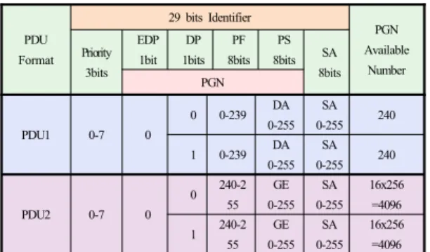
Table 2: The number of available PGN
PDU Format
29 bits Identifier
PGN Available
Number Priority
3bits EDP
1bit DP 1bits
PF 8bits
PS 8bits SA
8bits PGN
PDU1 0-7 0
0 0-239 DA
0-255 SA 0-255 240
1 0-239 DA
0-255 SA 0-255 240
PDU2 0-7 0
0 240-2 55
GE 0-255
SA 0-255
16x256
=4096 1 240-2
55 GE 0-255
SA 0-255
16x256
=4096
PGN of NMEA protocol is composed with EDP(Extended Data Page), DP(Data Page), PF(PGN Format), PS(PGN Specific). According to value of PF, PDU is largely divided into PDU1 and PDU2.
In case of PDU1, the number of available PGN is 480 because PF has unique value in this range. When PF has value between 240 and 255, PS expresses GE(General
Extension). Therefore, the number of available PGN in PDU2 is 8,192. Table 2 shows the number of available PGN each case.
3. Composition of system
3.1 Structure of composed system
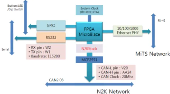
In this research, FPGA based u-Blaze was used for testing NMEA2000 protocol.
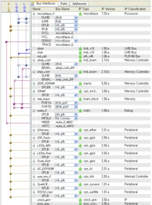
FPGA based u-Blaze is programmable logic elements and interconnects in semiconductor devices. FPGA based u-Blaze can have shorter development time and better error correction than conventional u-processor board. u-Blaze which was soft processor core was used to control memory and logic elements. Also, Virtex-4TM ML401 XC4VLX25 was used as evaluation board to make test bed for trial SoC[7-8]. CAN IP(Intellectual Property) was mounted on FPGA for CAN controller to communicate with CAN network, and UART IP was mounted for data monitoring through PC Hyperterminal[9].
Figure 1 shows structure of composed system bus with IP.
In order to communicate with CAN network, CAN clock must be 8 ~ 24 MHz, but system clock in ML401 is 100MHz.
Therefore, clock value in MHS (Microprocessor Hardware Specification) was set to 20MHz for matching CAN clock port using lock generator function. For transmitting and receiving CAN signal, extension port in ML401 was set up to transmit and receive each pin[7-9]. However, there is no CAN driver in ML401. The voltage level is different between ML401(3.3 or 5V) and CAN network(12V). Therefore, in order to solve these problems, MCP2551 as CAN
transceiver was mounted on previous extension port such as Figure 2. CAN high and low signal on MCP2551 are connected to NMEA2000 protocol stack on FPGA, and it can abstract NMEA2000 data from signal. Figure 3 shows whole composed system with FPGA and IP.
Figure 1: Structure of composed system bus with IP
Figure 2: Schematic diagram of CAN transceiver with ML401
Figure 4: Main routine in NMEA2000 stack Figure 3: Block diagram of mounted u-blaze and IP on
Virtex4 FPGA
3.2 NMEA2000 protocol stack
For NMEA2000 network communication, equipment needs to own SA. SA must be unique. If same SA exist on network, overlapped network devices have to adjust own SA. For this work, NMEA2000 protocol uses PGN59904 and PGN60928.
After POST(Power On Self Test), each equipment broadcasts PGN59904 on network, including device information and SA. During the broadcast, all network devices response to this request. Due to this task, each device can compare with other name filed value and priority. This task is called as address claim. When address claim occurs, network device should response within 250ms by PGN60928. If any devices do not response this time, they could ignore. In case of same SA, appropriate network device compares the priority of each device. If priority is same, it compares name field value. If name field value is higher than other, SA will be changed. This information is included in PGN60928.
Also, network device which changed SA runs address claim again. If each network device has own SA by this task, each device could send periodic data PGN, or request and response PGN to other device on the network. The major part of NMEA2000 stack is as follows Figure 4.
4. Experiment
4.1 Creation of PGN data
For verification of implemented NMEA2000 protocol stack, network communication connection and data are required. First of all, we mounted NMEA2000 protocol stack on ML401, and coded PGN127505 including fluid level data[6,10] in periodic function. Second, name field in PGN127505 includes fluid type based on each case. Table 3 appears hexadecimal value depending on fluid type. We chose three data types such as Fuel(0x00), Fresh Water(0x01), and Oil(0x04). ML401 could generate dummy random data about these types of fluid.
Table 3: Hexadecimal value depending on fluid type Hexadecimal value Fluid type
0x00 Fuel
0x01 Fresh Water
0x02 Waste Water
0x03 Live Well
0x04 Oil
0x05 Black Water(Sewage)
0x06 ~ 0x0D Reserved
0x0E Error
0x0F Data not available
4.2 Configuration of communication test
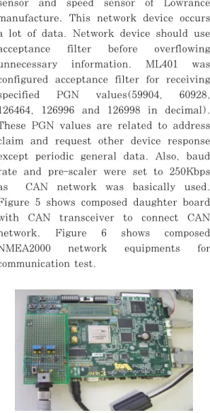
Actual configured ML401 was connected with already qualified equipments such as anemometer of Maratron, name of manufacture and fuel flow sensor, temperature
sensor and speed sensor of Lowrance manufacture. This network device occurs a lot of data. Network device should use acceptance filter before overflowing unnecessary information. ML401 was configured acceptance filter for receiving specified PGN values(59904, 60928, 126464, 126996 and 126998 in decimal).
These PGN values are related to address claim and request other device response except periodic general data. Also, baud rate and pre-scaler were set to 250Kbps as CAN network was basically used.
Figure 5 shows composed daughter board with CAN transceiver to connect CAN network. Figure 6 shows composed NMEA2000 network equipments for communication test.
Figure 5: Composed CAN transceiver board with ML401
Figure 6: Composed experiment equipments of NMEA2000 network
4.3 Communication test using PC Hyper-terminal For verification of data communication between ML401 and network, we used UART port on ML401 and PC Hyper- terminal. Because of acceptance filter in FPGA, ML401 only received the permitted PGN such as 59904, 60928 and others.
Figure 7 shows data field values whenever PGN value is 59904 or 60928. These PGN means address claim on network works well and ML401 has own unique SA.
Figure 7: Communication between composed NMEA2000 network equipments to PC
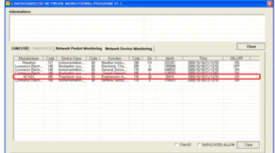
4.4 Network monitoring and data verification
For data verification, we made network monitoring program. This program shows device status including SA, network connection status, manufacture code, device class, identity value and others on real-time. In addition, we used CAN-to-USB converter to check real data from physical layer. Figure 8 shows actual network monitoring application and real network data. This picture confirms that the SA of ML401 is 30. Also, its identity is 92419. Indeed, according to manufacture code list from NMEA, manufacture value of ML401 is 345 defined as AITASC (Advanced IT And Ship Convergence center). This figure also shows other
devices such as equipments of Lowance and Maratron.
Figure 8: NMEA2000 protocol monitoring program
For verification real periodic data, we made monitoring application. This application can display information of connected device in NMEA2000 network.
Figure 9 shows navigation equipments data from Lowrance and Maratron. Figure 10 shows dummy data which comes from composed ML401 including level of fuel, fresh water and oil.
Figure 9: Navigation data
Figure 10: Engine and tank data
5. Conclusion
In this study, Tank level device was implemented with proposed NMEA 2000 protocol stack SoC which consists of CAN, UART and other peripherals including IP component and u-Blaze from Xilinx on existing NMEA2000 network to be composed of certified equipments. After address claim, composed ML401 with proposed NMEA 2000 protocol stack SoC sent periodic data PGN of fluid level data depending on each type. Through this experiment, possibility of SoC implementation was confirmed, and NMEA2000 stack was verified. In the future, USB, TCP/IP and others will be ported in FPGA as proposed method to make dedicated NMEA 2000 protocol stack SoC. Then, new integration system which can convert various communication protocol to NMEA2000 protocol will be developed.
Acknowledgement
This work was supported by the IT R&D program of MKE/IITA. [2008-F-046-01, Development of Core Technology of E-Navigation for IT Ship]
Reference
[1] Y.H. Yu, “Advanced IT ship technology analysis and prospect”, Journal of Institute of Electronics Engineers of Korea, vol. 35, no. 2, pp. 107-117, 2008.
[2] IMO Maritime safety committee 78th session - bridge design, equipment and arrangement submitted by the international association of classification societies(IACS), 2004.
[3] NMEA2000: Standard for Serial -
Data Networking of Marine Electronic Device, ver 1.20, 2004.
[4] ISO11783-3: Tractors and machinery for agriculture and factory-serial control and communication data network - Part3: Data link layer, 2007.
[5] ISO11898-1: Controller area network (CAN) - Data link layer and physical signalling, 2006.
[6] NMEA2000: Appendix B.1-PGN Table, ver 1.210, 2006.
[7] ML40x EDK processor reference design - User guide for EDK 8.1, 2006.
[8] ML401/ML402/ML403 evaluation platform - User Guide.
[9] H. Kim, “Real Xilinx Processor World”, Entmedia, 2005(in Korea).
[10] C.U. Lee, D.Y. Kim, Y.H. Yu and O.K. Shin, “Development of embedded vessel monitoring system using NMEA2000, Journal of Korean Society of Marine Engineering, vol. 33, no. 5, pp. 746-755, 2009.
Author Profile
Dong-Hyun Park
He received the B.E degree in IT Engineering from Korea Maritime University in 2009. He is a M.E.
student in Control and Instrumentation Engineering at Korea Maritime University in Busan. His research interests include ship standard network, ship material and SoC.
Ji-Tae Hong
He received the B.E degree in IT Engineering from Korea Maritime University in 2005. He received the M.S degree in Mechatronics Engineering from Pusan National University in 2007.
His research interests include embedded system and SoC.
Kyung-Yup Kim
He received the B.E degree in Electrical Engineering from Dong-A University in 1999. He received the M.E degree in Control and Instrumentation Engineering from Korea Maritime University in 2002, and Ph.D degree in Power & Control system from Dong-A University, Busan, in 2009. His research interests include estimation algorithm, signal processing, intelligent control and PC and micro-controller based data acquisition system.
Yung-Ho Yu
He received the B.E degree in Marine Engineering from Korea Maritime University in 1974. He received M.E and Ph.D degree Control Engineering from Korea Maritime University in 1986 and 1990. He is currently a professor in Dept. of IT Engineering at Korea Maritime University in Busan. His research interests include ship standard network, e-navigation system, ship material and embedded system.