Equivalency Assessment for an Eddy Current System Used for Steam Generator Tubing Inspection
Chan-Hee Cho*✝, Tae-Hun Lee*, Hyun-Ju Yoo* and Gyoon-Young Moon*
Abstract Eddy current testing is widely used for inspecting steam generator tubing in nuclear power plants (NPPs). The inspection technique for steam generator tubing in NPPs should be qualified in accordance with examination guidelines. When the components of a qualified system such as eddy current tester, probe, and data analysis program, are changed, the equivalency of the modified system to the originally qualified system must be verified. The eddy current tester is the most important part of an eddy current testing system because it excites and transmits alternating currents to the probe, receives coil impedance of the probe and generates signals for anomalies. The Korea Hydro & Nuclear Power Co., Ltd. (KHNP) developed an eddy current testing system with an eddy current tester and data acquisition-analysis program for inspecting the steam generator tubing in NPPs; this system can be used for an array probe and as a bobbin and rotating probes. The equivalency assessment for the currently developed system was carried out, and we describe the results in this paper.
Keywords: Equivalency Assessment, Eddy Current Testing, Nondestructive Examination, Steam Generator Tubing
[Received: July 1, 2015, Revised: August 12, 2015, Accepted: August 12, 2015] *KHNP-Central Research Institute, Daejeon 305-343, Korea, ✝Corresponding Author: Korea Hydro & Nuclear Power Company Ltd., Central Research Institute, Daejeon, 305-343, Korea (E-mail: [email protected])
ⓒ 2015, Korean Society for Nondestructive Testing
1. Introduction
Utilities should use the qualified techniques when performing eddy current tests (ECT) for the inspection of steam generator tubing. The qualified techniques are listed on the perform- ance demonstration database in the form of examination technique specification sheet (ETSS) in the Electric Power Research Institute (EPRI) documents, and their requirements are described in the EPRI steam generator(SG) examination guidelines [1]. The EPRI SG examination guidelines require that each ETSS define essential variables for equipment, technique, and data analysis such as eddy current tester, probe, cable, tube material, acquisition and analysis program, calibration standard, sampling rate, and analysis procedure, etc. Examination techniques with essential variables that vary within the ranges specified in the ETSS are considered equivalent. The KHNP developed an eddy
current testing system for the inspection of SG
tubes. This system includes eddy current tester,
probe push-puller control system, and data
acquisition-analysis program. The eddy current
tester is composed of synthesizer, analog
processor, and analog-to-digital conversion
board. It excites alternating currents, senses coil
impedance variation of the probe and produces
the eddy current signal. The probe push-puller
system is used to move the bobbin, rotating,
and array probes for the data acquisition. The
acquired data are analyzed by the qualified data
analysts using data analysis program in order to
identify whether a tube includes flaws [2]. The
currently developed data acquisition-analysis
programs are based on the Windows operating
system, while the previously used programs are
on the Unix-based. The equivalency assessment
for the currently developed system was carried
out and the results were explained in depth in
this paper.
2. Equivalency Requirements
2.1 ECT System Developed by KHNP
There have been some degradation mech- anisms on SG tube walls in the nuclear power plant such as pitting, wear, impingement, and stress corrosion cracking, etc. [2]. For the detection of flaws on tube walls, the eddy current testing is used because it offers a relatively low cost approach for high speed, large scale testing of metallic materials in high pressure and temperature engineering systems.
The ZETEC eddy current testing systems [3]
like MIZ-70, which were qualified in the EPRI ETSS, have been widely used in many countries including Korea, Japan and the U.S. The KHNP developed an eddy current testing system for the inspection of SG tubes. This system is composed of not only hardware such as fixture controller, eddy current tester and probe push-puller control system as shown in Fig. 1, but also software for data acquisition and analysis.
The remote fixture is installed in the SG chamber for positioning of the probe. The fixture controller makes the probe locate correctly and accurately on the spot of the tube end which is to be inspected based on the test plan. The eddy current tester comprises a central processing unit, a frequency synthesizer, an analog processor, and an analog to digital converter. It performs all testing functions including wide-range frequency generation, in-phase, and quadrature signal digitization.
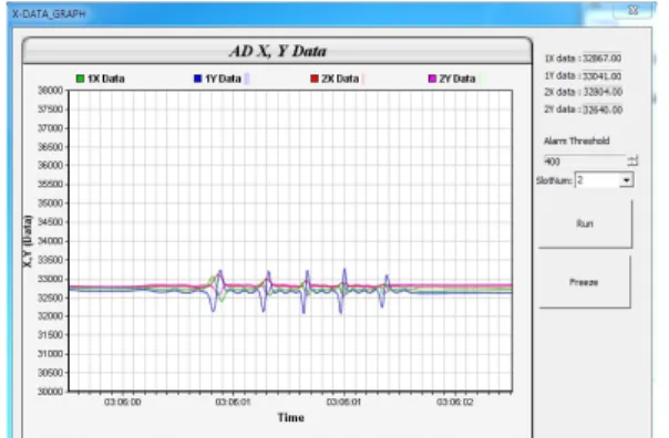
Basic specifications of the KHNP eddy current tester are the same as the MIZ-70, for instance, 10 Hz to 10 MHz of frequency range, 0 to 20 V of drive voltage, 0 to 23 dB of gain, and 16-bit of A/D resolution. Fig. 2 shows the front and rear view of the KHNP eddy current tester and its X-Y axes signals for the calibration standard are shown in Fig. 3.
Fig. 1 Eddy current testing system for SG tubing inspection
Fig. 2 Front and rear views of the KHNP eddy current tester
Fig. 3 X-Y signals of the calibration standard obtained from the KHNP eddy current tester
The probe push-puller control system
includes motion control circuitry which allows
precise control of the probe’s travel speed and
provides smooth transition between low- and
high-speeds without time consuming gear
changes. The data acquisition program provides
the functions of fixture movement, adjustment of
guide-tube location, probe movement, and data
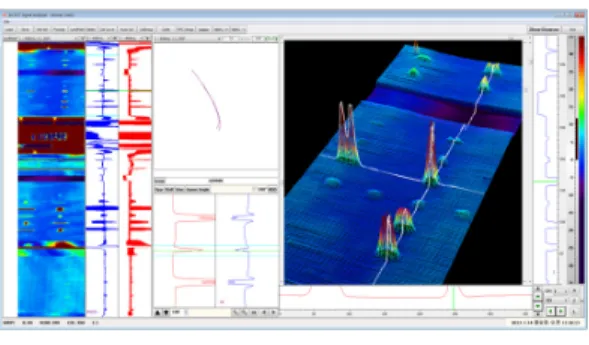
Fig. 4 An example of flaw signals in data analysis program
storage. Flaw detection and sizing for bobbin, rotating, and array probe data can be obtained by analyzing signals from the data analysis program. It also allows the comparison for two separate analysts’ results and resolution of their discrepancies [2]. An example of flaw signals from the data analysis program of the currently developed system is shown in Fig. 4.
2.2 Equivalency Requirements for Examination Technique
The qualified techniques for SG tube inspection are listed on the EPRI performance demonstration database in the form of ETSS as described above. An ETSS defines essential variables for equipment, technique, and analysis procedure such as eddy current tester, tube material, probe type, probe length, frequency, gain, sample rate, test speed, calibration standard, and data acquisition and analysis programs, etc. When components of a qualified system are changed, verification of equivalency to the originally qualified system must be performed[4]. Examination techniques with essential variables that vary within the ranges specified in the ETSS are considered equivalent.
Tolerances were categorized from the EPRI equivalency project are as follows[4]:
For bobbin techniques, (1) The amplitude voltage response from the 4×20% trough-wall flat-bottom holes (TW FBHs) must be greater
than or equal to 80% of the raw signal response from the qualified technique. (2) All normalized FBH responses must be within ±40% of the qualified technique. (3) If the tube diameter is the same as that in the qualified technique, then the normalized amplitude voltage response of the 100% deep TW hole must be within ±40%
of the qualified technique. (4) the phase angle responses of the FBH and TW hole flaws must be within 20 degrees (±20 degrees).
For rotating probe techniques, (1) the non-normalized amplitude voltage response from the 100% TW hole by 0.375 inches (9.5 mm) long axial notch must be greater than or equal to 80% of the raw signal response from the qualified technique. (2) All normalized notch amplitude voltage responses (0.375 inches long, ID and OD 40%, 60%, 100% TW) must be within ±20% of the qualified technique. (3) The phase angle responses of the electric discharge machining(EDM) notches must be within 10 degrees (±10 degrees).
Tolerances for the array probe technique are not established yet, therefore the equivalency assessment for the array probe technique is not included in this paper.
3. Assessment Results
The equivalency assessments for the currently developed eddy current testing system (the KHNP system) were performed. The qualified EPRI ETSS 96007.1 for the bobbin probe technique and the ETSS 21410.1 for the rotating probe technique were chosen for the assessments, which have been used in the field inspection of SG tubes in many countries [4]. In this study, the upgraded version MIZ-70 of the MIZ-18 in the qualified ETSS and the KHNP eddy current tester were used for the equivalency assessment.
The same essential variables including the probe
were used in the assessment except eddy current
tester and data acquisition and analysis programs.
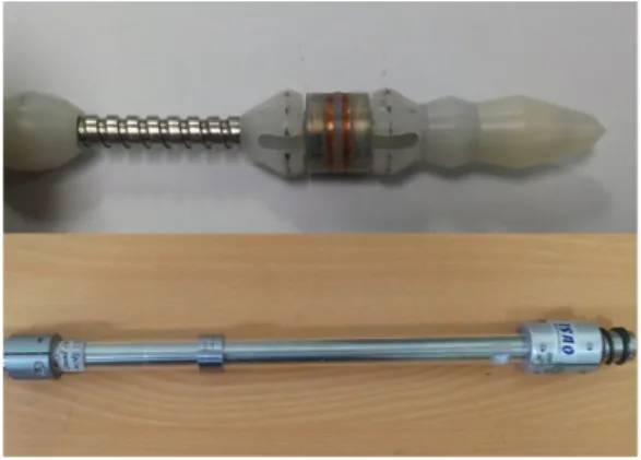
Fig. 5 Bobbin probe and ASME calibration standard
3.1 Bobbin Probe Technique
The ETSS 96007.1 used in the assessment for the bobbin probe technique has been applied for the detection of inter-granular attack/outside diameter stress corrosion cracking(IGA/ODSCC) at non-dented drilled tube support plates[4].
Table 1 shows the comparison for the essential variables of the ETSS 96007.1 and the KHNP system.
Table 1 Essential variables of the ETSS 96007.1 and the KHNP system
Essential Variables
ETSS 96007.1
KHNP System Tube
Material I-690 I-690
Tube OD (in) 0.750 0.750
Tube wall (in) 0.043 0.043 Relative
current density
22.24@550 kHz 45.61@150 kHz
22.24@550 kHz 45.61@150 kHz
Coil space (in) 0.06 0.06
Probe Bobbin MR Bobbin MR
Eddy current
tester MIZ-70 KHNP
Acquisition
software ZAC KHNP-ACQ
Analysis
software Eddynet KHNP-ANA
Probe
manufacturer ZETEC ZETEC
Probe type MULC MULC
Fill factor (%) 84 84
Frequency
(kHz) 550/150 550/150
Volts/Gain 12/0.5 12/0.5
Sample rate 40 40
Test speed
(in/sec) 40 40
Test direction Pull Pull
Analysis
software HP c3750 PC
Calibration
standard ASME ASME
The relative eddy current density is calculated using the following approximation equation:
(1)
where J(x) is the eddy current density at location x inside the conducting tube wall and J
0is the magnitude of the eddy current density on the surface of the tube wall closest to the probe coil. The eddy current skin depth of penetration δ is expressed by Eq.(2) as follows:
(2)
where f is the operating frequency, ρ is the electrical resistivity of the material and μ is the magnetic permeability of the material.
The bobbin probe and the ASME calibration standard used in the assessment are shown in Fig. 5.
The results of the equivalency assessment for the bobbin probe technique are shown in Table 2 and Fig. 6 to Fig. 11. In Table 2, P_P uses the peak-to-peak value to calculate both the volts and phase measurement[2]. MxR measures the maximum rate of change for the phase value of small set of vector points in signal[2]. Diff.
Mix denotes differential mix of two signals.
There are two modes in eddy current testing,
absolute and differential mode. An absolute coil
Table 2 Results of the equivalency assessment for bobbin probe technique between the ETSS 96007.1 and the KHNP system
Flaws Frequency (kHz) ETSS 96007.1 KHNP System Ratio/Difference 4×20% FBH
Non-normalized
Volts (P_P)
550 150
7.43 V 17.87 V
7.69 V 17.95 V
103%
100%
4×20% FBH Normalized
550/150
Diff. Mix 4.00 V 4.00 V 0%
40% FBH Normalized
550/150
Diff. Mix 4.34 V 4.61 V 6%
60% FBH Normalized
550/150
Diff. Mix 6.46 V 6.78 V 5%
100% TWH Normalized
550/150
Diff. Mix 7.01 V 7.10 V 1%
4×20% FBH Normalized
Phases (MxR)
550/150
Diff. Mix 122° 122° 0°
40% FBH Normalized
550/150
Diff. Mix 106° 105° -1°
60% FBH Normalized
550/150
Diff. Mix 88° 85° -3°
100% TWH Normalized
550/150
Diff. Mix 35° 35° 0°
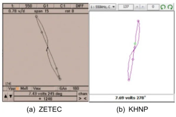
(a) ZETEC (b) KHNP
Fig. 6 Raw 550 kHz bobbin differential signals of 4×20% FBHs
(a) ZETEC (b) KHNP
Fig. 7 Raw 150 kHz bobbin differential signals of 4×20% FBHs
responds to the electromagnetic properties of the
test object in the magnetic field of the coil
without comparison to response of a second
coil. Differential coils are two coils connected in
such a way that electromagnetic differences in
the regions beneath the coils will cause an
imbalance between them to be signaled. A
problem of the absolute eddy current probe is
the difficulty of detecting small changes in
impedance, which are superimposed over the
value in air. In addition, changes in the coil
parameters because of environmental factors and
liftoff can often mask changes due to
discontinuities, making signal interpretation very
difficult. An alternative to the absolute eddy
current probe is the differential eddy current
probe. The probe consists of two identical coils
mounted on the same axis as the tube but
spaced apart by a small distance. The two coils
from two arms of a bridge circuit. The bridge
imbalance signal is the voltage difference across
the impedance of two coils. The mix of two
differential signals in different frequencies is
(a) ZETEC (b) KHNP
Fig. 8 Normalized 550/150 kHz bobbin differential signals of 4×20% FBHs
(a) ZETEC (b) KHNP
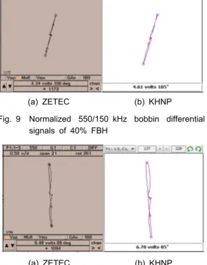
Fig. 9 Normalized 550/150 kHz bobbin differential signals of 40% FBH
(a) ZETEC (b) KHNP
Fig. 10 Normalized 550/150 kHz bobbin differential signals of 60% FBH
(a) ZETEC (b) KHNP
Fig. 11 Normalized 550/150 kHz bobbin differential signals of 100% TWH
Fig. 12 Rotating probe and EDM-notch calibration standard
used to remove the tube support signal for facilitating detection of flaws.
As shown in Table 2 and Fig. 6 to Fig. 11, the KHNP system is satisfied with the four requirements for the bobbin probe technique.
The amplitude voltage responses of 4×20% TW FBHs for the KHNP system are 103% at 550 kHz and about 100% at 150 kHz of those for the ETSS 96007.1. Differences of all normalized amplitude responses for the KHNP system are within 7% of the qualified technique.
The normalized amplitude response of the 100%
TWH is almost same as that of the qualified technique. The results also show that the phase angle responses of the FBH and TWH flaws for the KHNP system are within ±% of the qualified technique.
3.2 Rotating Probe Technique
The ETSS 21410.1 used in the assessment for the rotating probe technique has been applied for the detection of circumferential ODSCC at transition region of tubesheet[4].
Table 3 shows the comparison for the essential variables of the ETSS 21410.1 and the KHNP system. The rotating probe and the EDM notch calibration standard used in the assessment are shown in Fig. 12.
The results of the equivalency assessment for
the rotating probe technique are shown in Table
4 and Fig. 13 to Fig. 22. In Table 4, SAI
stands for single axial indication and SCI
denotes single circumferential indication.
As shown in Table 4 and Fig. 13 to Fig.
22, the KHNP system is satisfied with the three requirements for the rotating probe technique.
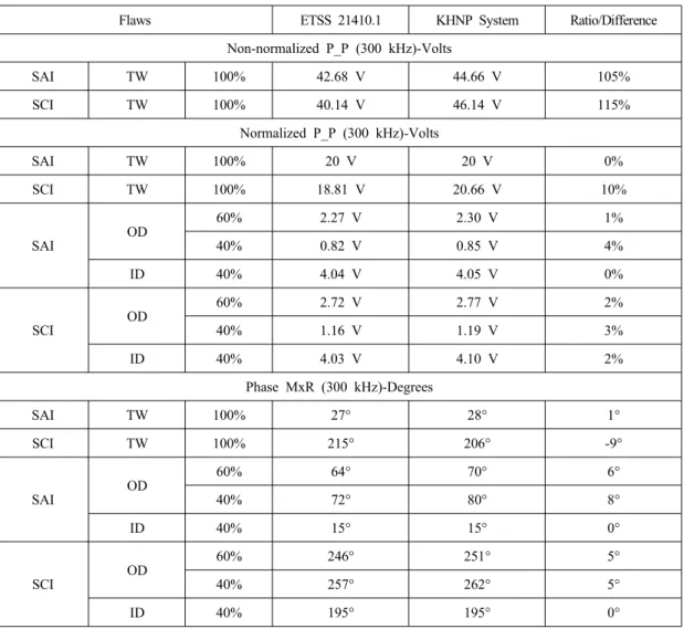
The non-normalized amplitude voltage response from the 100% single axial notch for the KHNP system is 105% of the qualified technique. The ratio of all normalized notch amplitude voltage responses for the KHNP system to the qualified system is within 5%. The differences between the KHNP system and the qualified technique for the phase angle responses of the EDM notches are within ±10%.
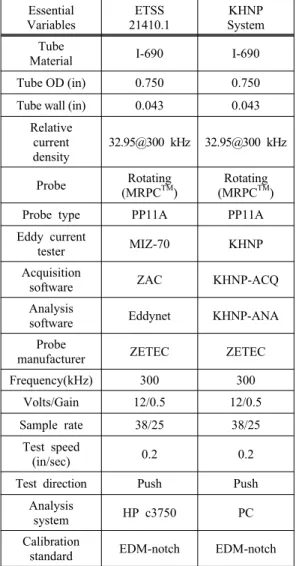
Table 3 Essential variables of the ETSS 21410.1 and the KHNP system
Essential Variables
ETSS 21410.1
KHNP System Tube
Material I-690 I-690
Tube OD (in) 0.750 0.750
Tube wall (in) 0.043 0.043 Relative
current density
32.95@300 kHz 32.95@300 kHz
Probe Rotating
(MRPCTM)
Rotating (MRPCTM)
Probe type PP11A PP11A
Eddy current
tester MIZ-70 KHNP
Acquisition
software ZAC KHNP-ACQ
Analysis
software Eddynet KHNP-ANA
Probe
manufacturer ZETEC ZETEC
Frequency(kHz) 300 300
Volts/Gain 12/0.5 12/0.5
Sample rate 38/25 38/25
Test speed
(in/sec) 0.2 0.2
Test direction Push Push
Analysis
system HP c3750 PC
Calibration
standard EDM-notch EDM-notch
(a) ZETEC (b) KHNP
Fig. 13 Raw 300 kHz +point signals of 100% axial notch
(a) ZETEC (b) KHNP
Fig. 14 Raw 300 kHz +point signals of 100%
circumferential notch
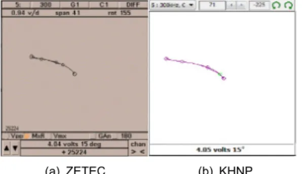
(a) ZETEC (b) KHNP
Fig. 15 Normalized 300 kHz +point signals of 100% axial notch
(a) ZETEC (b) KHNP
Fig. 16 Normalized 300 kHz +point signals of 100% circumferential notch
(a) ZETEC (b) KHNP (a) ZETEC (b) KHNP Fig. 17 Normalized 300 kHz +point signals of
60% OD axial notch
Fig. 18 Normalized 300 kHz +point signals of 40%
OD axial notch
Table 4 Results of equivalency assessment for rotating probe technique between the ETSS 21410.1 and the KHNP system
Flaws ETSS 21410.1 KHNP System Ratio/Difference
Non-normalized P_P (300 kHz)-Volts
SAI TW 100% 42.68 V 44.66 V 105%
SCI TW 100% 40.14 V 46.14 V 115%
Normalized P_P (300 kHz)-Volts
SAI TW 100% 20 V 20 V 0%
SCI TW 100% 18.81 V 20.66 V 10%
SAI OD 60% 2.27 V 2.30 V 1%
40% 0.82 V 0.85 V 4%
ID 40% 4.04 V 4.05 V 0%
SCI OD 60% 2.72 V 2.77 V 2%
40% 1.16 V 1.19 V 3%
ID 40% 4.03 V 4.10 V 2%
Phase MxR (300 kHz)-Degrees
SAI TW 100% 27° 28° 1°
SCI TW 100% 215° 206° -9°
SAI OD 60% 64° 70° 6°
40% 72° 80° 8°
ID 40% 15° 15° 0°
SCI OD 60% 246° 251° 5°
40% 257° 262° 5°
ID 40% 195° 195° 0°
(a) ZETEC (b) KHNP
Fig. 19 Normalized 300 kHz +point signals of 40%
ID axial notch
(a) ZETEC (b) KHNP
Fig. 20 Normalized 300 kHz +point signals of 60%
OD circumferential notch
(a) ZETEC (b) KHNP
Fig. 21 Normalized 300 kHz +point signals of 40%
OD circumferential notch
(a) ZETEC (b) KHNP
Fig. 22 Normalized 300 kHz +point signals of 40%
ID circumferential notch