음이온 기반 멤리스터의 최신 기술동향 및 이슈
이홍섭† 강원대학교 재료공학과
The Latest Trends and Issues of Anion-based Memristor
Hong-Sub Lee†
Department of Materials Science & Engineering, Kangwon National University, 1 Kangwondaehak-gil, Chuncheon-si, Gangwon-do 24341, Korea
(Received March 1, 2019: Corrected March 26, 2019: Accepted March 28, 2019)
Abstract: Recently, memristor (anion-based memristor) is referred to as the fourth circuit element which resistance state can be gradually changed by the electric pulse signals that have been applied to it. And the stored information in a memristor is non-volatile and also the resistance of a memristor can vary, through intermediate states, between high and low resistance states, by tuning the voltage and current. Therefore the memristor can be applied for analogue memory and/or learning device. Usually, memristive behavior is easily observed in the most transition metal oxide system, and it is explained by electrochemical migration motion of anion with electric field, electron scattering and joule heating. This paper reports the latest trends and issues of anion-based memristor.
Keywords: Memristor, Analog memory, Crossbar array architecture, Sneak current, Linearity
1. Introduction
수동소자를 구성하는 기본요소인 resistor, capacitor, inductor에 이은 네 번째 구성요소로 구분되고 있는 memristor는 memory와 resistor의 합성어로 재료가 저항 을 바꾸고 그 상태를 기억하는 재료를 말한다.1) 외부에서 전압이 가해지면 재료의 상태 변화가 발생하고 결과적으 로 저항이 바뀌는 재료에 대하여 memristor로 통칭하므로 최근 그 용어의 사용이 ferroelectric tunnel junction, spin- torque transfer, ionic-based, phase change materials로 확장되 어 가고 있다.2-5) 과거 이러한 재료의 상태변화 특성을 이 용하는 응용분야로 차세대 비휘발 메모리가 대표적으로 ferroelectric random access memory (FeRAM), ferroelectric field effect transistor memory (FeFET memory), phase change RAM (PCRAM), spin-toque transfer magnetic RAM (STT-MRAM), resistive RAM (ReRAM) 등이 있다.6-10)이 러한 차세대 비휘발 메모리 후보 중 memristor를 이용하 는 ReRAM은 빠른 switching 속도(1 µm~100 ns) 와 큰 on/
off ratio (10~103) 로 2000년대 초반부터 활발히 연구되기 시작하였다.11-13) 위 차세대 비휘발 메모리 후보에서 알 수
있듯 차세대 비휘발 메모리는 기존 dynamic RAM (DRAM)과 not and (NAND) flash memory의 charge trap 방
식과14,15) 달리 재료의 상태변화를 이용하는 메모리로서
차세대 비휘발 메모리 개발에 있어 재료의 물성 및 공정 이 매우 중요한 요소임에 틀림이 없다. 위의 후보 중 STT- MRAM을 제외하면 모두 재료의 상태변화 과정에 이온 의 displacement 또는 migration이 필요하며 이는 신뢰성 및 반복기록 횟수에 단점으로 작용하게 된다. 많은 연구 자들의 노력에도 불구하고 현재까지 몇 가지의 기술적 이 슈들이 아직 남아 있으며, 그 사이 V-NAND memory의 상용화로 인하여 NAND flash memory가 집적도 이슈에 서 벗어남으로써 위의 메모리들의 경쟁력이 한층 약화된 면이 있으나 ReRAM의 경우 속도 및 집적도 면에서 아 직 강점을 가지고 있다. 또한 최근 memristor의 analog memory 특성을 이용한 뉴로모픽 컴퓨팅소자와 같은 새 로운 응용분야가 개발됨으로써 활발히 연구가 진행되고 있다. 본고에서는 위의 다양한 memristor 중 음이온 기반 memristor의 기본 컨셉과 최신 기술동향 및 이슈들에 대 하여 소개하고자 한다.
†Corresponding author
E-mail: [email protected]
© 2018, The Korean Microelectronics and Packaging Society
This is an Open-Access article distributed under the terms of the Creative Commons Attribution Non-Commercial License(http://creativecommons.org/
licenses/by-nc/3.0) which permits unrestricted non-commercial use, distribution, and reproduction in any medium, provided the original work is properly cited.
특집 : 차세대 수동소자 멤리스터
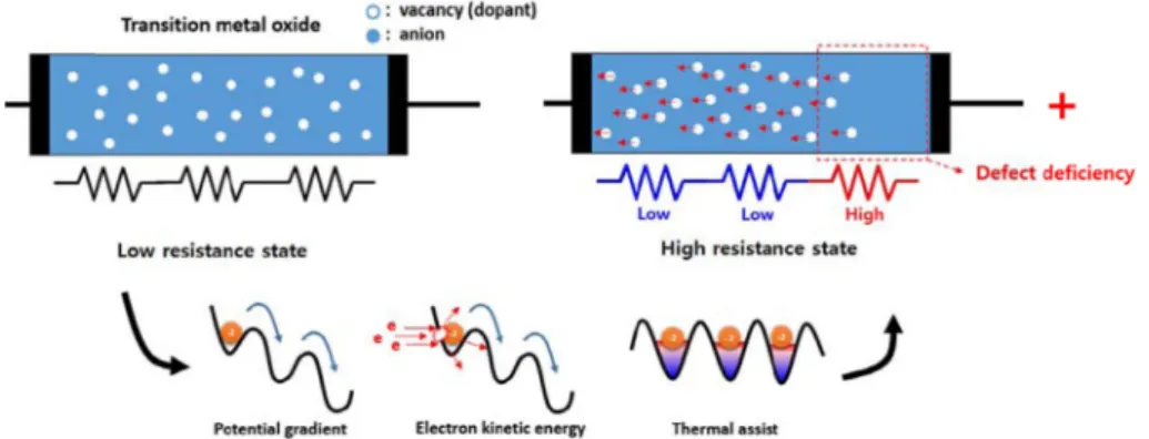
Joule heating에 의해 산소음이온이 Fig. 1(우)에서와 같이 전이금속 산화물 안에서 우측으로 이동하게 되고, 이 경 우 산소 공공이 많은 영역과 적은 영역으로 불균형이 발 생하게 된다. 이 경우 산소공공이 많아진 영역은 low resistance state (LRS), 산소공공이 적어진 영역은 high resistance state (HRS)로 변화하게 될 것이며, 결과적으로 Fig. 1의 전극/전이금속산화물/전극 구조를 직렬저항으로 고려하였을 때 총 저항은 증가하게 된다. 이과정은 가역 적 반응으로 음의전압으로 다시 LRS 로 되돌릴 수 있다.
과거에는 전이금속 산화물 하나의 저항을 고려하였다면, memristor 에서는 Fig. 1의 전이금속 산화물을 여러 개의 저항체의 집합체로 고려한다.
Fig. 2는 이러한 Fig. 1의 과정을 통하여 나타나는 I-V 특성을 나타낸다. 양의 전압에서 HRS로 switching이 발 생하며 음의 전압에서 LRS 로 switching이 발생한다.
일반적으로 이러한 저항변화 효과는 Fig. 3과 같이 국 부적영역에서 나타나는 filament type과 (좌) 전극과의 계 면 전체를 고려하는 interface type (우) 두 가지 대표적 저 항변화 mechanism이 보고되어 있다. Filament type의 경 우 compliance current를 잡아준 후 고전압을 인가하면 soft breakdown에 의한 filament를 형성할 수 있는데 (forming process) 이렇게 형성된 filament가 두 전극사이에서 conduction bridge 역할을 하며, 이 conducting filament가 외
부 인가전압에 의해 국부적으로 소실 회복됨으로써(산소 이온의 이동) switching 역할을 한다. Interface type의 경 우 외부인가 전압에 의해 박막내부에 존재하는 산소공공 들이 electrochemical migration을 함으로써 switching이 발 생하는데 산소이온의 경우 –2의 effective charge를 띄고 있 으므로 인가전압의 극성에 따라 electrochemical migration 방향이 결정된다. 이로 인하여 산소공공이 계면에 축적 될 경우 계면부의 Schottky like barrier의 에너지 장벽이 나 depletion region의 길이가 변화하게 되어 저항변화 효 과를 얻을 수 있다.
2.2. Issues: reliability, operating current, sneak current Memristor는 간단한 2 terminal 구조 덕분에 Fig. 4와 같 이 crossbar array 구조의 고집적도의 메모리소자의 제작 이 가능하며 동시에 빠른 switching 속도와 저 전압에서 동작이 가능하므로 NAND flash memory를 대체할 차세 대 비휘발 메모리(ReRAM)로 많은 기대와 함께 연구되어 왔으나, 현재까지 몇가지의 기술적 이슈들이 남아있다. 그
Fig. 1. Conceptual schematic of resistive switching mechanism of memristor.
Fig. 2. Typical I-V characteristic of memristor. The numbers indicate switching sequence. (reprinted with permission from [13], Springer Nature).
중 대표적인 이슈인 reliability, operating current, sneak current에 대해 소개하고 이를 해결하기 위해 최근 발표 된 연구 사례를 소개하고자 한다.
Reliability: Fig. 1에서 기술한 바와 같이 memristor의 저 항변화 특성은 electrochemical migration에 의한 것으로 on/off 동작을 위해 많은 양의 이온이 반복하여 이동해야 만 한다. 메커니즘 상 반복적으로 switching하는 과정에 서 매번 같은 on (off) 저항 값을 얻고자 한다면 같은 양 의 음이온(또는 산소공공)이 반복하여 유사한 위치를 이 동하여야 한다. 실제 switching 동작을 여러 번 반복측정 을 하게 되면 switching 전압과 on (off) 저항 값이 항상 같 지 않고 산포도를 가지는 것을 볼 수 있다. 또한 산소공 공의 반복되는 이동 과정에서 공공들 간의 clustering 또 는 ordering이 발생하게 되어 이들은 더 이상 움직이지 못 하게 되고 on/off ratio는 감소 후 사라지게 되어 endurance 특성을 저해하게 된다.
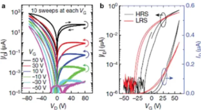
Fig. 1의 메커니즘 모식도는 한쪽(오른쪽) 계면만을 고 려하고 있다. 오른쪽 전극에 양의 전압을 가하였을 때 HRS로의 switching이 발생하고 음의 전압을 가하였을 때 LRS로 돌아가는 것이다. 하지만 반대로 음의 전압을 먼 저 가해주었다고 가정하였을 때 왼쪽 계면에 산소이온이 쌓이게 되고 HRS로 switching이 발생할 수 있다. 일반적 으로 metal substrate 위에 박막형태로 소자를 제작하여 상 부전극만 패턴 할 경우 하부전극과의 계면은 상대적으로 넓고 상부전극과의 계면은 작기 때문에 주로 상부전극과 의 계면에서의 switching 이벤트만 고려할 수 있으나 실 제 소자를 array하기 위해서는 상하부 전극을 모두 패턴 해야 하므로 같은 크기의 두 계면에서 switching 이벤트 가 발생할 수 있다(같은 상.하부 전극물질을 사용하는 경 우). 이 경우 Fig. 4와 같이 한쪽 바이어스에서 HRS -> LRS -> HRS 두 번의 switching 이벤트가 관찰되는데 이를 complementary switching이라하며, 저 전압에서 저 전류 구간을 얻을 수 있다. 이는 뒤에 기술할 sneak current 이
슈를 보완하는데 유용하게 사용될 수 있다.16-18)
Operating current: 위의 Fig. 1과 같이 memristor에 전압 이 인가되면 electric field, electron scattering, Joule heating 에 의해 electrochemical migration이 발생하고 저항변화가 발생하게 된다. HRS에서 LRS로의 switching은 electric field에 의존하지만, LRS에서 HRS로의 switching은 전류 량에 의존하게 된다. 따라서 전류량이 작으면 가역적 switching이 어렵게 되는데 현재의 CMOS는 memristor 를 구동하기에 전류량이 작기때문에 µA 이하에서 on/off가 가능한 재료의 개발이 필요하다.
Sneak current: memristor의 저항변화 특성을 이용하는 ReRAM은 높은 집적도를 구현하기 위해 crossbar array 구 조의 구현이 필요하다. Fig. 5(a)의 crossbar array 구조의 경우 각 셀 당 셀 선택 transistor 없이 비트라인과 워드라 인을 이용하여 동작하기 때문에 높은 집적도를 얻을 수 있으며 적층을 통하여 용량을 증가시키기에 용이하다.
Fig. 3. Conceptual schematic of representative resistive switching mechanism of filament type and interface type. Arrows colors of each bias correspond to directions of oxygen anion migration.
Fig. 4. Complementary switching curve. (reprinted with permission from [16], Springer Nature).
Fig. 5(a) 우측 그림은 4개의 셀을 확대해 놓은 그림으로 읽고자 하는 셀을 붉은 색으로 표현하였을 때 그림과 같 이 Vread를 전압을 인가하게 된다. 이 경우 Fig. 5(b)와 같이 병렬회로로 고려되며 선택되지 않은 주변 셀 들을 통하여 전류가 흘러 들게 되는데 이를 sneak current라 한다.19) 이 로 인하여 선택한 셀의 정확한 저항 값을 읽기 어려워 지 는데 이를 최소화 하고자 Fig. 5(a) 우측 그림과 같이 선 택하지 않은 셀들의 word line에 1/2Vread를 가해 주게 된다. 이 경우 그림 5(b)와 같이 sneak path에 인가되는 전 압이 줄어들게 되어 sneak 전류를 줄일 수는 있으나, sneak current는 array size가 증가와 함께 증가하기 때문에 이 sneak current는 array size를 제한하는 원인이 된다.
이를 해결하기 위하여 Fig. 6과 같이 저 전압 구간에 저 전류 구간을 만들 수 있는 complementary switching과 정 류 구간을 만들기 위한 diode 또는 potential barrier를 삽입 하는 시도가 되었으나 diode, potential barrier층의 voltage drop에 의해 memristor가 switching에 필요한 충분한 전압 을 받지 못하거나 충분한 전류가 흐르지 못하여 switching ratio가 줄어드는 문제가 발생한다.18-21) Mott metal- insulator transition 재료를 연결하여 정류구간을 만드는 방 안이 시도되었으나 필요한 정류구간의 전류량을 충분히
낮추어 주지 못하는 어려움이 있다. 이렇듯 sneak current 이슈를 해결하기에 어려워 최근 memristor의 analog memory 특성을 이용한 unsupervised learning 소자의 concept가 발표되었다. Unsupervised learning은 기존 메모 리는 결과값을 정해 놓고 이에 맞추어 쓰기동작을 하였 지만, crossbar array architecture에서는 sneak current 문제 로 인하여 목표하는 셀에 정확한 값을 쓰거나 읽는 것에 어려움이 있으므로 쓰기동작만을 정해준 후 여러 번의 학 습(반복하여 쓰기동작) 후 sneak current를 포함하여 읽히 는 값을 측정하여 쓰기동작과 결과값을 매칭한다.
3. Analog characteristic and the new application of memristor
앞에서 기술한 바와 같이 음이온 기반 memristor는 인 가된 전압에 의한 산소이온의 이동에 의해 저항변화 특 성을 나타낸다. 따라서 인가된 전압의 크기, 시간, 횟수에 따라 점차적으로 저항을 변화시킬 수 있다. 적절한 크기 의 pulse를 사용하면 인가된 pulse 횟수에 따라 여러 개의 저항상태를 만들 수 있어 analog 메모리 특성을 구현할 수 있다. (gradual LRS (HRS) switching을 potentiation Fig. 5. a) Schematic diagram of crossbar array architecture, b) circuit diagram of 2 x 2 crossbar array architecture. (reprinted with
permission from [19], Springer Nature).
Fig. 6. Solutions for sneak current issue.
(depression)이라 함) 이를 CMOS와 함께 사용할 경우 기 존 디지털 논리소자가 아닌 analog 논리소자의 구현이 가 능하여 학습소자 또는 인공지는 소자를 구현하는데 매우 효과적이다. 현재 10개 이상의 구별되는 상태의 구현이 가능한 경우 analog memory로 보고 있다. Floating gate 또 한 multi-bit 저장이 가능하여 analog 논리소자 및 학습소 자 구현에 있어 유용하나 높은 쓰기전압과 쓰기횟수 제 한, 상대적으로 느린 쓰기속도로 인한 어려움이 있다. 따 라서 memristor가 유리한 측면이 있으나 CMOS와 결합하 여 circuit을 design 할 경우 potentiation/depression curve의 asymmetric 문제가 발생한다. Fig. 7(a)는 같은 크기의 positive pulse, negative pulse를 사용하였을 때 이상적인 potentiation/depression curve를 가상의 그래프로 나타냈다.
CMOS와 결합하여 소자를 구동하기 위해서는 같은 크기 의 positive pulse, negative pulse에 동일하게 반응해야 하 지만 일반적으로 memristor는 그림 7(b)와 같이 비대칭의
switching curve를 보여준다. Memristor는 HRS에서 LRS로 switching은 전압에 의존하고 LRS에서 HRS으로의 switching은 전류량에 의존하기 때문에 이러한 asymmetric 특성이 나타난다. 또한 그림과 같이 실제 memristor는 비 선형의 저항변화 거동을 나타내는데 이는 memristor resistive switching mechanism으로 기인하지만, 적절한 크 기의 펄스를 적절한 횟수로 제한하여 인가할 경우 극복 이 가능하다.
4. Latest trend of memristor
4.1. Operating current issue: ultra-small memristor 앞서 기술한 동작전류 이슈를 해결하기 위해 전극면적 을 최소화하기 위한 시도가 되고 있다. 전극 면적을 줄이 게 되면 형성되는 filament의 크기 또한 제한하는 효과를 얻을 수 있다. Fig. 8은 최근 Qiangfei Xia group에서 발표 한 연구결과로 2.2 nm 폭의 전극을 이용하여 동작전류를 획기적으로 줄일 수 있었다. 또한 sneak current를 제한하 기 위하여 TiOx/HfO2 bilayer 구조를 도입함으로써 diode 형태의 3 x 3 crossbar array 구조의 memristor 소자를 구 현하였다.
4.2.Reliability and linearity issue: filament control (remote epitaxy)
Fig. 9은 최근 Jeehwan Kim group이 발표한 연구 결과 로 저자들은 박막형태의 memristor에 형성되는 filament Fig. 7. Virtual potentiation/depression characteristics: a) ideal
curve, b) real curve.
Fig. 8. a) a representative TEM image of a 3 × 3 memristor crossbar array with 2 × 2nm2 device area and with sub-12-nm pitch. b) a typical I–V curve for a 2-nm Pt/TiOx/HfO2/Pt memristor in the array. c) Simulated electric field distribution in 2-nm memristor crossbars with the centre cell selected are plotted for a cross-sectional view along the bottom electrode direction. (reprinted with permission from [22], Springer Nature).
Fig. 9. a) a conceptual schematic of the epiRAM during switching. b) cross-sectional TEM image of 60nm SiGe grown on a Si substrate.
Scale bar, 25 nm c) cross-sectional SEM image of an epiRAM device. (reprinted with permission from [23], Springer Nature).
를 제어하고자 remote epitaxy 기술을 이용하여 SiGe epiRAM 소자를 구현하였다. Remote epitaxy는 단결정 기 판 위에 2~3 층의 graphene을 올리고 그 위에 박막을 epi- growth하는 기술로 graphene이 하부기판의 potential을 투 영하여 epi-growth를 가능하게 한다. 이때 graphene의 point defect 위에서 dislocation이 성장하게 되는데 저자들 은 이렇게 성장된 dislocation을 etchant를 이용하여 dislocation을 filament 형성 통로를 만들었다. 이 경우 filament 형성 시 전류량에 따라 filament 두께가 커지는 것을 제한할 수 있어 filament를 제어하는데 효과가 있는 것으로 보고하였다.
4.3. Memristor + gate: memtransistor
최근 MoS2 2차원 전자소재를 이용한 memtransistor 소 자가 Mark Hersam group에 의해 보고되었다. 이 소자의 경우 MoS2 memristor를 채널 층으로 사용하는 lateral 구 조의 transistor 소자이다. 게이트를 가지는 memristor로 3 terminal의 능동 형 소자이다. “메모리 기능을 가지는 transistor”의 컨셉은 기존 floating gate나 ferroelectric FET 와 동일하나 게이트가 아닌 drain terminal을 통하여 writing 한다는 차이가 있다. 또한 lateral 구조로 인하여
에서 빠른 potentiation/depression 거동을 나타내며 채널을 닫는 경우 potentiation/depression 거동을 억제할 수 있다.
결과적으로 gate knob을 이용하여 potentiation/depression 거동을 제어하고자 하며 이는 AI circuit design에 매우 유 용한 추가옵션을 제공할 수 있다.
5. Conclusion
본 논문에서 memristor의 최근 연구동향 및 이슈들에 대하여 간략히 살펴보았다. Memristor는 현재 뉴로모픽 컴퓨팅, analog 컴퓨팅으로 응용분야가 확장되어, 과거 차 세대 비휘발 메모리로 그 응용분야가 국한되어 있을 때 보다 매우 활발히 연구되고 있는 분야로 최근 ferroelectric tunnel junction, STT memristor, phase change memristor, cation based memristor 등 다양한 재료로 그 개념과 용어 가 확장되어 매우 광범위하게 연구되고 있다. 현재 남아 있는 이슈들을 해결하기 위하여 현재에도 다양한 솔루션 과 아이디어가 보고되고 있고 새로운 응용분야 또한 개 발되고 있어 미래가 기대되는 분야이다. 현재로써 defect control 또는 filament를 제어할 수 있는 방안이 제시되어 야 할 것으로 판단된다.
Fig. 11. Conceptual schematic of gate tunable potentiation/depression curve.
Acknowledgement
이 논문은 2018년도 강원대학교 국립대학 육성사업비 로 연구하였음.
References
1. D. B. Strukov, G. S. Snider, D. R. Stewart, and R. S. Williams,
“The missing memristor found”, Nature, 453(7191), 80 (2008).
2. M. Y. Zhuravlev, R. F. Sabirianov, S. S. Jaswal, and E. Y.
Tsymbal, “Giant Electroresistance in Ferroelectric Tunnel Junctions”, Phys. Rev. Lett., 94(24), 246802 (2005).
3. M. D. Stiles, and A. Zangwill, “Anatomy of spin-transfer torque”, Phys. Rev. B, 66(1), 014407 (2002).
4. R. Waser, R. Dittmann, G. Staikov, and K. Szot, “Redox- Based Resistive Switching Memories-Nanoionic Mecha- nisms, Prospects, and Challenges”, Adv. Mater., 21(25-26), 2632 (2009).
5. S.-H. Lee, Y. Jung, and R. Agarwal, “Highly scalable non- volatile and ultra-low-power phase-change nanowire mem- ory”, Nat. Nanotechnol., 2(10), 626 (2007).
6. O. Auciello, J. F. Scott, and R. Ramesh, “The Physics of Fer- roelectric Memories”, Phy. Today, 51(7), 22 (1998).
7. S. Mathews, R. Ramesh, T. Venkatesan, and J. Benedetto,
“Ferroelectric Field Effect Transistor Based on Epitaxial Per- ovskite Heterostructures”, Science, 276(5310), 238 (1997).
8. J. Lee, S. Choi, C. Lee, Y. Kang, and D. Kim, “GeSbTe depo- sition for the PRAM application”, Appl. Surf. Sci., 253(8), 3969 (2007).
9. Z. Li, and S. Zhang, “Domain-wall dynamics driven by adi- abatic spin-transfer torques”, Phys. Rev. B, 70(2), 024417 (2004).
10. A. Sawa, “Resistive switching in transition metal oxides”, Mater. Today, 11(6), 28 (2008).
11. D.-H. Kwon, K. M. Kim, J. H. Jang, J. M. Jeon, M. H. Lee, G. H. Kim, X.-S. Li, G.-S. Park, B. Lee, S. Han, M. Kim, and C. S. Hwang, “Atomic structure of conducting nanofilaments in TiO2 resistive switching memory”, Nat. Nanotechnol., 5(2), 148 (2010).
12. B. J. Choi, D. S. Jeong, and S. K. Kim, “Resistive switching mechanism of TiO2 thin films grown by atomic-layer depo- sition”, J. Appl. Phys., 98(3), 033715 (2005).
13. H. S. Lee, S. G. Choi, H.-H. Park, and M. J. Rozenberg, “A new route to the Mott-Hubbard metal-insulator transition:
Strong correlations effects in Pr0.7Ca0.3MnO3”, Sci. Rep., 3, 1704 (2013).
14. D.-S. Choi, S.-H. Jeong, and C.-H. Choi “A Study of Failure Mechanism through abnormal AlXOY Layer after pressure Cooker Test for DRAM device”, J. Microelectron. Packag.
Soc., 25(3), 31 (2018).
15. C.-H. Choi, D.-S. Choi, and S.-H. Jeong, “A Study on Thresh- old Voltage Degradation by Loss Effect of Trapped Charge in IPD Layer for Program Saturation in a MLC NAND Flash Memory”, J. Microelectron. Packag. Soc., 24(3), 47 (2017).
16. E. Linn, R. Rosezin, C. Kügeler, and R. Waser, “Complemen- tary resistive switches for passive nanocrossbar memories”, Nat. Mater., 9(5), 403 (2010).
17. M.-J. Lee, C. B. Lee, D. Lee, S. R. Lee, M. Chang, J. H. Hur, Y.-B. Kim, C.-J. Kim, D. H. Seo, S. Seo, U.-I. Chung, I.-K.
Yoo, and K. Kim, “A fast, high-endurance and scalable non- volatile memory device made from asymmetric Ta2O5-x/TaO2-x bilayer structures”, Nat. Mater., 10(8), 625 (2011).
18. W. Lee, S. Yoo, K. J. Yoon, I. W. Yeu, H. J. Chang, J.-H.
Choi, S. Hoffmann-Eifert, R. Waser, and C. S. Hwang,
“Resistance switching behavior of atomic layer deposited SrTiO3 film through possible formation of Sr2Ti6O13 or Sr1- Ti11O20 phases”, Sci. Rep., 6, 20550 (2016).
19. H.-S. Lee, and H.-H. Park, “Tunneling Electroresistance Effect with Diode Characteristic for Cross-Point Memory”, ACS Appl. Mater. Interfaces., 8(24), 15476 (2016).
20. W. Lee, J. Park, S. Kim, J. Woo, J. Shin, G. Choi, S. Park, D. Lee, E. Cha, B. H. Lee, and H. Hwang, “High Current Density and Nonlinearity Combination of Selection Device Based on TaOx/TiO2/TaOx Structure for One Selector–One Resistor Arrays”, ACS Nano, 6(9), 8166 (2012).
21. C.-Y. Lin, P.-H. Chen, T.-C. Chang, K.-C. Chang, S.-D.
Zhang, T.-M. Tsai, C.-H. Pan, M.-C. Chen, Y.-T. Su, Y.-T.
Tseng, Y.-F. Chang, Y.-C. Chen, H.-C. Huange, and S. M.
Szeg, “Attaining resistive switching characteristics and selec- tor properties by varying forming polarities in a single HfO2- based RRAM device with a vanadium electrode”, Nanoscale, 9(25), 8586 (2017).
22. S. Pi, C. Li, H. Jiang, W. Xia, H. Xin, J. J. Yang, and Q. Xia,
“Memristor crossbar arrays with 6-nm half-pitch and 2-nm critical dimension”, Nat. Nanotechnol., 14(1), 35 (2019).
23. S. Choi, S. H. Tan, Z. Li, Y. Kim, C. Choi, P.-Y. Chen, H.
Yeon, S. Yu, and J. Kim, “SiGe epitaxial memory for neuro- morphic computing with reproducible high performance based on engineered dislocations”, Nat. Mater., 17(4), 335 (2018).
24. V. K. Sangwan, H.-S. Lee, H. Bergeron, I. Balla, M. E. Beck, K.-S. Chen, and M. C. Hersam, “Multi-terminal memtransis- tors from polycrystalline monolayer molybdenum disulfide”, Nature, 554(7693), 500 (2018).
•이홍섭
•강원대학교 재료공학과
•산화물반도체, 전자구조해석, 메모리소자
• E-mail: [email protected]
![Fig. 4. Complementary switching curve. (reprinted with permission from [16], Springer Nature).](https://thumb-ap.123doks.com/thumbv2/123dokinfo/4713316.508044/3.892.470.796.462.740/fig-complementary-switching-curve-reprinted-permission-springer-nature.webp)