1. INTRODUCTION
To cooperate with a human and help a human, the robot must have highly intelligence. If the robot mistakes, the probability which fire happens is high, because there is plenty dangerous element of gas, electricity and etc. There are many kind of intelligence, but the recognition of the object is very important element among them. For example, the object recognition must be preceded for avoiding obstacle or estimating size of object or handling a object. If the robot handles a gas valve or electric outlet, it must handle it seriously. In previous research of the object recognition there were many researches. Lowe[1], Mikolajczyk[2], Sullivan[3] and many researcher has researched about object recognition and many result was produced but the absolute solution is not accomplished about the object recognition in the complicate and rapidly changing environments. And also the robot must have the information of the object and the recognized reliability is also not perfect. So there is some problem that applied to a household robot. There are many researches to solve such problem. Asama et.al. proposed it has “distributed guidance knowledge management by intelligent data carriers”[4][5]. They developed the IC tag which is called IDC. The IDC provides knowledge of guidance for autonomous mobile robots. Ando et.al. proposed that “tag-based vision”[6][7], which is applied to use the IC tag to localize objects with 3D CAD models, because the RFID technology gives us information about the object. Chong et.el. proposed a “knowledge distributed tag-based vision system”[8][9] in which every object is posted with an IC tag containing the manufacturer’s network address and the knowledge information required for a robot to handle the object concerned. These new approaches are efficient to distribute information and more reliable to get information directly by the robot communicating with IC tags. But there are some problems to solve for realization of tag-based object recognition. For example, “tag-based vision” can not give us the positional information of an object. The IDC has been used only to intermediate between the robot and environmental
information. “Knowledge distributed tag-based vision system” can give us positional information, but it is necessary to have additional devices besides hand-eye vision system on a robot, such as a ubiquitous vision system and a table equipped with a tag reader.
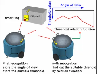
To solve some problems of tag-based object recognition and increase the possibility of the above, we proposed another method for realization of tag-based object recognition which is both easier and simpler to implement by using a smart tag with an active landmark and stereo vision on a pan-tilt mechanism. In previous research, we got high reliability in recognizing or finding an object. But we had a problem that we could not find suitable threshold of an object image for extract feature of an object. So we could not trust an object pose. In this paper, we propose the method to find suitable threshold of an object image by using smart tag. In previous research that decides the threshold of an image, there are two parts of color image and gray image. However the gray image is generally used for a system setup of cheap charge. There are two kinds in the methods of deciding the threshold, the one is the local thresholding method that divide the entire image and decide the threshold in each section.
Fig. 1 Concept of our approach
A threshold decision of the object image by using the smart tag
Chang-Jun Im, Jin-Young Kim, Kwan Young Joung, Ho-Gil Lee Sensing & Perception Research Group Korea Institute of Industrial Technology
( Tel : +82-41-589-8438 )
( E-mail: { catrinne, kjy, j6044, leehg}@kitech.re.kr )
Abstract: We proposed a novel method for object recognition using the Smart tag system in the previous research. We identified
the object easily, but could not assure the object pose, because the threshold problem was not solved. So we propose a new method to solve this threshold problem. This method uses a smart tag to decide the threshold by recording color information of the image when the object feature is extracted. This method records the original of the object color information at the smart tag first. And then it records the object image information, the circumstance image information and the sensors information continuously when the object feature is extracted through the experiments. Finally, it estimates the current threshold by recorded information. This method can be applied the threshold to each objects. And it can solve the difficult threshold decision problem easily. To approve the possibility of our method, we implemented our approach by using easy and simple techniques as possible.
Fig. 2 Smart-tag prototype
Another method is the global thresholding method that decides the threshold in entire one image. The global thresholding method has P-tile method, mode method, repetition threshold selection method and etc. but it is not suitable when the illumination of image is not uniform. Against this, the local thresholding method can overcome the ununiform illumination of image. But the threshold must be selected in each divided section therefore the problem of the global thresholding method exists still. The local thresholding method has adaptation threshold selection method, active threshold method, adaptation multi threshold method and etc.
The previous methods have much possibility that can be decided not suitable threshold value for noise of background image according to decide the threshold value in the entire area of image. More calculating time may be needed and reliability is ambiguous because scan the entire image.
In this paper we propose the method that decides the threshold value of the object image more absolutely in the indoor environments when the robot recognizes the object. This method is as follows. When the robot recognizes the object pose, it adjusts the threshold value and finds out the threshold value which the recognized pose probability is maximum value then saves the threshold value, view angle of the robot and position of the object to smart-tag. When the robot recognizes in next time, it estimates the suitable threshold value by using the object information from the smart-tag. The smart tag is shown in fig. 2. When the robot recognizes the object pose at first, much time is required but as repeats the above process, the processing time is shorter than the first time because many information is stacked in the smart-tag. This method has a fault which the processing time takes long in the first time but it has an advantage which as repeat the processing time, it is reduced. Also the other robot can use the information because the information is stored to the smart-tag of object. In this research, we adopt the method which the robot stores the angle of view and suitable threshold to the smart-tag and estimates the correlation from the information of the smart-tag. This is the reason why we want the results of recognizing to be different as ability of the robot because correlation controls recognizing ability of the robot. That is to say, the smart robot will be had more capability than general robot even if they use same information. The fig. 1
shows the concept of our approach.
2. STATEMENTS OF PROBLEM
The process of image interpretation can be divided as three parts, the first is low level process, the second is middle level process and the third is high level process [10]. The low level process handles the function which is not necessary the intelligence in the process of image interpretation parts. The middle level process handles the function which extracts the feature from the low level processed result image. At this time, the extracting of the feature from the image belongs to the middle level process. The high level process is related to the recognition and the interpretation. And these two processes mean the intelligence recognition. According to result of the middle level process, the reliability of the recognition and interpretation is decided. So the middle level process is very important. The middle level process mainly extracts the feature or make feature of image; the feature is extracting the edge of image. The methods which extract the edge are Laplacian of Gaussian [10], Sobel Edge Detector [10], Canny Edge Detector [10], Prewitt edge detector [10] and etc. but in this paper we used the most famous "Canny Edge Detection" algorithm to extract the edge of an image. The Canny operator was designed to be an optimal edge detector. It takes as input a gray scale image, and produces as output an image showing the positions of tracked intensity discontinuities.
The Canny operator works in a multi-stage process. First of all the image is smoothed by Gaussian convolution. Then a simple 2-D first derivative operator is applied to the smoothed image to highlight regions of the image with high first spatial derivatives. Edges give rise to ridges in the gradient magnitude image. The algorithm then tracks along the top of these ridges and sets to zero all pixels that are not actually on the ridge top so as to give a thin line in the output, a process known as non-maximal suppression. The tracking process exhibits hysteresis controlled by two threshold: T1 and T2, with T1 > T2. Tracking can only begin at a point on a ridge higher than T1. Tracking then continues in both directions out from that point until the height of the ridge falls below T2. This hysteresis helps to ensure that noisy edges are not broken up into multiple edge fragments. Although the same object, the edge information may be different according to the background image. At this time if adjusts the T1 and T2 then we can get the clear information of the object image shown as Fig. 3.
The Fig. 3 is the result which extracts the edge of the image by using canny edge detector and set the threshold value to 200 (T1: 200, T2: 100). The original image is the image which a cup is on a desk. We can not distinguish the cup and desk because the image is very complicate. But if we adjust the threshold value to 100 (T1: 100, T2: 50), we can distinguish the image easily. This is applied to the robot vision. That is to say, if we adjust the threshold value, we can acquire the effective image information. This means that we cannot acquire the information of the variety image at fixed one threshold value.
3. A THRESOLD DECISION OF THE OBJECT
IMAGE
We set two assumptions for this research. The first assumption is that if an object and a background of an image are fixed, the most suitable threshold value will not be changed. The second assumption, if we change the view angle of the camera to the object, the most suitable threshold value will be changed little by little. It can be represented follow equation (1).
(
)
threshold angle of view threshold value threshold value
f
θ
+
+
θ
=
t
+
+
t
(1) If this assumptions are true, we can make the threshold value function by using the most suitable threshold value, view angle of the camera and distance between an object and a robot. This means that the robot uses the most suitable threshold value, therefore it can recognize more reliably. We did experiments to prove our assumptions. We set the threshold value to follow equation (2)
1
2
2
Threshold
=
T
= ⋅
T
(2)We had experiment by using in this method which finds out the most suitable threshold value as change the angle of view.
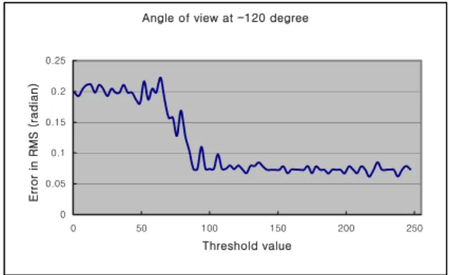
Angle of view at -120 degree
0 0.05 0.1 0.15 0.2 0.25 0 50 100 150 200 250 Threshold value Error in R M S ( radian )
Fig. 4 Correlation graph of threshold and error at -120 degree.
Angle of view at -115 0 0.05 0.1 0.15 0.2 0.25 0 50 100 150 200 250 Threshold value Error in RM S ( radian )
Fig. 5 Correlation graph of threshold and error at -55 degree.
Angle of view at -55 degree
0 0.05 0.1 0.15 0.2 0.25 0 50 100 150 200 250 Threshold value Error in RM S ( radian )
Fig. 6 Correlation graph of threshold and error at -55 degree.
Fig. 7 Object and background image at -120 degree.
Fig. 9 Object and background image at -55 degree. We assumed that illumination of light and movement of object are not changed. The experiment environment is shown at table 1. We assumed that already known the pose of object and then we compared known pose with estimated pose as change the angle of view. Fig. 7, 8, 9 shows the changing angle of view.
Table 1 Experiment condition.
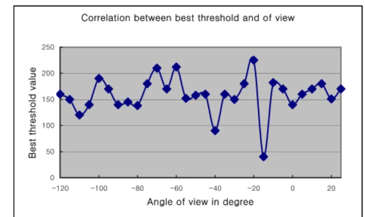
The suitable threshold value is equal to the threshold when minimum error is occurred. We could find out most suitable threshold value while we change a background image little by little as shown the Fig. 4, 7 or Fig. 5, 8 and it shows the correlation between the suitable threshold value and an error value. In this result, we known that if bright of image and bright of background is similar, the error is changed rapidly as change the threshold value (refer Fig. 4, 7 or Fig. 5, 8) but if not, the error is smooth as change the threshold value (refer Fig. 6, 9). We could know that the suitable threshold value is moved to right or left side smoothly as change the angle of view. Therefore we could prove our consumptions. This means that if we have some information about the threshold and angle of view, we will estimate the correlation between angle of view and most suitable threshold value. But we could not find a general equation about correlation because continuous area is very narrow, but we can use it. The Fig. 10 is graphical representation which means the correlation between angle of view and best threshold value at 70cm distance from the object. As you can see, the result of experiment is some different of our expectation. For example, the best threshold is not continued at -15 degree. We investigated about above result, it is discovered that the fluorescent lighting was off at that time.
Correlation between best threshold and of view
0 50 100 150 200 250 -120 -100 -80 -60 -40 -20 0 20
Angle of view in degree
Best thr
es
hold valu
e
Fig. 10 Correlation between best threshold and angle of view.
4. EXPERIMENT AND RESULT
We had known a fact through above section that the correlation between angle of view and best threshold value is equal to equation (1). If the best threshold at 0 degree is 120 and error is 0.5, we can estimate the best threshold at 10 degree. This can be represented as follow equation (3). Satisfying this equation, ‘t + x’ (minimum x) is the best threshold at 10 degree. If satisfying this equation ‘x’ is not exists, the initial threshold is the best threshold.
(
) '
0,
(
)
error errorf
t
+
x
=
f
t
+
x
<
e
(3) : {0, 1, -1, 2, -2, 3, -3...} : error function t: initial threshold x: x<255t+x: the best threshold e: initial error
error x
f
In above case, set ‘t’ to 120, set ‘e’ to 0.5 and then the robot calculate
f
error()
like Fig. 4, 5, 6.
As this result, we had a experiment which is applied to the mobile robot as shows Fig. 11.
The experiment condition is shown at table 2. Table 2 Experiment condition.
We calculate the best threshold at 0 degree, and estimate every best threshold at other degree (10°, 20°, 30°…). The result is shown in Fig. 12.
Comparing graph measured data with estimated data
0 0.1 0.2 0.3 0.4 0.5 0.6 -60 -40 -20 0 20 40 60
Angle of view in degree
Er ro r in RM S ( r adian ) Measured data Estimated data
Fig. 12 The result of experiment
We could find out our estimated data is reliable in the local area (from -30 to 30 degree), but the other area is unreliable. We think the reason is resolution of angle, it is too wide, if the resolution of angle is narrow than 10 degree, the result will be more reliable data.
5. CONCLUSION
In this paper, we proposed the method which decides the suitable threshold to extract edge information of the object image in the object pose recognition. We proved efficiency of our method by attaching the smart-tag which is stored the information for object recognition. Although we did not consider illumination of light, polymorphism of object and evaluation method of pose, we confirmed the result that increased the object pose recognition performance as increasing recognition by storing environment and object information. We could predict the result that if more information is stored, the recognition performance will be better. In next study, we will systematically study about the context awareness by using smart tag considering the illumination of light, the polymorphism of object and the evaluation method of pose.
REFERENCES
[1] D. G. Lowe, "Object recognition from local scale invariant feature", proc of the International Conference
on Computer Vision, Corfu, 1999.
[2] K. Mikolajczyk, C. Schmid, "Indexing based on scale invariant interest points", International Conference on Computer Vision(ICCV), Page(s): 525-531 vol.1, 2001. [3] J. Sullivan, et al., "Bayesian Object Localization in
Images", International J. Computer Vision(IJCV), 44, 2, 111-135, 2001.
[4] D. Kurabayashi, K. Konishi, H. Asama, “Distributed guidance knowledge management by Intelligent Data Carriers”, International journal of Robotics and Automation, vol. 16, no. 4, pp. 207-216, 2001.
[5] D. Kurabayashi, K. Konishi, H. Asama, “Autonomous knowledge acquisition and revision by intelligent data carriers in a dynamic envirionment”, Journal of Robotics and Mechatronics, vol. 13, no. 2, pp. 154-159, 2001.
[6] M. Boukraa, S.Ando, “Tag-based vision: assisting 3D scene analysis with radio-frequency tags”, ICIP02, pp. 269-272, 2002.
[7] M. Boukraa, S.Ando, “A computer vision system for knowledge-based 3D scene analysis using radio-frequency tags”, C2002 IEEE, pp. 412-418, 2002. [8] N.Y. Chong, H. Hongu, K. Ohba, S. Hirai, and K. Tanie,
“Knowledge distributed robot control framework”, Proc. Int. Conf. on Control, Automation, and Systems, pp. 1071-1076, 2003
[9] K. Takemura, K. Ohara, K. Ohba, N.Y. Chong, S. Hirai, and K. Tanie, “Knowledge distributed robot system – tag-based vision system”, SI2003, pp. 317-318, 2003 [10] Rafaedl C. Gonzalez and Richard E. Woods, Digital
Image Processing, Addison-Wesiley Publishing Company, 1992.
[11] J. Canny, A Computational Approach to Edge Detection, IEEE Transactions on Pattern Analysis and Machine Intelligence, Vol. 8, No. 6, Nov. 1986.