ICCAS2005 June 2-5, KINTEX, Gyeonggi-Do, Korea
Development of Fingertip Tactile Sensor for Detecting Normal Force and Slip
Byungjune Choi∗, Sungchul Kang∗∗, Hyoukryeol Choi∗
∗School of Mechanical Engineering, Sungkyunkwan University, Suwon 440-746, Korea
(Tel: +82-31-290-7449; Fax: +82-31-290-7507; Email:[email protected])
∗∗Intelligent Robotics Research Center, KIST, Seoul, Korea
(Tel: +82-2-958-5589; Email:[email protected])
Abstract: In this paper, we present the finger tip tactile sensor which can detect contact normal force as well as slip. The developed sensor is made of two different materials, such as polyvinylidene fluoride(PVDF) that is known as piezoelectric polymer and pressure variable resistor ink. In order to detect slip to surface of object, a PVDF strip is arranged along the normal direction in the robot finger tip and the thumb tip. The surface electrode of the PVDF strip is fabricated using silk-screening technique with silver paste. Also a thin flexible force sensor is fabricated in the form of a matrix using pressure variable resistor ink in order to sense the static force. The developed tactile sensor is physically flexible and it can be deformed three-dimensionally to any shape so that it can be placed on anywhere on the curved surface. In addition, we developed a tactile sensing system by miniaturizing the charge amplifier, in order to amplify the small signal from the sensor, and the fast signal processing unit. The sensor system is evaluated experimentally and its effectiveness is validated.
Keywords: PVDF, Pressure variable resistor ink, Tactile sensor, Signal processing, Robot hand
1. Introduction
In the future, the robot can be performed various tasks to replace the human to every day life. Especially, when hu-manoid robot comes in contact with environments, it must be consider the safety of contact objects in the first place. Accordingly, the future robots are required capability that grasps an object without damaging and slipping during ma-nipulation to determine the amount of contact force and con-tact shape of object. Therefore, con-tactile sensors are an im-portant class of sensors to measure parameters of a contact interaction between the device and some physical stimuli. Many researches about the tactile sensing have advanced with development of new tactile sensor for a guide that could provide the reliable and precise tactile information. Dario et al. developed ‘Artificial tactile sensing system’ for a robot finger [1]. The tactile sensing system detected the contact force, the vibration and the variation of temperature like mechanoreceptor of human by arranging PVDF films that possess piezoelectricity and pyroelectricity. Howe et al. de-veloped dynamic tactile sensor that could detect slippage by means of change of stresses that are happened by deforma-tion of sensing element when artificial skin contacted to the object [2]. Maeno et al. also detected incipient slip between artificial finger and object by fabricating ‘Artificial finger skin’ using PVDF [3]. The artificial finger skin is designed to have characteristics similar to that of a human finger. The finger skin has ridges on the surface in each of which a pair of PVDF film sheets are embedded. Also, in order to judge occurrence of incipient slip automatically they used multi-layered ANN. Koresar et al. realized tactile sensor of 8 × 8 taxel matrix directly by coupling a piezoelectric PVDF polymer thin film to an electrode matrix fabricated on a silicon integrated circuit [4]. Hosoda et al. developed soft
This work was supported by the Ministry of Information & Communications, Korea, under the Information Technology Research Center (ITRC) Support Program.
finger tip has two layers made of different kinds of silicon rubber basically imitating the human finger [5]. And several strain gauges and PVDF films are randomly distributed in both silicon layers. Kawasaki et al. developed distributed tactile sensor that has grid pattern electrodes [6]. These tactile sensor used conductive ink in which the electric resis-tance changes in proportion to the pressure on the top and bottom of a thin film and realized the stable grasp of ob-ject by arranging detecting points of 859 on the palm, the thumb, and each of the fingers. Shimojo et al. used pres-sure conductive rubber as a prespres-sure-sensitive material [7]. The tactile sensor was adopted by stitching wire electrodes into pressure-conductive rubber. Then, they attached the sensor to a four-finger robot hand and grasped a column, sphere, and so on, and showed the experimental data on the transition of the contact points characterizing the grasping operation. However, in its present state, it is difficult to ap-ply tactile sensors to robot hand directly with respect to the problems such as size of external hardware of sensor, devel-opment of algorithm for signal processing and so on. There-fore, a fragmentary detection ability only applied to robot yet. Also, although robot hand attached tactile sensors is used by researcher, it is difficult to grasp object actively and autonomously and to put to practical use because of some problems such as the reliability, accuracy, response speed, dynamic · static characteristic, economical efficiency. In this paper, we propose a miniaturized tactile sensing sys-tem that is possible not only to apply to real robot hand and finger but also to provide information for robot hand to grasp object accurately and safely. To realize this, the PVDF tactile sensor could detect information of slippage such as stick-slip for stabile grasping is developed by mea-suring dynamic response between sensing elements and con-tact surfaces using PVDF. Also, thin flexible force sensor that has a number of sensing elements can recognize shape information of contact object and contact force is developed
by measuring static force by using pressure variable resistor ink. All of sensing system is able to embed by integrating sensor modules and miniaturized signal processing module into robot finger tip. The proposed system is able to com-municate with PC or external devices and the acquired data can be provide information for control of robot finger. This paper is organized as follows. In the next section 2, we introduce the basic principle of PVDF and pressure variable resistor ink. The issues on the development of the PVDF texture sensor and thin flexible force sensor is discussed in the section 3. In the section 4 and 5, the miniaturized signal processing unit is described and experimental procedures for evaluation of the performance of the sensor are mentioned. And finally the paper is concluded with summary in the sec-tion 6.
Fig. 1. Tactile sensing system.
2. Principle of sensing materials
2.1. Principle of PVDF
After Kawai discovered strong piezoelectricity in PVDF (polyvinylidene fluoride) in 1969, PVDF has been used in a lot of commercial products [10]. PVDF is a semicrys-talline polymer with an approximate degree of crystallinity of 50%. The chemical structure of it contains the repeat unit of doubly fluorinated ethene CF2-CH2. The voltage output of
PVDF is 10 times higher than piezo ceramics for the same force input. The reason for the strong piezoelectric activ-ity is related to the large electronegativactiv-ity of fluoride atoms in comparison to the carbon atoms, thus accommodating a large dipole moment.
1
-1
2
-2
3
-3
(Thickness)
(Width)
(Length)
PVDF strip
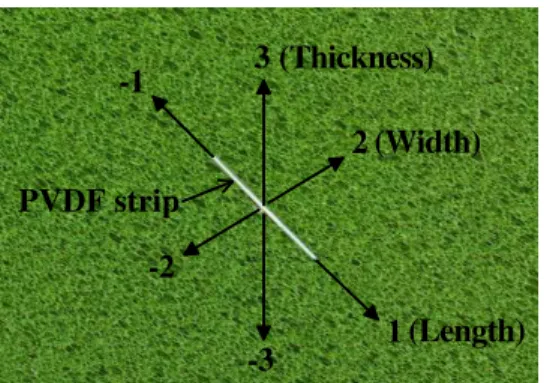
Fig. 2. Reference axes in PVDF strip
The piezoelectric coefficient of PVDF is shown as
dij= 0 0 0 0 d15 0 0 0 0 d24 0 0 d31 d32 d33 0 0 0 (1)
As shown in Fig. 2 the axes are defined in terms of the length direction (direction 1), normal to the length direction in the plane of the film (direction 2) and normal to the plane of the strip (direction 3).
The surface charge Q from the piezoelectric phenomena is proportional to the applied force F via an relation such as
D = Q
A = d3nσn (2)
where D is the charge density, A is the electrode area of the PVDF strip formed in the 3-3 plan, d3nis piezoelectric strain
coefficient for the axis of applied tensile force or compressive force, σ3n is stress applied in the relevant direction. The
d3npiezoelectric strain coefficient is commonly expressed in
[C/mN/m22].
When a PVDF strip is compressed by a probe on a rigid flat surface, assuming, that both the flat surface and the probe are friction-free, the film is free to expand in the 1-1 and 2-2 directions, the output charge can be expressed in Eqs. (4)
Q A = d33σ3= d33( F A3 ) (3) Q = d33F (4)
where d33 is the piezoelectric strain coefficient in the 3-3
direction.
Normally, the output charge is due to a combination of d31,
d32, d33. It is important to remember that, for a given
ap-plied force, the output charge from the PVDF in the length or width direction much higher than that of thickness di-rection [11]. This is because of the extreme thinness of the PVDF film. Therefore, we can develop the miniaturized high sensitivity PVDF sensor using this principles.
2.2. Principle of pressure variable resistor ink The piezoelectric method is not suited for static measure-ments because of the leakage current. If a constant load is ap-plied to a piezoelectric sensor for an extended period of time, the response decreases and eventually becomes zero. Con-sequently, PVDF is suitable for dynamic force sensor better than static force sensor. In this research, pressure variable resistor ink (the product of Creative Materials incorporated) is used to develop distributed force sensor. Pressure variable resistor ink is an electrically conductive ink that decreases in resistance as pressure is increased. It can be blended with other conductive ink to alter the initial and final resistance of the material. Pressure variable ink is blended at a fixed rate is applied between two polyester films which a silver elec-trode is formed using silk-screening technique and sensing element finally is formed.
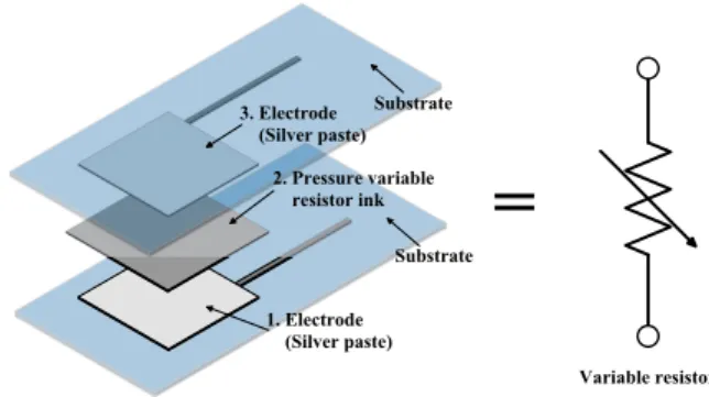
As shown in Fig. 3 force sensor is fabricated through in-sertion of ink between two polyester film that has electrode pattern. Each of polyester film and electrode is physically
flexible. The fabricated force sensor is possessed single sens-ing element and it can be modelled as a variable resistance that decreases in resistance as pressure is increased such as Fig. 3.
=
V a r i a b l e r e s i s t o r S u b s t r a t e S u b s t r a t e 3 . E l e c t r o d e ( S i l v e r p a s t e ) 2 . P r e s s u r e v a r i a b l e r e s i s t o r i n k 1 . E l e c t r o d e ( S i l v e r p a s t e )Fig. 3. Structure of force sensor that has one sensing element
The Fig. 4 explains the operational principle of fabricated force sensor. When the fixed input voltage is applied to sensor, force sensor can obtain a variation of output value that is amplified by voltage gain. The output equation from explained inverting amplifier is expressed in Eqs. (5)
Vout= −Vcc
RF
Rs
= −VccRFSs (5)
where Rsis resistance of force sensor, Ssis conductance that
is defined as the reciprocal of resistance. Also, RF is the
op-amp’s feedback resistance.
- V c c V o u t S e n s o r R F R S + -F o r c e s e n s o r ( S i n g l e s e n s i n g e l e m e n t )
Fig. 4. Basic principle of operation of force sensor
3. Design of finger tip tactile sensor
3.1. PVDF texture sensor
In this chapter, we propose the miniaturized high sensitiv-ity PVDF sensor which is attached to robot finger. Af-ter Polyvinylidene fluoride pellets of Aldrich Chemical Co., Inc. were arranged between polyimide films, these pellets are pressed at 230◦C ∼ 240◦C for 25 minutes with an applied
pressure of 10MPa using hot press machine. Then, PVDF film allowed to cool to room temperature about 1◦C/sec.
The thickness of fabricated films has a value between 50µm and 70µm. Then, the surface electrodes, which are both sides, are fabricated using silk-screening technique with sil-ver paste. By this method, the fabrication process was be-came more simple and fabrication cost was decreased. The thickness of silver electrode is 5µm, and it can stand heat of 200◦C. In order to exhibit high piezoelectricity in the
fabri-cated films, we polarized the fabrifabri-cated PVDF film by ap-plying the strong electric field using the high voltage supply after the electrodes of copper were attached on either side of the film. Poling was carried out at 170◦C with an applied
voltage of 3kV and load of 5N. With the voltage applied, the film was placed on a glass substrate with mechanical con-strain and held at 170◦C for 30 h, then allowed to cool to
coolant before the applied voltage was removed. The PVDF films were polarized is characterized by piezoelectricity. As shown in Fig. 5, PVDF sensor has single PVDF sensing element, and used film of 100µm thickness to increase the sensitivity. PVDF strip, width 0.8mm and length 10.0mm, has sensing element of 0.4mm × 4mm size.
0 . 1 m m 1 0 m m
0 . 8 m m
P V D F s t r i p E l e c t r o d e
Fig. 5. Schematic of PVDF sensor and photograph
3.2. Thin flexible force sensor
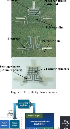
According as the sensing elements become much increased, the sensor needs many wirings. Also, if we want to receive from a large number of sensing elements independently, de-sign of sensor becomes complicated and size of each detection element is decrescent because of wiring. Moreover, a num-ber of input and output ports required microcontroller to process data, and the load of hardware becomes more in-creased. To develop force sensor of high resolution from the above mentioned requirements, matrix method of grid type is used in this research. The two polyester films were ori-ented together so that their traces formed a grid, with the pressure variable resistor ink layers facing each other. Each cross section of the grid formed a sensing element of force sensor. As shown in Fig. 6 and Fig. 7, the size of sens-ing element is 0.5mm × 0.5mm and a force sensor has total 24 sensing elements. If tactile sensors independently receive the output signal from the each of sensing element, totally 48 signal line is required and serious problem will be cause in the limited space. However, as matrix method of grid type was applied in the force sensor, it is possible to detect 24 sensing elements only 8 input voltage lines and 4 output
signal lines. Hence, it provides to simplify spatial resolution and integration of operation circuit.
E l e c t r o d e P r e s s u r e v a r i a b l e r e s i s t o r i n k P o l y e s t e r f i l m P o l y e s t e r f i l m E l e c t r o d e S e n s i n g e l e m e n t ( 0 . 5 m m x 0 . 5 m m ) 2 4 s e n s i n g e l e m e n t s
Fig. 6. Finger tip force sensor
4. Fabrication of tactile sensing system
In this chapter, we introduce the miniaturized tactile sens-ing system to process data is transmitted from a number of sensing elements. After signals is measured from the sens-ing elements of tactile sensor is amplified and is transformed into digital data in the A/D converter that is included in the microcontroller, the data is collected is transmitted user interface on PC by an RS232 serial communication or input port of an external device(Fig. 8).
4.1. Amplifiers
The amplifier is consists of two types, PVDF sensor ampli-fier and force sensor operation ampliampli-fier. Because the output of PVDF depends on an instant variation, it is electrically charged for a relatively short time. Therefore PVDF tactile sensor is responsive only to a changing stress rather than to a steady level of it. Considered these problems, we designed PVDF sensor amplifier. PVDF sensor amplifier basically is used to convert to voltage signals from the PVDF strip which generate very low charges. The size of developed PVDF sen-sor amplifier is 18mm × 14mm and it has input and output port of 2-channel respectively. The circuit of PVDF sensor amplifier is consists of Charge amplifier, non-inverting am-plifier and 60 Hz notch filter.
E l e c t r o d e P r e s s u r e v a r i a b l e r e s i s t o r i n k P o l y e s t e r f i l m P o l y e s t e r f i l m E l e c t r o d e S e n s i n g e l e m e n t ( 0 . 5 m m x 0 . 5 m m ) 2 4 s e n s i n g e l e m e n t s
Fig. 7. Thumb tip force sensor
Fig. 8. Schematic of tactile sensing system
Unlike PVDF sensor amplifier, force sensor amplifier is em-ployed to operate force sensor because it sends output volt-age by variation of voltvolt-age gain with amplifier. The force sensor amplifier is shown in Fig. 9. It has input, output port of 4-channels and is miniaturized to embed finger tip and thumb tip of robot hand.
4.2. Signal processing board
The circuit was designed on the single board for data acqui-sition, control, communication. Data acquisition and com-munication is performed by using microcontroller(Silicone laboratory, C8051F311), signal processing board is able to transmit data to user interface on PC by an RS232 serial communication or input port of an external device by SM-Bus.
Thin flexible force sensor is fabricated by using matrix method of grid type. The microprocessor can receive out-put signal from a number of sensing elements by scanning to acquire the measured data at regular time interval. There-fore, 8 digital output ports of signal processing board become input voltage of force sensor, 4 A/D convert ports is received
D a t a a c q u i s i t i o n b o a r d
B y p a s s f i l t e r
A m p l i f i e r f o r f o r c e s e n s o r
A m p l i f i e r f o r P V D F s e n s o r
Fig. 9. Photograph of tactile sensing system
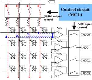
output signal of force sensor. Also, 2 A/D converter ports of signal processing board is received the amplified output signal of PVDF sensor. The scanning circuit of force sensor is shown in Fig. 10. The part which variable resistor and capacitor is connected in parallel is sensing element. The dig-ital output lines of microcontroller serially is changed “High” and a microcontroller is received the output signals of sens-ing elements by operatsens-ing AD converter. Therefore, matrix method effectively is able to control the number of sensing elements by using minimum input voltage and output signal line. A D C 0 A D C 1 A D C 2 A D C 3 + + + + -C o n t r o l c i r c u i t ( M C U ) D i g i t a l o u t p u t c o n t r o l A D C i n p u t c o n t r o l
Fig. 10. Thin flexible force sensor scanning circuit
The sensing data that is acquired from the microcontroller provide three-dimensional data to user through user inter-face on PC or is able to supply measured information with external device for precise control and operation.
5. Experiment
PVDF sensor was miniaturized to attach finger tip and thumb tip of robot hand. The graph of Fig. 11 shows the characteristic of response when the PVDF sensor was touched and rubbed by object or finger tip. Fig. 11 shows
sudden change of gradient. It means that stick-slip occurred between the sensor and contact surface. Fig. 12 shows the characteristic of response when the weight of 100g rolled on the sensing element of PVDF sensor. Unlike Fig. 11 an effect of stick-slip seldom or never exists. So, a change of gradient is slow and when the weight of 100g rolls on the sensing element indicates about 1.2V constant value. There-fore, according to surface characteristic of contacted object and contact method, we are able to confirm that the charac-teristic of response is different.
Furthermore, thin flexible force sensor of matrix array is fab-ricated to attach finger tip and thumb tip of robot hand. Fig. 13 shows characteristic of response from the fabricated force sensor. When we applied to the weight of 100g and 200g, the output voltage of 2V and 4.25V was obtained respectively. As shown in graphs, the sensing element of force sensor in-dicate the output voltage without delay. The noise occured on the graph is contact noise and it could be conspicuously decreased by using developed bypass filter.
Fig. 11. When the PVDF sensor was touched and rubbed by object or finger tip.
Fig. 12. When the weight of 100g rolled on the sensing element of PVDF sensor
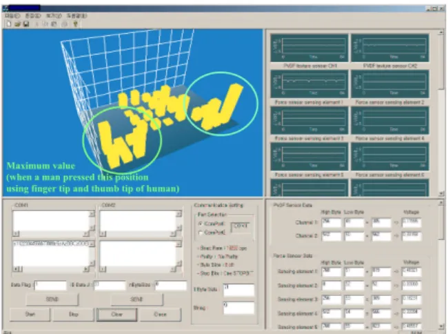
Finally, PVDF sensor and force sensor was attached the de-veloped sensing system. Then, we confirmed contact infor-mation through user interface on PC. Fig 14 shows the con-tact information when we pressed sensors in finger tip and thumb tip of human. The finger tip and thumb tip is situ-ated the indicsitu-ated areas and the maximum value displays in this area. Therefore, we could confirm that the developed force sensor enables a measurement of static force as well as local force detection through experiments. Also, the varia-tion of dynamic force applied in this sensing elements can detect using PVDF sensor.
W h e n w e a p p l i e d t o t h e w e i g h t o f 1 0 0 g W h e n w e a p p l i e d t o t h e w e i g h t o f 2 0 0 g O u t p u t v o l t a g e : a b o u t 2 . 0 0 V O u t p u t v o l t a g e : a b o u t 4 . 2 5 V
Fig. 13. When we applied to the weight of 100g and 200g.
M a x i m u m v a l u e
( w h e n a m a n p r e s s e d t h i s p o s i t i o n u s i n g f i n g e r t i p a n d t h u m b t i p o f h u m a n )
Fig. 14. When we pressed sensors in finger tip and thumb tip of human.
6. Conclusion
In this research, a tactile sensor which can detects contact normal forces as well as slip was developed. The developed sensor is made of two different materials, such as polyvinyli-dene fluoride (PVDF) that is known as piezoelectric poly-mer, and pressure variable resistor ink. In order to detect slip between sensor and object, a PVDF strip is arranged along the normal direction. Also, a thin flexible force sensor is fabricated in the form of a matrix using pressure variable resistor ink in order to sense the static force. The matrix method effectively enabled to control the number of sensing elements by using minimum input voltage and output signal line. Also, the developed sensing system was miniaturized to integrate system into robot finger. The developed tactile sensor is physically flexible and it can be deformed three-dimensionally to any shape so that it can be placed on any-where on the curved surface. The sensing data that was ac-quired from the microcontroller provided three-dimensional data to user through user interface on PC or was able to supply measured information with external device for pre-cise control and operation. In the future, we will couple up the tactile sensing system to the robot hand to evaluate the effectiveness of this tactile sensing system.
References
[1] P. Dario and G. Buttazzo, “An Anthropomorphic Robot Finger for Investing Artificial Tactile Perception”, Int.
J. Robotics. Res., vol. 6, no. 3, pp. 25-48, 1987. [2] R. D. Howe and M. R. Cutkosky,“Dynamic Tactile
Sens-ing: Oerception of Fine Surface Features with Stress Rate Sensing”, IEEE Transaction on Robotics and Au-tomation, vol. 9, no. 2, pp. 140-151, 1993.
[3] I. Fusjimoto, Y. Yamada, T. Maeno, “Development of Artificial Finger Skin to Detect Incipient Slip for Re-alization of Static Friction Sensation”, Proc. of IEEE Int. Conf. on Multisensor Fusion and Integration for Intelligent Systems, MFI2003, pp. 15-20, 1999. [4] E. S. Kolesar, C. S. Dyson, R. R. Reston, R. C. Fitch,
D. G. Ford and S. D. Nelms, “Tactile Integrated Cir-cuit Sensor Realized with a Piezoelecric Polymer”, In-novative Systems in Silicon, Proceedings., Eighth An-nual IEEE International Conference on, pp. 372-381, 1996.
[5] Y. Tada, K. Hosoda, Y. Yamasaki, M. Asada, “Sens-ing the Texture of Surfaces by Anthropomorphic Soft Fingertips with Multi-modal Sensors”, Proc. IEEE/RSJ Int. Conf. on Intelligent Robots and Systems, vol. 1, pp. 31-35, 2003.
[6] H. Kawasaki, T. Komatsu, K. Uchiyama, “Dexterous Anthropomorphic Robot Hand with Distributed Tactile Sensor: Gifu hand II”, IEEE/ASME Transactions on Mechatronics, vol. 7, issue. 3, pp. 296-303, 2002. [7] M. Shimojo, A Namiki, M. Ishikawa, R. Makino,
and K. Mabuchi, “A Tactile Sensor Sheet using Pres-sure Conductive Rubber with Electrical-Wires Stitched Method”, IEEE Sensors Journal, vol. 4, no. 5, pp. 589-596, 2004.
[8] H. R. Nicholls and M. H. Lee, “A survey of robot tactile sensing technology”, Int. J. Robot. Res., vol. 8, no. 3, pp. 3-30, 1989.
[9] M. H. Lee and H. R. Nicholls, “Tactile sensing for mechatronics-A state of the art survey”, Mechatronics, vol. 9, pp. 1-31, 1999.
[10] H. Kawai, “The Piezoelectricity of Poly(vinylidene flu-oride)”, Jpn. J. App1. Phys., vol. 8, pp. 975-976, 1969. [11] J. Dargahi, “A piezoelectric tactile sensor with three sensing elements for robotic, endoscopic and prosthetic applications”, Sensors and Actuators A: Physical, vol. 80, pp. 23-30, 2000.
[12] R. A. Russell, “Robotic Tactile Sensing”, Prentice Hall, Inc, 1990.
[13] J. Fraden, “Handbook of Modern Sensors: Physics, De-signs, and Applications”, American Institute of Physics Press, 1997.
[14] J. Butterfass, M. Grebenstein, H. Liu, G. Hirzinger “DLR-Hand II: Next Generation of a Dexterous Robot Hand”, Proc. of IEEE Int. Conf. on Robotics and Au-tomation, vol. 1, pp. 109-114, 2001.
[15] C. M. A. Ashruf, “Thin flexible pressure sensor”, Sen-sors Review, vol. 22, no. 4, pp. 322-327, 2002.
[16] K. H. Yu, T. G. Kwon, M. J. Yoon, S. C. Lee, “Develop-ment of a Tactile Sensor Array with Flexible Structure using Piezoelectric Film”, KSME International Journal, vol. 16, no. 10, pp. 1222-1228, 2002.