ICCAS2005 June 2-5, KINTEX, Gyeonggi-Do, Korea
Development of a Simplified Eddy Current Tester Specialized in Non-Iron Metals
XiaoDong Zhang*, Muneyoshi Tamura*, Tomoo Aoyama*, Umpei Nagashima**
* Faculty of Engineering, University of Miyazaki, Miyazaki 889-2192, Japan(Tel: +81-985-58-7411, E-mail: [email protected]) ** National Institute of Advanced Industrial Science and Technology, Japan
Abstract: We constructed an eddy current tester as education programs of electronics and computers. The tester is designed based on frequency counting of square-waves digitally, where information of phase is lost, but which is very compact. Main controller of the tester is PIC16HC84A. Other parts, detection-coils, oscillators, and stabilizers are made by us. The tester is able to detect change of order(-5) in waves of 1MHz, whose function is kept in several minutes. The measurement period is 10-20 msec in the several minutes. Using the tester, we observed narrow gaps of copper/aluminum wires, and detected resistivity difference of 1.7 or 2.7 [10-8
ohm*m].
Keywords: eddy current testing, non-invasive measuring, education program
1. INTRODUCTION
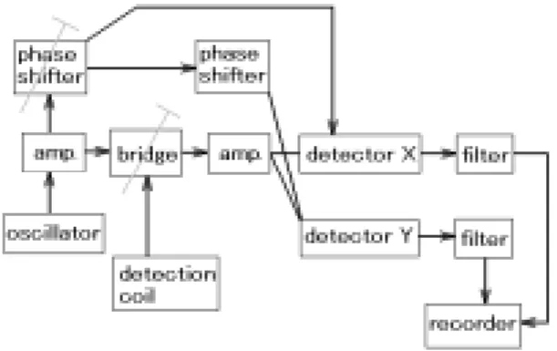
Eddy current testing is an effective non-invasive measuring, and it is used for many kinds of conductors’ properties. It is able to real-time observations at dangerous places. We interest in the eddy current testers; however, it is expensive because of complex structures [1] that are shown in Fig.1.
Fig. 1 Block diagram of an eddy current tester. In the tester, sine-wave alternative currents are used. T-mark is to require adjustment.
We wish to redesign the block diagram, and to develop a simplified tester. In commercial eddy current testers, electric analogue signals are used, and the impedance of detectors are observed strictly. However, it is difficult to develop a simplified tester on the design. Our objective is to find another design, and to confirm it.
The first key point of reduction is to abandon impedance measurements, and to find a substitution on digital signals. The second is to adopt a micro processor as a controller of the tester. It is to make the control scheme be programmable. The micro processor has an accumulator usually, which is used to count up digital pulses. The function is enable in MHz-field, which is very useful. Sine waves are used in orthodox eddy current
testers, but we adopt square waves. We count up frequency pulses of eddy-current-detector instead of analogue impedance-measurement. The approach has defect points, where the most one is to lose phase-information.
Eddy current detection has non-linear responses. It is inappropriate for testers. However, we have neural network technologies, and we can correct non-linear observations, c.f. [2]. Thus, it is not fatal problem as for non-linear responsiblity of eddy-current testing. We believed that omissions of phase-demodulater and LC-oscillator-stabilizers were more important points. The original idea was designed by researchers in Tokyo-Gas Co. Ltd. [3]. One application was reported in FA03-1 of ICCAS’04 [4]. In this report, we make high-precision of the tester, and detect properties of non-iron metals.
2. REENGINEERING OF EDDY CURRENT
TESTER
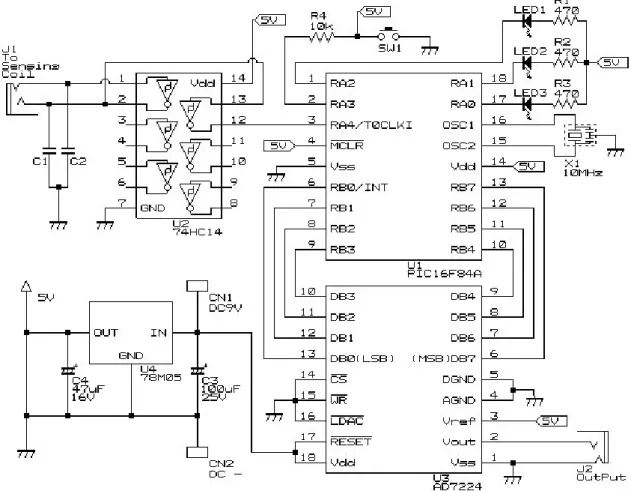
We construct of a Colpitts-oscillator by using a coil, capacitor, and Schmitt-triger-inverter 74HC14, which are shown in Fig. 2. The oscillator gives square-waves that is countable. We use 8-bit wraparound counter TMR0 in micro-CPU, PIC16F84A. Then, we can get frequency of waves accurately.
Fig.2 Colpitts-oscillator.
74HC14 has 6 Schmitt-triger-inverters. C is poly-ester film capacitor.
ICCAS2005 June 2-5, KINTEX, Gyeonggi-Do, Korea The coil is handmade on a soda-glass-tube 6mm in diameter.
The tube is hollow, and the thickness is 1mm. The thickness of Cu-wire insulated by poly-uretane is 0.33mm. We made two coils, where the width of rolled wire was 5 or 10mm. Inductances of those coils are in Table 1. These coils are operated as inducters between 100kHz-1.2MHz.
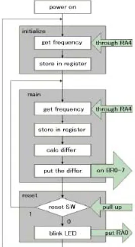
RA4-pin, and mode of PIC is PA4-output. This is a kind of wired-AND. Thus, we generated gate-terms of 10-20 msec.
Table 1 Characters of emittion/detection coils. Where C1 and C2 are poly-ester film capacitors.
width C1=C2 observed fq. inductance 10 mm 0.1 [micro-F] 0.01 0.0047 0.0022 0.001 115.8 kHz 368.5 539.6 799.5 1163 0.0378 mH 0.0373 0.0370 0.0360 0.0375 5.0mm 0.1 [micro-F] 0.01 0.0047 0.0022 0.001 117.3 kHz 376.6 556.0 824.2 1207 0.0368 mH 0.0357 0.0349 0.0339 0.0348
The coil emits magnetic field, and also a detector of eddy currents in samples. The currents give impedance-change of the coil, and the change makes frequency-shift of the oscillator. The shift order is 5.0-200Hz, which is got as the difference of frequency-counters. The value indicates properties of samples. Since the shift is very small, we adopt inner counter in PIC. The bit-numbers is 8, so, absolute frequency is not counted. Colpitts-oscillator is not so stable as temperature-changes. To escape the unstability, we set counting-start-frequency to a register in the PIC. The stored value is modulus of true frequency. The setting is repeated over every several minutes, and a period between settings is used to get difference-
Fig.3 Counting scheme of the difference frequencies.
3. GENERAL OUTPUT INTERFACE
frequencies. It has a function like oscillator-stabilizers. Outline scheme of the tester is shown in Fig.3.
It is not necessary to detect electro-magnetic properties; however, since we are required to attach a general output interface, we design a DA-converter that is converted frequency-differences to output-voltages. We adopt AD7224 as the DA-converter, then, maximum output voltage is 5.0 V, and the decomposition is 8-bits. The DA-converter makes peak-hold function of digital multi-meters possible. It is secondary effect; so, we escape from design of sample moving unit.
Table 2 Pin assignments of PIC16HC84A pin # mnemonic Meaning
1 2 3 4 RA2 RA3 RA4 ~MCLR
confirm the status, for LED reset, pull up
input/output, connected to oscillator (not) reset 5 6-13 14 15-16 Vss RB0-7 Vdd OSC2,1 Ground Data path power supply, 5V input clock 17 18 RA0 RA1
blinking LED when reset not use
Whole block diagram is shown in Fig. 4. An outward form of the tester is 11cm×15cm×6.5cm.
Where, we explain RA4-input/output-pin connected to TMR0 counter in PIC. Counting frequency is to count up number of high-level pulses on the RA4. That is, it is necessary to define the count-up term. We call it gate-(open)-term.
The gate-term is defined, when input signals are put on
ICCAS2005 June 2-5, KINTEX, Gyeonggi-Do, Korea
Fig. 4 Block diagram of eddy current tester.
4. TRIAL RUN OF THE TESTER
4.1 Making of samples
We interested in electro-magnetic properties of non-iron conductors, copper and aluminum. Samples are put in the hollow of an emission/detection coil. Therefore, the sample is small size under diameter of 3.5mm. We observed properties of wires, i.e. Fig.5.
Fig.6 Output voltages of copper wires’ gap (diameter=2.0mm). Where gate-term is 10 msec, width of coil is 5 mm, capacitors are 0.1 micro-Farad (117.3 kHz). We observed 10 times and plotted them. The plotted points are condensed in small area. The unit of vertical axis is [-V] that is differences between measured- and starting-voltages which are converted from frequencies. The horizontal axis is gaps [mm] of wires. Approximate polynomial of the outputs is, y=0.020x2+0.014x Fig.5 Samples.
The material is copper or aluminum. The gap is covered by poly-vinyl tape.
4.2 Detections of gaps of copper/aluminum wires
+0.0042, R2=0.9893. Where, x is gap-length, and y is minus output voltages. The non-linearity of the observations is shown in the coefficient of x2. The value of R2 relates precision of
detections. It is very high. First, we predicted complex non-linearity functions; however, it was not necessary.
We made tests to detect gaps of copper or aluminum wires in diameter 2.0mm. We got following results, which were shown by Fig.6 and Fig.7.
ICCAS2005 June 2-5, KINTEX, Gyeonggi-Do, Korea
Fig.7 Output voltages by gaps of aluminum wires (diameter=2.0mm).
Where gate-term is 10 msec, width of coil is 5 mm, capacitors are 0.1 micro-F (117.3 kHz). We observed 10 times and plotted them, which were found in narrow area. The vertical axis is minus voltages [-V], and the horizontal axis is gaps [mm] of wires. Approximate polynomial of the outputs is, y = 0.0391x2
+ 0.0194x + 0.0207, R2 = 0.9894. In case of aluminum, the non-linearity is larger than that of coppers.
Fig.6/7 are drawn by difference voltages from references that are set at starting of observations. The drawing indicates gaps clearly; however, it doesn’t show difference of the matters. Thus, we redraw Fig.8 based on a common reference.
Fig.8 Absolute output voltages of copper/aluminum. Where gate-term is 10 msec, width of coil is 5 mm, capacitors are 0.1 micro-Farad (117.3 kHz). We observed 10 times and plotted them. The plotted points are condensed in small area. The unit of vertical axis is [+V] that is measured-voltages that are converted from frequencies. The horizontal axis is gaps [mm] of wires. The figure shows that electro-conductivity of copper is higher than aluminum. The diamagnetic effect of copper is very small. The tester distinguishes difference of materials for copper and aluminum.
We observed skin effects of eddy currents on aluminum wires. That is shown in Fig.9.
Fig.9 Skin effects on aluminum wires.
Where gate-term is 10 msec, width of coil is 10 mm, capacitors are 0.1 micro-F (116kHz), 0.022 micro-F (800 kHz). We observed 10 times and plotted them. The plotted points are condensed in small area. The unit of vertical axis is [-V] that is differences between measured- and starting-voltages which are converted from frequencies. The horizontal axis is gaps [mm] of wires. Approximate polynomials of the outputs are;
y = 0.0109x2 + 0.0309x + 0.0037, R2 = 0.9998, for 116kHz,
y = 0.0922x2 + 0.0481x + 0.0427, R2 = 0.9980, for 800kHz. The effect gives eddy-current-testing strong non-linearity; however, in the high-frequency area, eddy current testing is more sensitive.
5. CONCLUSION
We constructed an eddy current tester, in which the design is based on digital counting of square-waves that are influenced by properties of matters. On the design, we lose information of phase, but we can construct testers in small components (We
may design testers of size of a finger). The eddy current tester is
able to detect frequency change of order(-5) in 1MHz, whose function is kept in several minutes. The measurement period is 10-20 msec in the term. Using the tester, we observed narrow gaps of copper/aluminum wires, and did the skin effects. Thus; 1. Resistivity difference between copper and aluminum (Cu=1.7, Al=2.7 [10-8 ohm*m]) is detected,
2. Difference of magnetic susceptibilities isn’t observed (Cu=-5.5, Al=16, [10-6emu/M-1]),
3. Amplitude of eddy currents is represented by second-order polynomials (R2>0.989).
4. By skin effects, we find non-linear coefficient of 8 times at 800 kHz, and get twice amplitude of output-voltage. It makes the tester sensitive.
REFERENCES
[1] Ed. of the Japan society for non-destructive inspection,
Eddy current testing No.3 (in Japanese), publishing in the
society, 2003.
[2] K. Oobayashi, Y. Yuan, T. Aoyama, “Applications of artificial neural networks: Detections of the location of a sound-source”, ICCAS’03, TE06-02, 2003.
[3] Virtual research institute of sensing technologies in Tokyo- Gas, http://www.netdecheck.com/sensing_tech/exp3/01.html. [4] K.Obayashi, M.Tamura, X.Zhang, T.Aoyama, “Noninvasive measuring: Detections of materials and quantities on eddy current testing”, ICCAS’04, FA03-1, 2004.