Chul-Jin Kim, Yu-Seong Yun*
1, Do-Tae Kim and IL-Young Lee
2Department of Mechatronics Engineering, Kyungil University, Daegu 712-702, Korea
1Department of Safety Engineering, Pukyong National University, Busan 608-739, Korea 2Department of Mech & Automotive Engineering, Pukyong National University, Busan 608-739, Korea
(Received June 7, 2012; Accepted November 14, 2012)
Abstract : Recently, the combined power plants are refocused rapidly as a replaceable energy system of the nuclear power plant. The large turbine is revolved highly at 1800~3600 rpm. Thus, the turbine speed should be monitored with mechanical and electrical method for a safety. The electrical cutoff valve which blocks the flow channel with the electrical signal is with a built in. The aim of this study is to develop a manufacturing technology through by the localization of a solenoid actuated directional control valve. Especially the results show performances of the solenoid valve by the experiments and modeling and the reliability estimation. Applied load port pressure was changed rapidly on the form of a quadratic curve over time. And in the cases of square waveform when 0~100 V and 20~120 V input voltage, it was driven on a stable state until 13.4 Hz and 16.6 Hz, respectively. We think that this study will give useful data for the electricity safety system of the combined power plant gas turbine. Key words : diectional control valve, solenoid, spool, overlap, chamber pressure, response time
1. Introduction
Recently, the power plants are refocused rapidly as a replaceable energy system of the nuclear power plant after the nuclear power accident at Hukushima, Japan in 2011. Especially the combined power plant is composed of the gas turbine power and thermal power. It improves the efficiency of the thermal power and uses high tem-perature gas from the gas turbine power. The large tur-bine of the comtur-bined power plant is revolved highly at 1800~3600 rpm. Thus, the turbine speed should be mon-itored with mechanical and electrical method for a safety. The electrical cutoff valve which blocks the flow channel with the electrical signal is with a built in a main valve, pilot valve, relief valve, filter and LVDT. The mechanical and electrical cutoff valves are almost imported. Therefore, the localization of these cutoff valves for a power plant is necessary for the purchase cost and term efficiently Thus, the aim of this study is to develop a manufacturing technology through by the localization of a solenoid actuated directional control
valve. Especially the results show performances of the solenoid valve by the experiments and modeling and the reliability estimation. We think that this study will give useful data for the electricity safety system of the com-bined power plant gas turbine domestically.
2. Driving principle and manufacture of the
solenoid valve for a combined power plant
2.1 Driving principle of the solenoid valve for a com-bined power plant
The solenoid actuated directional control valve for a combined power plants(hereinafter “solenoid valve”) is that the displacement of main spools follows on the dis-placement of the pilot spool. The spool operation types are single coil type(S type) and double coil type(D type). Both types of the solenoid valve are driven by the same principle. Figure 1 shows the driving principle of S type valve by the operation of the solenoid vale from the normal state at the solenoid OFF.
In Figure 1(a), the pilot spool part in the OFF state, the solenoid is not excited, keeps the state of the left in close contact with the spring cap by the spring force.
The same flow area of the spool and the pilot spool and the same left and right pilot chamber pressure make the main spool maintain a stable position. Solenoid as rims Figure 1(b) shows a solenoid in the ON state, when the pilot spool runs to the right, flow channel to the left side of the pilot chamber euro is formed and the left side of the pilot chamber pressure rises to the near sup-ply pressure as the hydraulic pressure supsup-ply. And the right pilot chamber pressure is falling close to the tank pressure as the flow channel is formed from the right pilot chamber pressure to the return side. As a result, the left and right side of the pilot chamber of the pres-sure difference occurs and the main spool is pushed to the right pressure due to the pressure difference. 2.2 The valve block and spool
Figure 2 shows the modeling of a valve block and inner section area configuration. A valve block is the body as core components of the solenoid valve which controls the
hydraulic fluid flow rate and flow direction with the smooth movement of the spool by solenoid force. A small clearance caused by machining error moves the actuator in detail and a valve causing leakage of hydraulic fluid degrade performance, as well as the system to become unstable. Thus, it is important to make optimal machining accuracy and fine materials for the valve block.
Figure 3 shows a modeling of s spool by 3D. A spool is a key element to control the direction of flow of the hydraulic fluid, moving within the valve block. And material selection and machine processing are important factors for the influence of the valve charac-teristics. A spool land in the metering notch or groove shape processing is designed to appear in hydrostatic bearings effects in the most effective way to satisfy these constraints. A dual-pilot spool type was adopted and the surface of the spool was coated by non-electro-lytic nickel plating.
2.3 The solenoid and guide
Figure 4 shows modeling of the solenoid and section configuration. The voltage of the solenoid that is used in a combined power plant in the field is 127 V and the humidity at surrounding is little. The temperature range using the solenoid valve is in the range of 20~60oC by considering the temperature of the interior space where flow of air is little. Solenoid enclosure meets the con-dition of ICS 6 ANSI / NEMA and UL 429/508/1002.
Fig. 1. A driven principle and structure of the valve.
Fig. 2. Modeling of a valve block and inner section area con-figuration.
Fig. 3. 3-dimensional modeling of the spool.
3. The performance test for the solenoid valve
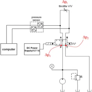
3.1 The performance test for the solenoid valve Figure 5 shows the overview of experimental appara-tus for the solenoid valve performance. Pressure can be measured according to the solenoid activation from port A, port B. Valve performance experiments were con-ducted in the following order:
① 100 bar pressure supply in a locked throttle valve state.
② The pressure of applied load port is measured by the solenoid supply voltage ON / OFF repeatedly (D type solenoid on the left and right cross to work).
③ ② behaviors as throttle valve somewhat open. 3.2 The results of performances test
Figure 6 and 7 show the results of the measurement of the solenoid voltage and pressure characteristics on each port. Applied load port(port A, B) pressure can be characterized according to the valve internal leakage (P → A.B A.B → T) and the time (delay in response time) which is from the applied starting time to the response appearing time.
Figure 8 shows the pressure characteristics of applied load port according to the internal leakage of the valve. While all the flow channel of the valves blocked in the solenoid ON and pressure falling and rising over time on B. co. valve have the gentle slope of the straight line, applied load port pressure is changed rapidly on the form of a quadratic curve over time. We think about the
reason comes from the size difference of the internal leakage pathway between developed valve and B. co. valve due to solenoid ON.
Figure 9 shows pressure response characteristics using the developed solenoid coil. The response time is 0.084 second and 0.083 second on A→ B and B → A
respec-Fig. 5. The overview of experimental apparatus for the sole-noid valve performances.
Fig. 6. The solenoid voltage and pressure characteristics (B. co. valve and new solenoid valve coil).
Fig. 7. The solenoid voltage and pressure characteristics (New solenoid valve and coil).
tively. And relay time was 0.036 and 0.032 seconds. Figure 10 shows the response characteristics for the delay time and response time at the D type solenoid valve. Depending on solenoid ① or ②, the operation of the hydraulic fluid passage is formed as P→ A, B → T or P→ B, A → T. The results can be found from pres-sure meapres-surement of the applied load port.
3.3 Reliability evaluation test
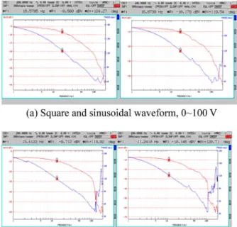
In order to certificate performance of the solenoid valve developed to protect the combined power plant gas when faced with a dangerous situation, the evaluation of the reliability of the solenoid was conducted by KS C 4530 and KS C 4532 reference. In this study, only fre-quency response characteristic is shown due to a lack of pages. The tests are carried out by sine wave and a square wave frequency input from 1 Hz up to 200 Hz. The forces exerted by the frequency converted to
fre-quency characteristics and the input frefre-quency was obtained when dB value of 1 Hz goes down to -3 dB. Figure 11 shows results in the cases of square waveform when 0~100 V and 20~120 V input voltage. It is expect-ed to be driven to a stable state until 13.4 Hz and 16.6 Hz, respectively. In addition, the results seem to be similar when sinusoidal waveform is used. In that case, it was 11.2 Hz and 16.9 Hz for 0~100 V and 20~120 V input voltage. Also it can be driven in a stable.
4. Conclusions
In this work, performance tests of the solenoid valve were implemented by the experiments and the reliability estimation to develop a manufacturing technology through by the localization of a solenoid actuated directional control valve. The results are as follows below.
(1) Applied load port pressure was changed rapidly on the form of a quadratic curve over time, while all the flow channel of the valves blocked in the solenoid ON and pressure falling and rising over time on conventional valve have the gentle slope of the straight line.
(2) The response time is 0.084 second and 0.083 sec-ond on A→ B and B → A respectively. And relay time was 0.036 and 0.032 seconds.
(3) In the cases of square waveform when 0~100 V and 20~120 V input voltage, It was driven on a stable state until 13.4 Hz and 16.6 Hz, respectively.
Fig. 9. Pressure response characteristics.
Fig. 10. The D type solenoid valve performance test.