ASSESSMENT OF TUNNELLING-INDUCED BUILDING DAMAGE
MOORAK SONi)ABSTRACT
Ground movements during tunnelling have the potential for major impact on nearby buildings, utilities and streets. The impacts on buildings are assessed by linking the magnitude of ground loss at the source of ground loss around tunnel to the lateral and vertical displacements on the ground surface, and then to the lateral strain and angular distortion, and resulting damage in the building. To prevent or mitigate the impacts on nearby buildings, it is important to understand the whole mechanism from tunnelling to building damage. This paper discusses tunneling-induced ground movements and their impacts on nearby buildings, including the importance of the soil-structure interactions. In addition, a building damage criterion, which is based on the state of strain, is presented and discussed in detail and the overall damage assessment procedure is provided for the estimation of tunnelling-induced building damage considering the effect of soil-structure interaction.
Key Words : Tunnelling, Ground movements, Building damage, Damage assessment, Soil-structure interaction 1. INTRODUCTION
Tunnel construction in a limited urban space is gradually increasing in frequency because of the development and upgrade of infrastructures. At the same time, public concerns have risen over the effects of tunnelling-induced ground movements on adjacent structures and utilities. Tunnelling-induced ground movement in urban area can distort adjacent structures and cause many problems such as loss of invaluable historic property, third party impact, construction delay, or substantial project cost. A better understanding of building response to tunneling-induced ground movement, a reliable damage assessment, and appropriate protection are required to avoid or minimize these problems.
In general, building damage assessment is performed with the following steps: 1) Estimation of free-field ground movement, 2) Consideration of effect of building stiffness on free-field ground movement, 3) Estimation of building distortion based on soil-structure interaction, and 4) Estimation of damage level. Damage levels can be determined using criteria based on field observations and models tests with appropriate scaling relations. Predicting and then monitoring building performance is a key aspect in planning, design, and implementation of such measures.
In addition, building response to tunnelling-induced ground movement is a problem of soil-structure interaction, and knowledge of both ground movement and structure is required. Failure to understand this interaction can lead to the implementation of
unnecessary protection measures, to the incurrence of unnecessary cost, and, consequently, to unsatisfactory results.
To better understand building response and behavior due to tunnelling-induced ground movements, this paper discusses tunnelling-induced ground movements and their impacts on nearby buildings, including the importance of the soil-structure interactions. In addition, a building damage criterion, which is based on the state of strain, is presented and discussed in detail and the overall assessment procedure is provided for the estimation of tunnelling-induced building damage considering the effect of soil-structure interaction.
2. BUILDING RESPONSE TO TUNNELLING
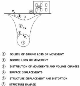
Tunnel construction frequently occurs in urban areas where many buildings already exist and damage of the buildings can be induced due to tunnelling-induced ground movements. The causes of ground loss include over excavation, delayed support and grouting installation, support deflection, and face instability such as raveling or flowing (Fig. 1). Surface ground movement is also affected by the volume change of soil mass over tunnel and outside tunnel spring line due to the state of stress change.
One can evaluate the building response in steps from the source of ground loss around tunnel to their effect on the buildings (Fig. 2) and therefore, it is important to understand the entire mechanism from ground loss to building response. Tunneling-induced free-field ground movements can be modified by
pre-existing structures. Relative stiffness of structure and soil and strength of soil and structure are among the main factors that affect the modification of a free-field ground movement. Estimates of building response that consider these soil-structure interactions may be significantly different from estimates that assume a structure deforms with a free-field ground movement.
In addition, structures subjected to self-weight settlement generally undergo vertical displacement predominantly, whereas structures subjected to tunnelling are exposed to both vertical and horizontal displacements in which structures can be damaged severer. Therefore, the influence of the horizontal ground displacement on a structure should be considered when assessing building damage.
Fig. 1. Source of ground movements
Fig. 2. Progress from tunnelling to structure damage
3. PATTERNS OF GROUND MOVEMENT DUE TO TUNNELLING
To assess building damage of structures to tunnelling, the surface ground movements should be reasonably estimated where structures are located. The estimation of ground movements should include the horizontal displacement as well as the vertical displacement (settlement).
3.1 Estimating surface settlement
The settlement profile due to tunnelling can be reasonably estimated by the Gaussian distribution curve (Schmidt, 1969, Peck, 1969) as described in Fig. 3. To draw the settlement curve the maximum surface settlement (δmax) should be known and it can be determined by dividing the surface settlement volume (Vs) by the trough half width (W). The surface settlement volume (Vs) in sandy soils can be determined by the relationship with the volume loss (VL) around tunnel (Fig. 4). In soft clay, the surface settlement volume is approximately equal to the volume loss for the unconsolidated condition (short term condition), but it is relatively bigger than the volume loss after consolidation. The maximum surface settlement (δmax) can be also estimated in the other way using the ratio with respect to the tunnel crown settlement (δc) considering the tunnel and ground conditions (Fig. 5a, b, c). The figure was developed based on field observations and numerous numerical tests (Son and Yun, 2009). The crown settlement (δc) can be determined using the expected volume loss (VL) in a tunnel construction as explained in Fig. 6.
Fig. 3. Estimation of surface settlement
Fig. 4. Relationship between the volume loss (VL) and the
a) Volume loss, VL = 0.5%
b) Volume loss, VL = 2%
c) Volume loss, VL = 5%
Fig. 5. Ratio between maximum surface settlement (δmax)
and tunnel crown settlement (δc) considering tunnel and
ground conditions (Son and Yun, 2009)
Fig. 6. Determination of tunnel crown settlement, δc
3.2 Estimating lateral surface displacement
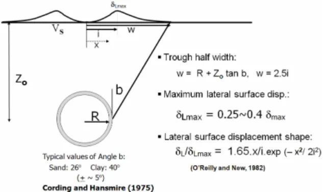
The lateral surface displacement can have a significant effect on the damage to structures. However, lateral surface displacements have not been commonly measured in field and there is not enough field data and information to estimate the lateral surface displacement profile with the same degree as the settlement profile. Nevertheless, O’Reilly and New (1982) proposed a method to estimate the lateral displacement profile (Fig. 7), which was developed based on the Gaussian settlement function (Schmidt, 1969, Peck , 1969) with the assumption that there is no volume change in the soil mass and the displacement vectors direct toward the center of the tunnel. It is described as
, 65 . 1 ( /2 ) max 2 2 i x L L e i x⋅ − ⋅ =δ
δ where δL =lateral displacement at a distance from tunnel center line, δLmax = maximum lateral displacement, x = a distance from tunnel center line, and i = inflection point).
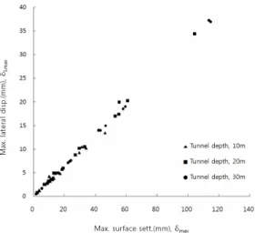
Cording (1991) reported that if the equation for estimating lateral displacement is used, the lateral displacement at the edge of settlement profile can be estimated smaller than real displacement. Maximum lateral displacements (δLmax) develop near the point of inflection, i, of the settlement trough. The results of field studies by Cording and Hansmire (1975) and Attewell (1977) show that the maximum lateral displacements are in the range of 0.25 to 0.4 times the maximum vertical displacements. From the numerous numerical tests, Son and Yun (2009) have also shown the maximum lateral displacements are approximately 0.35 times the maximum vertical displacements (Fig. 8), which are consistent with the field observations.
Fig. 8. Estimation of maximum surface lateral displacement (Son and Yun, 2009)
4. BUILDING DISTORTION AND DAMAGE
4.1 Damage criterion for assessing building distortion and damage
The structure is strained by the ground movement acting along its base (Fig. 9). The angular distortion, or shear strain, is equal to the average settlement slope minus the tilt of a structural bay or unit. The lateral strain at the base is equal to the extension of the base divided by the base length. Separate values of lateral strain may be estimated for the lower and upper portions of the building unit. In the upper portions of the building, lateral strains may reduce due to the stiffness and restraint provided by the upper floors, or, conversely, they may increase due to bending or rotation for a convex (hogging) soil settlement profile, and will concentrate in areas where the building is weak in tension.
Son and Cording (2005) proposed a generalized damage estimation criterion based on the state of strain at a point or an average strain across a building unit (Fig. 10). With some modification of the criterion established by Boscardin and Cording (1989), the modified damage criterion can be applied to the structures with any L/H (building length/building height) and E/G (building longitudinal stiffness /building shear stiffness). The criterion is based on the concept that a structure is deformed by the combination of angular distortion and lateral strain, and the maximum strain on the structure can be decided by a principal strain formed by both the angular distortion and the lateral strain (see Fig.9). Each boundary in Fig. 5 represents a constant value of maximum principal extension strain and the results of field observations (Skempthon and MaCdonald, 1956, Polshin and Tokar, 1957, Burland and Wroth, 1974) have been used to determine the strain value of each boundary between the different damage levels
Fig. 9. Angular distortion and lateral strain in a structural element due to ground movement (Son and Cording, 2005)
Fig. 10. State of strain damage estimation criterion (Son and Cording, 2005, modified after Boscardin and Cording, 1989)
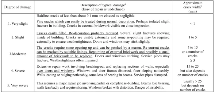
Each damage categories was described by Burland et al (1977) (Table 1). Burland (2008) stated “The strong temptation to classify the damage solely on crack width must be resisted. It is the ease of repair which is the key factor in determining the category of damage.”
The categories are summarized as follows:
Aesthetic damage, including very slight to slight damage, affects interior finishes. Slight damage may require some re-pointing of visible masonry cracks. Redecoration may be required.
Moderate damage affects building function and results in masonry cracks requiring patching and may require some re-pointing of brickwork.. “Doors and windows stick, service pipes may fracture, and weather-tightness is often impaired.”
Severe and Very Severe categories result in structural damage. Severe damage involves… “breaking-out and replacing of sections of walls, especially over doors and windows, distorted windows and frames, sloping floors, leaning or bulging walls, some loss of bearing in beams and disrupted service pipes.” “Very severe damage often requires…partial or complete rebuilding, beams lose bearing, walls lean and require shoring, and there is a danger of structural instability.” It is understood that the impact of a given distortion will differ for different buildings, depending on their sensitivity and significance, and they should be evaluated on a case by case basis. As Burland (2008) notes, the descriptions relate to standard domestic and
Table 1. Classification of visible damage to walls with particular reference to ease of repair of plaster and brickwork or masonry (after Burland et al., 1977)
office buildings and may not be appropriate for a building with valuable or sensitive finishes. (Plaster finishes such as crown moldings particular concern in the aesthetic damage range.)
Burland (1995) has also presented a damage estimation criterion (Fig. 11) using deflection ratio (Δ/L, see Fig. 9) and horizontal strain (εh). The criterion was based on a simple deep beam theory with L/H = 1 and E/G = 2.6.
Horizontal strain (%) 0.0 0.1 0.2 0.3 0.4 D eflec tio n r atio Δ /L ( % ) 0.0 0.1 0.2 0.3 0.4
SEVERE TO VERY SEVERE DAMAGE MODERATE DAMAGE SLIGHT DAMAGE VSL. NEGL.
Fig. 11. Damage estimation chart (Burland, 1995) The observed damages obtained from field observations, physical model tests and numerical studies (Son, 2003) were compared with damage estimates from both the generalized damage estimation criterion (Son and Cording, 2005) and Burland’s criterion. Figs. 10 and 11 show the comparison between observed damages and estimated damage levels using the two different criteria. The comparison clearly shows the generalized state of strain damage criterion estimates building damage reasonably well for the observed damages, but Burland’s criterion underestimates the observed damages. The reason for
this underestimation is that the value of deflection ratio does not consider tilting of a structure, which is an important factor in relation to building distortion.
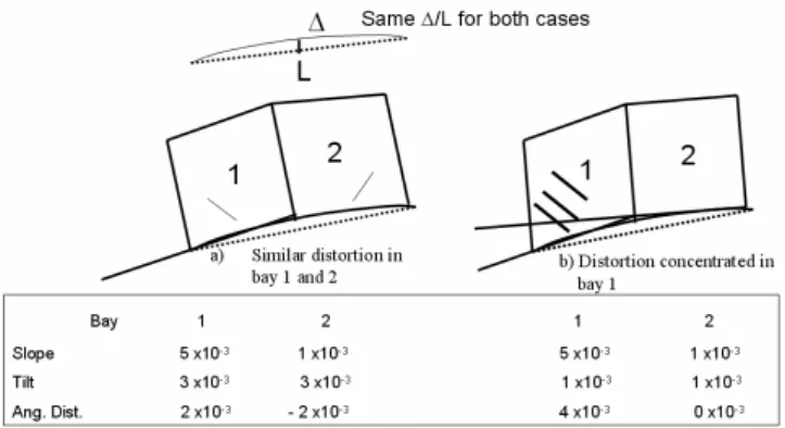
Fig. 12 shows the response of two different structures. The structures were subjected to the same ground settlement profile, so that the structures had the same deflection ratio (∆/L). However, the two structures distorted very differently as indicated in the figure. Response comparison of the two structures indicates the importance of tilt in a structure distortion. In other words, when evaluating building distortion, the effect of tilt should be considered, and thus, the deflection ratio, which does not consider the effect in relation to structure distortion, may not be an appropriate parameter for building damage estimation.
In a beam analysis the tilt of the structure is assumed equal to the slope of the chord extending across the settlement profile. The slope of the chord is considered in much of the literature to represent the structure’s tilt, and damage criteria based on the deflection ratio, Δ/L make this assumption. However, the actual tilt should be measured from the tilt of vertical sections within the structure. The deflection ratio damage criterion proposed by Burland (1995) based on beam theory is consistent with the damage criterion based on angular distortion for the elastic condition of a structure, but it underestimates the damage level for the conditions of cracked structure.
The series of numerical analyses by Son (2003) showed the ratio [β/(Δ/L)] between the angular distortion (β) and the deflection ratio (Δ/L) ranged between 2 and 4. For elastic (including frame structures) and slightly cracked structures, the ratios were in the range of 2, but for severely cracked structures, the ratios increased up to 4.
Degree of damage Description of typical damage(Ease of repair is underlined) a
Approximate crack widthb
(mm) Hairline cracks of less than about 0.1 mm are classed as negligible.
1. Very slight Fine cracks which can easily be treated during normal decoration. Perhaps isolated slight fracture in building. Cracks in external brickwork visible on close inspection. < 1
2. Slight
Cracks easily filled. Re-decoration probably required. Several slight fractures showing inside of building. Cracks are visible externally and some re-pointing may be required externally to ensure weathertightness. Doors and windows may stick slightly.
1 to 5
3.Moderate
The cracks require some opening up and can be patched by a mason. Re-current cracks can be masked by suitable linings. Repointing of external brickwork and possibly a small amount of brickwork to be replaced. Doors and windows sticking. Service pipes may fracture. Weathertightness often impaired.
5 to 15 or a number of
cracks ≥ 3 4. Severe Extensive repair work involving breaking-out and replacing sections of walls, especially over doors and windows. Windows and door frames distorted, floor sloping noticeably.
Walls leaning or bulging noticeably, some loss of bearing in beams. Service pipes disrupted.
15 to 25 but also depends on number of cracks 5. Very severe This requires a major repair job involving partial or complete re-building. Beams lose bearing, walls lean badly and require shoring. Windows broken with distortion. Danger of instability. but depends on usually > 25
number of cracks aIn assessing the degree of damage account must be taken of its location in the building or structures.
Fig. 12. Response comparison between two different structures
4.2 Assessing angular distortion and lateral strain in a structure
To assess building damage using the damage criterion (Son and Cording, 2005), the angular distortion and lateral strain which are induced in a structure should be assessed. Even though the influence of soil-structure interaction on building distortion is discussed in detail in the next section, for now, the angular distortion and lateral strain will be determined assuming a structure is perfectly flexible and conforms to the ground movement pattern completely, which is a conservative approach. Fig. 13a, b, and c describe of how to assess angular distortions in three possible conditions encountered in the field and Fig. 13d describes of how to assess lateral strains.
a) Building moves with ground and extends beyond settlement zone
b) Building moves with ground and narrow enough to tilt, distortion concentrated in unit 1
c) Building moves with ground and narrow enough to tilt, frame is subject to side sway, which increase tilt
d) Determination of lateral strain
Fig. 13. Assessment of angular distortion and lateral strain in a structure
5. FIELD OBSERVATIONS AND NUMERICFAL TESTS OF GROUND MOVEMENTS AND BUILDING RESPONSE
5.1 Field observation
Breth and Chambosse (1974) observed the responses of structures due to tunnelling-induced ground movements in Frankfurt, German. The tunnels were constructed through heavily overconsolidated and laminated clay interbedded with bands of jointed limestone, silts and water-bearing sands. The diameter of tunnels was 6.7m and the overhead cover was 10-12m. During the construction ground water table was dropped by 20m. Settlements were measured in both free-field surfaces and buildings above the tunnels. Fig. 14 shows one of the investigated structures, which was a brick structure. The settlement slope of the structure was much less than the free-field settlement profile because the ground settlement was significantly modified by the structural stiffness and self-weight. Free-field ground displacement profile may be modified by many factors such as soil stiffness, structure stiffness, foundation type, structure strength, and the structure load. The influence of these factors should be considered for assessing building damage, which is the problem of soil-structure interaction.
Fig.14. Field observation of a structure in Frankfurt, German (Breth and Chambosse, 1974)
5.2 Numerical tests
Numerical tests were performed to investigate the effect of soil-structure interaction on the structure response. Two structures were subjected to all the same conditions except for the soil stiffness. The brick-bearing structures were modelled using a distinct element code (UDEC, 2001) in which each brick was modelled as a block element and the mortar was modelled as the contact shear and normal stiffness and strength between blocks. With this modelling, the brick structures can accept large displacements, and the mortar will crack and bricks separate. A parabolic pattern of ground settlement was imposed on a system of elastic soil mass modelled beneath the structures. Lateral and vertical displacements at the top and base of the wall were recorded at four sections (A, B, C and D) along the length of the building wall. From this data were obtained the tilt and angular distortion and their variation along the length of the wall, as well as lateral strains at both the base and top of the wall. The tilt and bending could not be determined from a settlement profile alone, but required the measurement of lateral displacement over the height of vertical sections along the wall.
Fig. 15. Effect of soil stiffness in 4-story brick-bearing walls (Son, 2003)
The structure on dense soil had a deflection pattern close to the free-field soil displacement due to severe structure cracking, whereas loose soil was modified with a flatter settlement profile and smaller angular distortion with respect to the change in ground slope was induced in the structure on loose soil. Fig. 15 clearly shows the effect of soil stiffness on the structure response. In other words, the response of structures to tunnelling is a problem of soil-structure interaction and the effect should be considered for building damage estimate.
6. CONSIDERATION OF SOIL-STRUCTURE INTERACTION
6.1 Reduction in angular distortion due to building stiffness
As indicated previously, to estimate building damage based on the generalized state of strain criterion, angular distortion and lateral strain need to be determined. If the angular distortion and lateral strain are determined from a free-field ground settlement profile, it may be a conservative approach for building damage estimate because a pre-existing building may modify the free-field ground settlement profile. In other words, if a building is stiff and strong enough to modify a free-field ground settlement profile, the estimate based on the free-field ground settlement profile can cause unnecessary and expensive protection measures. Accordingly building response should be evaluated based on the soil-structure interaction to provide more reasonable damage estimates.
Parametric studies using a series of UDEC analyses were conducted to evaluate the reduction in the ratio of angular distortion, β, with respect to the change in free-field ground slope, ΔGS, between adjacent structural units. The change in ground slope, ΔGS, is determined from the free-field ground movement slopes at the location of two adjacent units, one of which is the unit for damage estimation, and the other being the unit adjacent to it. ΔGS is obtained by subtracting the slope of the latter from the slope of the former.
It was found that the ratio (β/ΔGS) depends on the relative soil/building shear stiffness (ESL2/GHB), where Es is soil stiffness, L is the distorted span of the structure, length of building portion subjected to ground movement, G is the effective shear stiffness of the building, including reduced stiffness due to window penetration, H is building height, and B is the width of building wall. Increasing values of soil/building shear stiffness (decreasing structure stiffness) cause the building distortion to conform more closely to the ground settlement profile, and the ratio of β/ΔGS to approach one. Son and Cording (2007) describes in detail of how to determine the effective shear stiffness (G) in various building conditions. The building will also become more compliant with the ground settlement profile as cracks in a structure form and open. Cracking
will be a function of the magnitude of the strain imposed on the structure with respect to the strains required to initiate cracks and is quantified in terms of the change in ground slope with respect to structure cracking strain (ΔGS/εt).
Fig. 16 shows the relationship among the normalized angular distortion (β/ΔGS), the relative shear stiffness (ESL2/GHB), and the ratio (ΔGS/εt) between ground movement slope change and structure cracking strain. The figure clearly shows four trends. One trend is that the value, β/ΔGS, gradually increases as the relative soil/structure shear stiffness increases (and the structure shear stiffness decreases) if no cracks, or minor cracks, form in a structure. The building conforms more closely with the free-field ground settlement slope when the building is very flexible, and the value of GHB is small. In that case, the building will conform to a free-field ground settlement and β/ΔGS will approach one. The second trend is that when a building is cracked extensively, the effective building stiffness is no longer described by elastic stiffness alone, because the extent of cracking strongly controls the effective building stiffness. The value of β/ΔGS in this case becomes close to one. For moderate cracking, the value of β/ΔGS is between values for no or minor cracking and values for extensive cracking. The third trend is related to structure strength and shows that the value of β/ΔGS increases as the ratio between ΔGS and εt (structure cracking strain), ΔGS/εt,
increases for the same relative stiffness. In other words, the greater the change in ground slope and the weaker the structure, the larger the value of β/ΔGS. The fourth trend is related to the effect of downdrag force from an adjacent façade wall. The trend shows that a structure subjected to a downdrag force has higher β/ΔGS for the same relative stiffness.
Fig. 16. Relationship among the normalized angular distortion (β/ΔGS), the relative shear stiffness (ESL2/GHB), and the ratio (ΔGS/εt) between ground
movement slope change and structure cracking strain (Son and Cording, 2005).
Lower values of β/ΔGS were obtained for the various combinations of higher-story buildings, higher tensile strength, fewer window openings, smaller change in ground slope, less downdrag force, and stiffer structures with respect to the soil.
For a medium to stiff soil, and structure with lime rich mortar (type N), the soil/wall shear stiffness is ESL2/GHB = 10. For this stiffness, cracking results in β/ΔGS = 1. The value of β/ΔGS reduces to less than 0.5 only for elastic deformations or for very small cracks at very low values of ΔGS. For a stiffer wall or softer soil (EsL2/GHB = 1), β/ΔGS = 1 for larger changes in ground slope (ΔGS > 3x10⁻³) and β/ΔGS reduces to less than 0.5 for ΔGS < 1.5x10⁻³ (Son and Cording, 2005, Cording et al, 2008).
6.2 Reduction in lateral strain due to grade beam or foundation stiffness
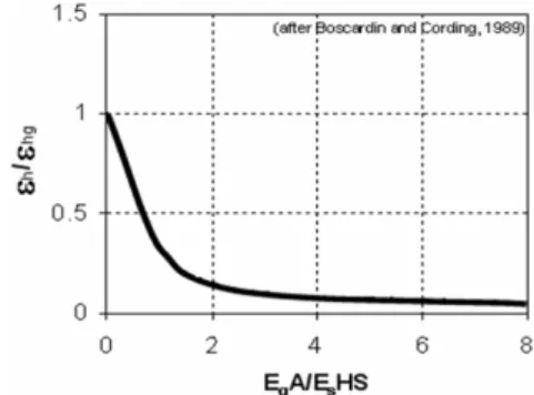
Boscardin and Cording (1989) give a relationship (Fig. 17) between the reduction in lateral building strain(εh) from the free-field lateral ground strain (εhg) and the axial beam/soil stiffness of grade beams. The greatest benefit was found when going from no grade beams to a light grade beam. The relationship can be used to consider the effect of grade beams on strain in a structure induced by lateral ground movement due to open cutting, but the concept of the reduction in lateral building strain can still be applied to tunnelling-induced lateral ground movement.
Large reductions in lateral strain imposed by the ground will result if the foundation has grade beams, reinforced wall footings, or structural slabs on grade. In such cases, the lateral strain across the structural unit can be assumed zero. Additionally, the lateral strain imposed by the ground or by bending in the upper portions of a building will be reduced if the upper floors are reinforced and tied to the walls.
Fig. 17. Effect of grade beam on lateral strain
7. BUILDING DAMAGE ASSESSMENT PROCE- DURE
Protection of adjacent or overlying structures occupies a major part of the cost, schedule and third-party impacts of urban underground construction. Methods used to prevent or mitigate the impacts on
nearby buildings include siting to avoid the structure; limiting movements at the excavation source with controlled construction measures; modifying the ground or using compensation methods to replace ground loss; and underpinning, reinforcing, repairing or replacing structures. Predicting, and then monitoring building performance is a key aspect in planning, design, and implementation of such measures.
There are several levels in evaluating the effect of ground movements on building performance. An initial screening determines the structures, which may be potentially affected, along the project alignment by considering the width, maximum settlement and ground slopes of the free-field trough. For example, Rankin (1988) notes negligible damage would be expected for slopes less than 1/500 and settlements less than 10 mm.
A second level of investigation is to consider the location of the building and its width with respect to the settlement trough and estimate lateral strains and distortions by imposing the anticipated ground displacements on the building. Making the conservative assumption that the structure is flexible enough to be compliant with the ground is most appropriate for masonry structures that are not tied or reinforced. Distortion can be estimated by integrating curvature across a length of a structural unit, but in practice it is appropriate to consider differential slopes between structural units, recognizing that the structure is stiff enough to distribute loads and smooth out locally high or abrupt curvatures.
A further level of investigation is to consider the ability of the building to modify ground movement patterns; in particular, to consider the axial stiffness of grade beams or the structural frame which limits lateral strains, and the shear and bending stiffness of the building with respect to the soil which causes the angular distortion of the structure to be lower than the distortions determined from the free-field settlement profile. Additionally, the geometry and variations in stiffness and strength of the structure, and its tolerance for different levels of distortion and damage, should be considered.
From the outlined points, the overall building damage assessment procedure is described below. The procedure goes on in steps from the most conservative approach to the most specific approach to allow a number of buildings in urban areas to be investigated in a limited time. The following outlines the process of evaluating potential distortions and damage.
I. First Assessment Phase
1. Estimate a free-field ground movement, both vertical and horizontal movements from empirical or semi-empirical relationships, physical model tests, or numerical tests.
2. Determine if the structure is within the zone of the ground movement profile.
3. If so, determine the maximum settlement and settlement slope expected across the structure.
4. For most structures, if the maximum settlement or slope is smaller than the allowable limit (Rankin, 1988), the investigation may finish at this step. However, if the maximum settlement or slope is greater than the allowable limit, proceed to the second assessment phase.
II. Second Assessment Phase
5. Use the free-field ground movement and assume that a structure conforms to the free-field ground movement.
6. Determine the change in ground slope (ΔGS) between adjacent sections based on column spacing, footing spacing, cross-wall spacing, or ground movement gradient. Assume that the change in ground slope (ΔGS) is equal to angular distortion (β).
7. Determine the horizontal (lateral) free-field ground strain (εhg) between adjacent sections based on column spacing, footing spacing, cross-wall spacing, or ground movement gradient.
8. If major pre-existing vertical joints or weaknesses are present in the structure, determine the bending (lateral) strain (εL = H/R) at the top of a building unit, using the height of the building unit (H) and the radius of a curvature of ground movement (R).
9. Using the angular distortion and lateral strain, determine the damage level from the generalized state of strain damage criterion (Fig. 10).
10. If the damage level assessed from the state of strain criterion is acceptable, finish at this step. If it is unacceptable, proceed to the final assessment phase.
III. Final Assessment Phase
11. Use the change in ground slope (ΔGS) of the free-field settlement determined at the step 6.
12. Determine the relative shear stiffness between soil and structure and find the normalized angular distortion (β/ΔGS) from Fig. 16 and in turn determine the angular distortion (β), which would be induced in a structure. 13. From the lateral ground strain obtained at the step 7, determine the reduced lateral strain (εL) considering the effects of grade beam or reinforced foundation (refer to Fig. 17). If major pre-existing vertical joints or weaknesses are present in the structure, determine the bending (lateral) strain as εL = H/R, where H is the height of the building unit and R is the radius of a curvature of ground movement.
14. Find a damage level from the generalized state of strain damage criterion (Fig. 10) using the angular distortion and lateral strain determined from step 12 and step 13.
15. If the damage level at the step 14 is acceptable for a project, finish at this step. If this is unacceptable, find appropriate protection measures or means.
IV. Protection Phase
16. Find a protection scheme to prevent damage or limit damage to acceptable levels.
a) At source of ground movements (tunnel or excavation)
b) Ground modification/replacement c) Building reinforcements
8. CONCLUSION
This paper discussed tunnelling-induced ground movements and their impacts on nearby buildings, including the importance of the soil-structure interactions. In addition, a building damage criterion, which is based on the state of strain, was presented and discussed in detail. In addition, the overall assessment procedure was provided for the assessment of tunnelling-induced building damage considering the effect of soil-structure interaction.
To properly assess building response and behavior in both distortion and damage, it is important to understand the whole mechanism from tunnelling to building damage, including not only the ground movement patterns but also the building’s structural characteristics.
REFERENCES
1) Attewell, P. B. (1977). “Ground movements caused by tunnelling in soil.” Proc., Conf. on Large Ground Movements and Structures, Halstead Press, New York, N.Y., pp. 812-948. 2) Boscardin, M. D. and Cording, E. J. (1989). “Building
response to excavation-induced settlement.” ASCE Journal of Geotechnical Engineering Division, Vol. 115, No. GT1, pp. 1-21.
3) Breth, H. and Chambosse, G. (1974). “Settlement behavior of buildings above subway tunnels in Frankfurt clay.” Proc., Conf. on Settlement of Structures, Pentech Press, London, England, pp. 329-336.
4) Burland, J. B., 1995. “Assessment of risk of damage to buildings due to tunneling and excavation.” Proceedings of 1st International Conference on Earthquake Geotechnical
Engineering, IS-Tokyo, Japan, pp. 495-546. 5) Burland, J. B. (2008). “The assessment of the risk of
damage to buildings due to tunnelling and excavation.” Jornada Techica 16-12-08, Movimientos de Edificios Inducidos por Excavationes: Criterios de dano y gestion del riesgo. Escola Technica Superior d’ Enginyers de Camins, Canals I Ports de Barcelona, Universitat Politechnica de Catalunya.
6) Burland, J. B. and Wroth. C. P. (1974). “Settlement behavior of buildings and associated damage.” Proc., Conf. on Settlement of Structures, Pentech Press, London, England, 611-654.
7) Burland, J. B. and Broms. B. B., and de Mello, V. F. B. (1977). “Behavior of foundations and structures.” State of the Art Report. Proc., 9th Int’l Conf. on Soil Mech. and
Foun. Engr., II, Tokyo, Japan, pp. 495-546.
8) Cording, E. J. (1991). “Control of ground movements around tunnels in soil.” Ninth Pan American Conference, Vina del Mar, Chile. Sociedad Chilena de Geotechina, Vol. 4, pp. 2195-2244.
9) Cording, E. J. and Hansmire, W. H. (1975). “Displacements around soft ground tunnels.” General Report, Session 4, 5th
Panamerican Cong. on Soil Mech. and Foun. Engr. Buenos Aires, November.
10) Cording, E. J., Son, M., Laefer, D. F., Long, J. H., and Gharreman, B. (2008). “Examples of building response to excavation and tunnelling.” Jornada Techica 16-12-08, Movimientos de Edificios Inducidos por Excavationes: Criterios de dano y gestion del riesgo. Escola Technica Superior d’ Enginyers de Camins, Canals I Ports de Barcelona, Universitat Politechnica de Catalunya.
11) Hong, S. W. (1984). “Ground movements around model tunnels in sand.” Ph.D. Thesis, University of Illinois, Urbana, IL. USA.
12) O’Reilly, M. P. and New, B. M. (1982). “Settlements above tunnels in the United Kingdom – their magnitude and effects.” Tunnelling ’82, M. J. Jones, ed., London, England, pp. 173-181.
13) Peck, R. B. (1969). “Deep excavations and tunneling in soft ground.” Proc. 7th Int’l Conf. on Soil Mech. and Foun. Engr.,
Mexico City, State-of-the-Art, pp. 225-290.
14) Polshin, D. E. and Tokar, R. A. (1957). “Maximum allowable non-uniform settlement of structures”, Proc., The 4th Int’l Conf. on Soil Mech. and Foun. Engr., Butterworth,
England, Vol 1, pp. 402 - 405.
15) Schmidt, B. (1969). “Settlements and ground movements associated with tunneling in soil.” Ph.D. Thesis, University of Illinois, Urbana, Illinois.
16) Skempton, A. W. and MacDonald, D. H. (1956). “The allowable settlement of Buildings.” Proc., Inst. of Civ. Engrs., III, 5, pp. 727-784.
17) Son, M., 2003. “The response of building damage to excavation -induced ground movements.” Ph.D. Thesis, University of Illinois at Urbana-Champaign.
18) Son, M. and Cording, E. J., 2005. “Estimation of building damage due to excavation-induced ground movements.” J. Geotech. Engrg., ASCE, 131(2), pp. 162-177.
19) Son, M. and Cording, E. J., 2007. “Evaluation of building stiffness for building response analysis to
excavation-induced ground movements.” J. Geotech. Engrg., ASCE, 133(9), pp. 995-1002.
20) Son and Yun, 2009. “Numerical Analysis of Tunnelling- Induced Ground Movements.” Tunnelling Technology, KTA, 11(3), pp. 229-242.
21) UDEC 3.1, 2001. “Theory and manual.” Itasca Consulting Group, Inc, MN.