This work is supported by the Natural Science Foundation of Fujian Province (2020J01711), Li Shangda Discipline Construction Fund (ZC2016008), and Research Start-up Fund of Jimei University (ZQ2019021).
http://doi.org/10.3837/tiis.2021.03.017 ISSN : 1976-7277
Analysis of Antenna Selection in Two-way
Relaying MIMO Systems with CPM
Modulation
Guowei Lei1, Hailan Chen1*, and Yuanan Liu2 1 School of Science, Jimei University
Xiamen 361021, China
[e-mail: [email protected], [email protected]]
2 School of Electronic Engineering, Beijing University of Posts and Telecommunications Beijing 100876, China
[e-mail: [email protected]] *Corresponding author: Hailan Chen
Received November 18, 2020; revised January 3, 2021; accepted February 11, 2021; published March 31, 2021
Abstract
Up to now, many state-of-arts have been proposed for two-way relaying system with linear modulations. The performances of antenna selection (AS) at both transmit and relay nodes need to be investigated in some two-way relaying multiple-input multiple-output (TWRM) systems. In this paper, the goal is focused on the study of nonlinear modulations, i.e., continuous phase modulation (CPM) in TWRM systems. Firstly, the joint phase trellis are simplified by reversed Rimoldi processing so as to reduce the systems’ complexity. Then the performances of joint transmit and receive antenna selection (JTRAS) with CPM modulations in two-way relaying MIMO systems are analyzed. More exactly, the pair wise probability (PEP) is used to evaluate the error performance based on the CPM signal matrix, which is calculated in terms of Laurent expression. Since the channels subject to two terminal nodes share common antennas at relay node R in multiple-access scheme, we revise the JTRAS algorithm and compare it to existing algorithm via simulation. Finally, the error performances for various schemes of antenna selection are simulated and compared to the analysis in this paper.
Keywords:
Two-way Relaying Multiple-input Multiple-output, Continuous Phase Modulation, Joint Transmit, Receive Antenna Selection1. Introduction
S
ince put forward in 2000 [1], Network coding (NC) has received a lot of attention because itcan enlarge the throughput by exploiting a max-flow min-cut bound in a multicast system [2].
Although it was aimed at network layer in internet technology originally, it is applied to wireless communication now [3-11]. Using the physical-layer network coding (PLNC)
protocol,two terminals transmit simultaneously through multiple access channel (MAC) [5]. There are two ways of PNC in implementation: one way is to use the relay to amplify and forward the received signal from the terminals without demodulation and decoding (ANC) [3]. The other is to employ the relay to demodulate and decode the received signal and then broadcast its estimate of the network codeword [4], i.e. digital network coding (DNC). As the
noise may be amplified by the relay when ANC is used, DNC can offer better performance than ANC under many channel conditions.
The typical wireless network employing NC is the two-way or bidirectional relay channel, which is a three-terminal network with two source nodes A, B and one relay R. The working mode is under a half-duplex constraint, and there is no direct link in the multi-access (MA) scheme. The modulation method is one of the most challenging issues for the PLNC systems. In fact, most of previous literatures focus on the linear modulation methods, such as PSK, PAM and QAM [6-11], which may not be the best option for power strictly limited PLNC wireless communications. In [12], Yu et al, investigated 2FSK and M-FSK in PLNC wireless communications, and drew comparisons between PSK, QAM and FSK. To exploit the phase continuity in decoding, a joint CPFSK modulation and PLNC was proposed in two-way relay systems [13].
Continuous phase modulation (CPM) is a charming technology with constant envelope and phase continuity. Because of its constant envelope, it is more suitable for low-cost nonlinear power amplifier, and its phase continuity makes its bandwidth more compact.Due to its advantages, CPM signal has practical importance in satellite and ground communication. In particular, one of its subcategories, GMSK, is well suited for GSM and DECT standards. However, the detection method proposed in [13] should bring high complexity at relay node R due to the joint phase trellis of CPFSK signal. On the other hand, multiple input multiple output (MIMO) can significantly provide apparent reliability in multipath fading channels. Therefore, some two-way relaying MIMO systems have been introduced and analysed recently [14-16]. Among them, an MIMO-PLNC scheme is originally proposed as a network-coded form by the summation and difference of the two source signals [14]. It is worth noting that the deployment of multiple antennas will bring comparable cost of multiple RF chains in implementation. To alleviate the problem, a technique known as antenna selection (AS) is considered to be a promising solution. To our knowledge, most two-way relaying MIMO systems focus on one-sided antenna selection, e.g. transmit antenna selection
[17], relay antenna selection [18], or both of them [19].
In view of the above problems, the contributions of this paper lie in: firstly, we simplify the joint phase trellis by reversed Rimoldi processing so as to reduce the systems’ complexity. Secondly, we derive the error performances of CPM modulation in two-way relaying MIMO systems. Thirdly, we evaluate the performance of joint transmit and receive antenna selection (JTRAS) with CPM modulations in two-way relaying MIMO systems. Since the channels subject to two terminal nodes share common antennas at relay node R in MAC scheme, we revise the JTRAS algorithm and compare it to existing algorithm via simulation.
The rest of the paper is arranged as follows: section II describes the system model, and proposes a novel detection method using simplified joint trellis combining. In section III, the performances of frame error rate (FER) and outage probability (OP) are analysed. Further, the criteria of antenna selection at nodes A, B and R are introduced for five cases. Especially, an improved algorithm is proposed for JTRAS in this system. In section IV, simulations are presented and analysed. Finally, section V gives the conclusion.
Some notations are used to avoid confusion. In the manuscript,
=
−
1
j
represents an imaginary number. Unless otherwise specified, bold letters are denoted as vectors or matrices. (⊕) represents exclusive OR between two logic numbers. Superscripts (*), (T) and (H) aredenoted as matrix conjugate, matrix transpose and conjugate transpose. In addition to these, ||(·)|| is the Euclidian vector norm.
2. System Model
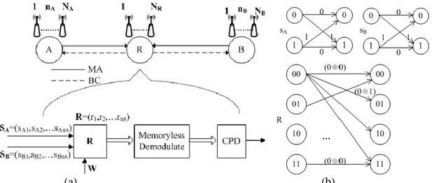
The two-way relaying MIMO system with CPM modulation is described in Fig. 1. The nodes
A, B and R are equipped with NA, NB, NR antennas respectively. In the first stage, two terminal
nodes (A and B) simultaneously transmit CPM signals to relay R, i.e. multi-access (MA) scheme. At the second stage, the relay R broadcasts CPM signal to the two nodes A and B. In this paper, we focus on the former stage, i.e. multiple-access (MA) stage. Owing to channel state estimation, the TAS strategy can be availably employed to improve the error performance. At MA stage, terminal node A selects nA from NA antennas, and terminal node B
selects nB from NB antennas. It is assumed that the channel state information (CSI) remains
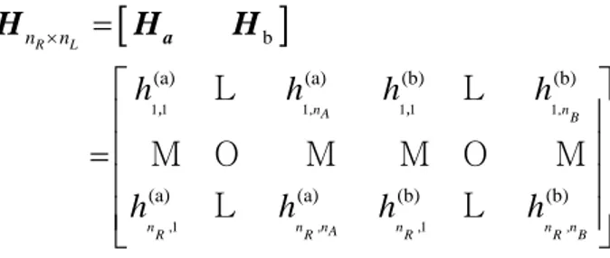
constant within one frame.The quasi-static channel from user m to relay R can be expressed as an NR×Nm matrix Hm 1 1 1 2 1, 2 1 2 2 2, ,1 ,2 , m m R R R m N N N N N N h h h h h h h h h = , , , , m H L L M M O M L (1)
Where the entries of Hm are independent and identically distributed (i.i.d), nA∈{1,2,…,NA}, nB∈{1,2,…,NB}, m∈{A, B}.
The superimposed signals at the relay node R can be written as
R=H sA A+H sB B+wR (2) Where sA=(sA1,sA2,…,sAnA), sB=(sB1,sB2,…sBnB), R=(r1,r2,…,rnR), wR represents the added white
(a) (b)
Fig. 1. Two-way relaying MIMO system with CPM modulation via transmit antenna selection
(a) Multi-access decoding with two-way relaying MIMO system (b) Decoding via joint trellis combining
The complex form for baseband CPM signal can be given as [20]
0 ( ) s (φ( ) θ ) s t;D = E exp j t;D + (3) and
( )
t; D 2hp D q tn(
nT)
+ − =
− (4) where Es denotes the power of CPM signal, {Dn} denotes the sequential and independentinformation symbols drawn from {±1,±3,…, ±(M-1)}, 0 denotes the initial phase, q(t) is the phase smoothing response, T denotes the symbol period, the modulation index hp should be
a rational fraction ,i.e. hp=J/p.
In [13], a two-way relay scheme is developed by combining CPFSK modulation and physical layer network coding, where the superimposed signal at relay node R can be decoded via Viterbi algorithm. As hp=2/3 was used in [13], the number of states in joint trellis graph
should be 3×3=9. It is obvious that various hp may incur certain amount of states. To reduce
the number of states, it is available to employ Rimoldi decomposition [21], where a model of CPM is generally divided into the continuous phase encoder (CPE) and the memoryless modulator (MM). While in this paper, the model at the relay node R can be reversed to consist of memoryless demodulator (MD) and continuous phase decoder (CPD). As shown in Fig. 1, the number of joint state trellis should always be 4 (M=2) regardless of hp.
To determine the form of CPD and MD, (4) may be written as
( )
(
)
( )
(
)
0 1 2 4 2 1 n L n i i i i n L p p t; D h D mod p h D q t iT Z t mod , nT t n T − = = − + = + − + +
(5)( )
(
)
(
) (
)
(
)
(
)
1 1 2 1 1 1 n p p i n L Z t M h q t iT M h n L , nT t n T = − + = − −
− − − − + + (6)Then, Viterbi algorithm can be employed according to (5). Hence, the complexity is greatly reduced.
3. Performance Analysis of the System
3.1 Analysis of Frame Error Rate (FER) and Outage Probability (OP)
To analyse the performance of TWRM systems, the pair wise probability conditioned onto fading channel statistics can be expressed as [22, 23]
0 ( ) Q( ( ) ) 2 s E p N → ˆ = − ˆ S S | H H S S (7)
Where (·)H denotes the Hermitian operation, Q(·) is the Q-function.
More specifically, denote γ=Es/(2N0), then (7) is rewritten as
p
MAC(
H
)
=
Q(
d
min2)
(8) Where 2(
)(
)
Η Η min=
−
ˆ
−
ˆ
d
H s
s s
s
H
(9) Next, we express H and s as [HA HB] and [sA, sB]T respectively. Since vector s represents CPM signals transmitted in favour of ŝ at decoder, Cs can be used to define the CPM signalmatrix [24]
( )
( )
( )
( )
( )
( )
2 1 1 0 0 2 1 0 0 f f L f f L L N T N T * n s N T * N T n n s t dt s t s t dt s t s t dt s t dt =
C L M O M L (10)Where Nf is the length of one frame, nL=nA+nB, △si(t)=s(t)-ŝ(t) is the difference between
the transmitted signal s(t) and decoded signal ŝ(t) on the i-th antenna.
In order to calculate the difference of CPM signal matrix in (10), a long integration is needed to evaluate each term of the matrix. Therefore, it should be expensive for all but the simplest situations. For this purpose, we rewrite Cs in a new form [25]. CPMsignal can be
expressed as the linear superposition of several amplitude modulated pulses in Laurent functions [26].
− = − = − = 1 K 0 k 1 0 n ) ( ) ( f N k n k, g t nT a , t s D (11)where gk(t-nT) denotes the k-th PAM waveform during n-th symbol period, and ak,n denotes
the term which is bearing information symbols. In this paper, we focus on binary CPM signal (M=2). Then we obtain the exact Laurent expression for M=2, L=1, hp=0.25 (see Table 1) with
reference to general analysis in [27].
Table 1. Laurent function for M=2,L=1,hp=0.25
k gk(t) ak,n
0 sin(0.5*π*q(t))/sin(0.25*π) exp(j*0.25*π*∑Dn)
Further, we define accumulative matrix V as
f f L L 1 p 1 p 1 1 p p ( ) ( ) ( ) ( ) N N n n exp jh D exp jh D exp jh D exp jh D =
V L M O M L (12)After simple manipulations, we observe that the difference of signal matrix is represented as
Cs=△VG△VH (13)
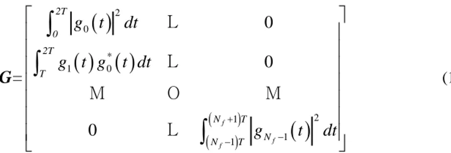
where △V is an nL×Nf matrix, G is an Nf×Nf matrix defined as
( )
( ) ( )
( )
( ) ( ) 2 0 1 0 2 1 1 1 0 0 0 f f f 2T 0 2T * T N T N N T g t dt g t g t dt = g t dt + − −
G L L M O M L (14)It is clear that Cs is a positive definite Hermitian matrix, therefore Cs takes the form of
UΛUH, whereU is a unitary matrix, and the diagonal elements of Λ should be positive. We assume that the coefficients of quasi-static Rayleigh fading are zero mean and 0.5 variance per dimension. Hence, the rows of U are a set of orthogonal eigenvectors. Since unitary matrix should not change statistical character of H. In addition, Q function can be simplified as Q(x)≤(1/2)exp(-x2/2) [28]. Then (7) is upper-bounded as
(
)
rank( ) 2 1 1 ( ) 1 ( ) 2 2 R R R N Cs i i n i n p exp
= = → ˆ
−
, D D | H / (15)Where λi is defined as the eigenvalues of Cs, as the magnitude of βi,nR , i.e. |βi,nR |, is Rayleigh distributed, ρ= |βi,nR |2 is exponentially distributed. Then (15) is further derived into
(
)
0 rank( ) 1 1 rank( ) 1 1 2 ( ) ( ) ( ) 2 (1 ) 2 R R R N Cs i i n N Cs i i p exp
exp
d
= = − = → − − +
ˆ D D / (16)For MA scheme in TWRM system, the outage probability can be evaluated as
(
)
(
)
R
out 1 r SA SB th r SA SB th
P = −P max
,
−P min
,
(17)where γSA denotes the SNR of node A to node R, and γSB denotes the SNR of node B to node R. γth denotes the threshold SNR.
3.2 The algorithm of Antenna Selection
Since HA and HB share common antennas at relay node R in MAC scheme, it shall bring us a challenge to exploit joint transmit antenna selection and receive antenna selection (JTRAS) at A, B, and R. Hence in this section, we investigate five cases of antenna selection. For the last case, our algorithm of JTRAS is proposed to approach optimal performance. As illustrated in Fig. 1, 1≤ nA ≤NA, and 1≤ nB ≤NB, nL =nA+nB, 1≤ nR ≤NR
1) TAS at node A
In this case, 1≤ nA <NA, nB=NB, thus nL =nA+NB. Then the channel for MA is given as
1 1 1 1 1 1 N 1 1 N (a) (a) (B) (B) (a) (a) (B) (B) R L nA B NR NRnA NR NR B N n Bh
h
h
h
h
h
h
h
=
=
, , , , , , , , aH
H
H
L
L
M O
M
M O
M
L
L
(18)Since there are |Θ|=CNAnA subsets in all, optimal TAS is to find the optimal subset
according to selection criterion. In this paper, we employ (19) as the criterion that yields the biggest SNR from all possible subsets [29].
a 1 0 SNR a a H H − = s H A E n N (19) 2) TAS at node B
1 1 1 1 1 1 1 1 b (A) (A) (b) (b) (A) (A) (b) (b) R L NA nB NR NRNA NR NRnB N nh
h
h
h
h
h
h
h
=
=
, , , , , , , , AH
H
H
L
L
M O
M
M O
M
L
L
(20)Since there are |Θ|=CNBnB subsets in all, optimal TAS is to find the optimal subset
according to selection criterion. In this paper, we employ (21) as the criterion that yields the biggest SNR from all possible subsets.
b 1 0 b b SNR H H − = s H B E n N (21)
3) TAS at both A and B
In this case, 1≤ nA <NA, 1≤nB<NB, thus nL = nA +nB. Then the channel for MA is given as
1 1 1 1 1 1 1 1 b (a) (a) (b) (b) (a) (a) (b) (b) R L nA nB NR NRnA NR NRnB N nh
h
h
h
h
h
h
h
=
=
, , , , , , , , aH
H
H
L
L
M O
M
M O
M
L
L
(22)Since there are |Θ|= CNAnA× CNBnB subsets in all, optimal TAS is to find the optimal subset
according to selection criterion. In this paper, we employ (19) and (21) as the criteria that yield the biggest SNR from all possible subsets.
4) RAS at node R
In this case, 1≤ nR <NR, and NL = NA +NB. Then the channel for MA is given as
1 1 1 1 1 1 1 1 A B (A) (A) (B) (B) (A) (A) (B) (B) R L NA NB nR nRNA nR nRNB n Nh
h
h
h
h
h
h
h
=
=
, , , , , , , ,H
H
H
L
L
M O
M
M O
M
L
L
(23)Since there are |Θ|= CNRnR subsets in all, optimal TAS is to find the optimal subset
according to selection criterion. In this paper, we employ (24) as the criterion that yields the biggest SNR from all possible subsets.
r H H 1 0 A A B B SNR H H +H H − = s L E n N (24) 5) AS at both A, B and R
In this case, 1≤ nA <NA, 1≤nB<NB, and 1≤ nR<NR. Then the channel for MA is given as
1 1 1, 1 1 1, ,1 ,1 b (a) (a) (b) (b) (a) (a) (b) (b) R L nA nB nR nR,nA nR nR,nB n nh
h
h
h
h
h
h
h
=
=
, , aH
H
H
L
L
M O
M
M O
M
L
L
(25)Since there are |Θ|= CNRnR× CNAnA× CNBnB subsets in all, optimal TAS is to find the
optimal subset according to selection criterion. As the number of total antennas grows, however, it is unbearable to employ exhaustive search algorithm. As shown in Table 2, we employ the proposed algorithm for AS at both A, B and R in the system.
Table 2. Proposed algorithm for AS at both A,B and R
Procedure Operations
Input: The matrices of channel state information for HA and HB
Steps 1: H=[ HCalculate the eigenvalues of HHA HB]; H so as to get {λ1,…, λNR};
Steps 2:
Sort them as 1 NR
' '
, from which we choose the largest nr eigenvalues and
find the position indices corresponding to { 1 nR
' '
, ,
}. Then we define SR={ ( )1 ( )nR
r r
i , ,i } as the AS set at relay R.
Steps 3: Then, we obtain ’ NA
A C
H n ×R
and ’ R NB
B C H n × ;
Steps 4: For both HA’ and HB’, we employ decreased JTRAS in Ref. [30].
Output: In the end,
b
R L
nn = a
H H H is obtained.
As the complexity for the multiplication of two nR× nR matrices is О(nR3), the complexity
for exhaustive search algorithm can be calculated into
(
)
(
)
(
)
2 Exhaustive Cpl R A B R R R A A A B B B N ! N ! N ! n N n ! n ! N n ! n ! N n ! = − − − (26) For the proposed algorithm, the complexity for each step in Table 2 is given as follows:Step 1: 2
(
)
R A B R
Step 2 and 3: 2 R N Step 4:
(
)
3 3 3 3 3 3 4 4 4 4 4 2 4 6 A R R A B R R B A A B B R A A B B N n n N N n n N N n N n n N −n +N −n + + + + − + + (27) For step 4, the exact calculation can be found in [30], then the complexity for the proposed algorithm can be expressed as(
)
(
)
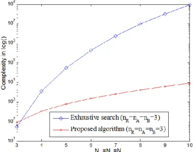
2 2 4 4 4 4 oposed 3 3 3 3 3 3 4 Cpl 4 2 6 A A B B Pr R A B R R A R R A B R R B A A B B R N n N n N N N N N N n n N N n n N N n N n n − + − = + + + + + + + − + + + 3 (28)For the convenience of comparison, it is assumed in (26) and (28) that nR=nA=nB and NR=NA=NB. It can be shown in Fig. 2 that, as the total number increases, the proposed
algorithm will provide drastically lower complexity than exhaustive search algorithm.
Fig. 2. The evaluation of complexity in logarithm for the two algorithms
4. Simulations and Discussions
In this section, we present both numerical and Monte Carlo simulation for TWRM system with CPM. In each simulation, the simulation setup is made according to Table 3. To evaluate the performance of TWRM system with CPM, we would like to present some examples with various antenna setting (nA/NA, nR/NR, nB/NB) for nodes A, R and B.
Table 3. Simulation setup Parameters value CPM format LRET L 1 hp 1/2 M 2 Nf 130
Spatial channel independently Rayleigh fading
NA the number of total antennas at terminal node A
nA the number of selected antennas at terminal node A
NR the number of total antennas at relay node R
nR the number of selected antennas at relay node R
NB the number of total antennas at terminal node B
nB the number of selected antennas at terminal node B
Fig. 3 depicts the frame error rate versus the SNR in decibel without TAS in TWRM system with CPM. The figure suggests that as the number of antennas at terminal node A is increased, the performance will improve 2 dB or so. The same conclusion is likewise suitable for node B.
Fig. 3. Frame error rate vs. SNR in dB without TAS in TWRM system with CPM
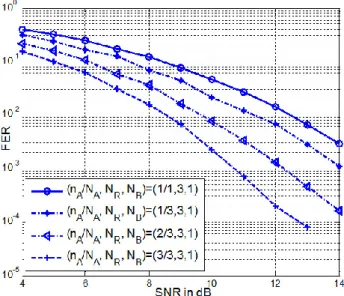
The frame error rate of TAS in TWRM system with CPM is shown in Fig. 4, in which the antenna setting is (nA/NA, NR, NB). If (NA, NR, NB) remains invariable and nA increases from 1 to 3, the performances will improve greatly. Especially in high SNR, the performance can provide 1–2 dB gain, which is determined by the transmit diversity and selection gain.
Fig. 4. Frame error rate vs. SNR in dB with variable selected antennas at terminal node A Fig. 5 presents the performance of TAS in TWRM system with CPM, in which (nA, NR, NB)
is fixed and NA varies from 1 to 3. The overall performances of TAS in Fig. 5 are not as
distinct as those in Fig. 4, albeit the effect of TAS can still be observed clearly. In particular, the results further demonstrate that the performances of TAS at both terminals A and B will improve more than those with TAS at one terminal alone.
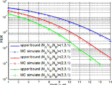
Fig. 5. Frame error rate vs. SNR in dB with variable available antennas at terminal node A Fig. 6 illustrates the performance of RAS in TWRM system with CPM, in which the antenna setting is (NA, nR/NR, NB), and the number of selected antennas at relay node R varies from 1 to 3. If (NA, NR, NB) remains invariable and nR increases from 1 to 3, the performances will improve greatly. Especially in high SNR, the performance can provide more than 2 dB gain, which is attributed to the receive diversity and selection gain.
Fig. 6. Frame error rate vs. SNR in dB with variable selected antennas at relay node R
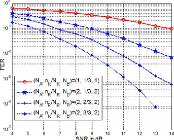
Fig. 7 illustrates the performance of antenna selection at both A, B, and R in TWRM system with CPM, in which the antenna setting is (nA/NA, nR/NR, nB/NB). It is shown that the scheme of (1/2, 1/3, 1/2) can provide 4 dB gain compared to that of (1, 1/3, 1). It is inferred that the antenna selection at both A and B can obtain the selection gain. Further, as the antennas at node R are exploited fully, the FER performance can be improved more apparently with diversity gain.
Fig. 7. Frame error rate vs. SNR in dB with variable selected antennas at terminal node A, B and relay node R
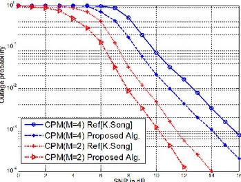
Fig. 8 illustrates the outage probability for CPM with M=2 and 4 compared between two algorithms. It is shown that the scheme of CPM with M=2 has better outage probability than that of CPM with M=4. Meanwhile, it is shown that the proposed algorithm of antenna selection has better outage probability than that of Min-max [31] antenna selection for
Fig. 8. The outage probability for CPM with M=2 and 4 compared between two algorithms
5. Conclusion
In the paper, we have reduced the complexity of decoding by simplifying the joint states of CPM in two-way relaying MIMO systems. Additionally,the tight upper-bound of frame error rate is obtained for CPM in TWRM systems. Finally, the error performances for various schemes are simulated and compared with the analysis in this paper. It is worth noting that this study is limited to single user system. In future, we would like to investigate CPM modulation with multi-users in two-way relaying MIMO systems.
References
[1] R. Ahlswede, N. Cai, S. R. Li, and R. W. Yeung, “Network information flow,” IEEE Transactions
on Information Theory, vol. 46, no. 4, pp. 1204-1216, 2000. Article (CrossRef Link)
[2] Z. Li, M. Xu, T. Liu, and L. Yu, “A network coding-based braided multipath routing protocol for wireless sensor networks,” Wireless Communications and Mobile Computing, vol. 2019, pp. 1-25, 2019. Article (CrossRef Link)
[3] S. Katti, S. Gollakota, D. Katabi, “Embracing wireless interference:analogy network coding,”
ACM SIGCOMM Computer Communication Review, vol. 37, no. 4, pp. 397-408, 2007.
Article (CrossRef Link)
[4] T. Koike-Akino, P. Popovski, and V. Tarokh, “Optimized constellations for two-way wireless relaying with physical network coding,” IEEE Journal on Selected Areas in Communications, vol. 27, no. 5, pp. 773-787, 2009. Article (CrossRef Link)
[5] S. Fu, K. Lu, Y. Qian, and H. Chen, “Cooperative wireless networks based on physical layer network coding,” IEEE Wireless Communication Magazine, vol. 17, no. 6, pp. 86-95, 2010.
Article (CrossRef Link)
[6] M. C. Ju and I. M. Kim, “Error performance analysis of BPSK modulation in physical-layer network coded bidirection relay networks,” IEEE Transactions on Communications, vol. 58, no. 10, pp. 2770-2775, 2010. Article (CrossRef Link)
[7] H. J. Yang, Y. Choi, and J. Chun, “Modified high-order PAMs for binary coded physical-layer network coding,” IEEE Communications Letters, vol. 14, no. 8, pp. 689-691, 2010.
[8] M. Noori and M. Ardakani, “On symbol mapping for binary physical-layer network coding with PSK modulation,” IEEE Transactions on Wireless Communications, pp. 11, no. 1, pp. 21-26, 2012.
Article (CrossRef Link)
[9] R. Y. Chang, S. Lin, and W. Chung, “Symbol and bit mapping optimization for physical-layer network coding with pulse amplitude modulation,” IEEE Transactions on Wireless
Communications, vol. 12, no. 8, pp. 3956-3967, 2013. Article (CrossRef Link)
[10] V. Namboodiri, K. Venugopal, and B. S. Rajan, “Physical layer network coding for two-way relaying with QAM,” IEEE Transactions on wireless communications, vol. 12, no. 10, pp. 5074-5086, 2013. Article (CrossRef Link)
[11] V. T. Muralidharan, V. Namboodiri, and B. S. Rajan, “Wireless network-coded bidirectional relaying using latin squares for M-PSK modulation,” IEEE Transactions on Information Theory, vol. 59, no. 10, pp. 6683-6711, 2013. Article (CrossRef Link)
[12] Q. Y. Yu, D. Y. Zhang, H. H. Chen, and W. X. Meng, “Physical layer network coding systems with MFSK modulation,” IEEE Transactions on Vehicular Technology, vol. 65, no. 1, pp. 204-213, 2016. Article (CrossRef Link)
[13] N. Sha, Y. Y. Gao, X. X. Yi, W. Li, and W. Yang, “Joint CPFSK Modulation and Physical-Layer Network Coding in Two-Way Relay Channels,” IEICE Transactions on Fundamentals of
Electronics Communications and Computer Sciences, vol. E97A, no. 4, pp. 1021-1023, 2014.
Article (CrossRef Link)
[14] S. Zhang and S. C. Liew, “Physical layer network coding with multiple antennas,” in Proc. of
IEEE Wireless Communication and Networking Conference, pp.1-6, 2010.
Article (CrossRef Link)
[15] K. A. Toshiaki, “Adaptive network coding in two-way relaying MIMO systems,” GlobeCom 2010, pp. 1-9. 2010. Article (CrossRef Link)
[16] T. M. Vijayvaradharaj and B. S. Rajan, “Wireless network coding for MIMO two-way relaying,”
IEEE Transactions on Wireless Communications, vol. 12, no. 7, pp. 3566-3577, 2013.
Article (CrossRef Link)
[17] K. Yang, N. Yang, C. Xing, J. Wu, and Z. Zhang, “Space-Time Network Coding With Transmit Antenna Selection and Maximal-Ratio Combining,” IEEE Transactions on Wireless Communications, vol. 14, no. 4, pp. 3566-3577, 2015. Article (CrossRef Link)
[18] W. C. Liu, “Performance Analysis of Relay Selection with Enhanced Dynamic Decode-and-Forward and Network Coding in Two-Way Relay Channels,” Wireless Personal
Communication, vol. 109, pp. 909-944, 2019. Article (CrossRef Link)
[19] V. Kumar, B. Cardiff, and M. F. Flanagan, “User-Antenna Selection for Physical-Layer Network Coding Based on Euclidean Distance,” IEEE Transactions on communications, vol. 67, no. 5, pp. 3363-3375, 2019. Article (CrossRef Link)
[20] T. Aulin and C. Sundberg, “Continuous phase modulation-Part I:Full response signalling,” IEEE
Transactions on Communications, vol. 29, no. 3, pp. 196-209, 1981. Article (CrossRef Link)
[21] R. L. Maw and D. P. Taylor, “Space-Time Coded Systems using Continuous Phase Modulation,”
IEEE Transactions on Communication, vol. 55, no. 11, pp. 2047-2051, 2007.
Article (CrossRef Link)
[22] R. Mesleh, M. D. Renzo, H. Haas, and P. M. Grant, “Trellis Coded spatial modulation,” IEEE
Transactions on Wireless Communication, vol. 9, no. 7, pp. 2349-2361, 2010 .
Article (CrossRef Link)
[23] E. Basar, U. Aygolu, E. Panayirci, and H. V. Poor, “New Trellis Code Design for Spatial Modulation,” IEEE Transactions on wireless communication, vol. 10, no. 8, pp. 2670-2680, 2011.
Article (CrossRef Link)
[24] X. Zhang and M. P . Fitz, “Space-Time Code Design With Continuous Phase Modulation,” IEEE
Journal on Selected Areas in Communications, vol. 21, no. 5, pp. 783-792, 2003.
Article (CrossRef Link)
[25] A. G. Zajic and G. L. Stüber, “A Space Time Code Design for Partial Response CPM: Diversity Order and Coding Gain,” in Proc. of IEEE International Conference on Communication, pp. 719-724, June 2007. Article (CrossRef Link)
[26] P. A. Laurent, “Exact and approximate construction of digital phase modulation by superposition of amplitude modulated pulses,” IEEE Transactions on Communication, vol. 34, no. 2, pp. 150-160, 1986. Article (CrossRef Link)
[27] U. Mengali and M. Morelli, “Decomposition of M-ary CPM Signals into PAM Waveforms,”
IEEE Transactions on Information Theory, vol. 41, no. 5, pp. 1265-1275, 1995.
Article (CrossRef Link)
[28] J.G. Proakis, Digital Communications, 4th Edition, New York, USA: McGraw-Hill, 2000. [29] R. W. Heath, S. Sandhu, and A. Paulraj, “Antenna selection for spatial multiplexing systems with
linear receivers,” IEEE Communications Letters, vol. 5, no. 4, pp. 142-144, 2001.
Article (CrossRef Link)
[30] G. W. Lei, Y. A. Liu, and X. F. Xiao, “Analysis of joint transmit and receive antenna selection in CPM MIMO systems,” KSII Transactions on Internet and Information Systems, vol. 11, no. 3, pp. 1425-1440, 2017. Article (CrossRef Link)
[31] K. Song, B. Ji, Y. Huang, M. Xiao, and L. Yang, “Performance Analysis of Antenna Selection in Two-Way Relay Networks,” IEEE Transactions on Signal Processing, vol. 63, no. 10, pp. 2520-2532, 2015. Article (CrossRef LInk)
Guowei Lei received the B.S., M.S., and Ph.D degree from Gannan Normal University, Xiamen University, and Beijing University of Posts and Telecommunications in 1999, 2004, and 2019 respectively. His research interests include modulation and codes, space-time codes and MIMO systems.
Hanlan Chen received the B.S., M.S., and Ph.D degree from Fuzhou University, Xiamen University in 1999, 2007 and 2020 respectively. Her research interests include signal processing, modulation and codes, and underwater acoustic communications.
Yuan-An Liu received the B.S., M.S. and Ph.D. degree from University of Electronic Science and Technology, Chendu, China, in 1984, 1989, 1992 respectively. From 1992, he has been with Beijing University of Posts and Telecommunications as professor. His research interests include broadband mobile communication technology, RF and microwave devices, mobile terminals and internet of things.