ICCAS2005 June 2-5, KINTEX, Gyeonggi-Do, Korea
The Design of an Intelligent Assembly Robot System for Lens Modules of Phone Camera.
Jun-Yeob Song*, Chang-Woo Lee* and Yeong-Gyoo Kim
**
* Intelligent Machine Systems Research Center, KIMM, Daejeon, Korea (Tel : +82-42-868-7144/7146; E-mail: [email protected]) **Yoosung Precision Co.,Ltd, Changwon-City, Gyeongnam, Korea
(Tel : +82-55-252-7930; E-mail: [email protected])
Abstract: The camera cellular phone has a large portion of cellular phone market in recent year. The variety of a customer demand makes a fast model change and the spatial resolution is changed from VGA to multi-mega pixel. The 1.3 mega pixel (MP) camera cellular phone was first released into the Korean market in October 2003. The major cellular phone companies released a 2MP camera cellular phone that supports zoom function and a 2MP camera cellular phone is settled down with the Korea cellular phone market. It makes a keen competition in price and demands automation for phone camera module. There is an increasing requirement for the automatic assembly to correspond to a fast model change. The hard automation techniques that rely on dedicated manufacturing system are too inflexible to meet this requirement.
Therefore in this study, this system is designed with the flexibility concept in order to cope with phone camera module change. The system has a same platform that has X-Y-Z motion or X-Z motion with ㎛ order accuracy. It has a special gripper according to the type of a component to be put together. If the camera model changes, the gripper may be updated to fit for the camera module. The controller of this system acquires the data sets that have the information about the assembly part by the tray. This information is obtained ahead of an inspection step. The controller excludes an inferior part to be assembled by using this information to diminish the inferior goods. The assembly jig used in this system has a function of self adjustment that reduces the tact time and also diminish the inferior goods. Finally, the intelligent assembly system for phone camera module will be designed to get a flexibility to meet model change and a high productivity with a high reliability.
1. INTRODUCTION
According to development trend of mobile communication system, in prospect the cellular phone is developed into the compound function terminal that can use communicates, a computer, an AV function smoothly. The multimedia acceleration makes the cellular phone a variety and an upgrade. Market share of the camera cellular phone is expanded according to this demand day by day in a cellular phone market. Table 1 shows that the market share of camera cellular phone was 14.6% in 2003 and it is expecting that it holds a more than 75% in cellular phone in the world in 2007.
Table 1 The world market trend of the cellular phone and the camera cellular phone.
(Unit: million sets, %) 2003 2004 2005 2006 2007 Cellular Phone 432 478 521 562 618 Rate of Increase - 10.6% 9.0% 7.87% 9.96% Camera Cellular Phone 63 135 266 365 464 Market Share 14.6% 28.3% 51% 65% 75% It was factors of spread of initial camera cellular phone to transmit the message, which included a picture to PC or a mobile terminal. This camera cellular phone is sensitive to the fashion in particular, and technical development is very fast, therefore the model change period is very short. A new model
is released in a period almost 6 months after the 110,000 pixels camera cellular phone with 256 colors was released by Sharp in Japan in November 2000. The Samsung Electronics released the 1.3MP camera cellular phone in 2003 and Curitel also released it at a similar time whit Samsung. LG Electronics released a 2MP camera cellular phone equipped with MP3P. 1.3MP and 2MP camera module are necessary to take picture of photo quality. The 3MP camera cellular phone was released at the end of year, 2004 and Samsung Electronics release a 7MP camera cellular phone with a zoom function at present. The camera cellular phone will provide more various functions by compunction security by face recognition not to mention compunction message delivery with a picture in a future ubiquitous society. The camera cellular phone is becoming a multimedia platform in ubiquitous society. A camera module is improving while maintaining small size and low cost therefore the mass production system is needed in camera module industry.
Keywords: cellular phone, camera module, mega pixel, self adjustment, assembly system
2. NECESSARY OF AUTOMATION IN
CAMERA MODULE PRODUCTION
It seems to be a lot of the camera cellular phone is released at the same time in a market as one model has developed. Therefore mass production system is necessary in the camera module industry. The MP camera module is used in earnest at present, but it cannot be supplied like demand because there is a lot of problem in core parts supply because of lack of a capacity in technology development and a mass production system is not established. The core part supply problem will be solved in the near future, but there is a difficulty in mass production because the most camera module production companies have depended on a manual work. Because labor costs are high and many companies have a difficulty in a manpower supply in Korea, they have a plan to move a production line to China where labor costs are cheap.ICCAS2005 June 2-5, KINTEX, Gyeonggi-Do, Korea
The pollution by particles is one of the major causes that make inferior good. Human is main source of pollution therefore the production system which depended on manual work has a relative high rate of inferior good and has to demand a wide clean room. The clean booth that can make special space clean is established hard for a manual production system. The wide clean room raises the unit cost of production. Fig. 1 shows one of the inferior goods by pollution. For this reason the demand of automation is growing larger in camera module production.
Fig. 1 Photo of lens defect
3. NECESSARY CONDITION OF AUTOMATION
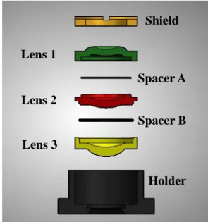
It demands the fast model change that the customer of camera cellular phone is very sensitive to the fashion and is developed quickly in technology. The Lens module in VGA class has five parts but as shown in Fig. 2 the lens module in MP class has three lenses, two spacers, one shield and one holder.Fig. 2 Lens module of camera cellular phone in MP class As above mentioned cellular phone companies have released a new model in a period almost 6 months. For the early stage one lens is made from glass and the other parts are made by plastic injection molding but all parts are made by
there is an increasing requirement for the camera module assembly to respond to fast model change. The camera module assembly system has to be reconfigurable system that will allow flexibility and change the system itself. This system is designed for rapid adjustment of new model by the easy change of its component such as a gripper or pick-and-place system in order to reduce the ramp-up time. It has to be designed in open-architecture control and in modular machines that can be rearranged or replaced quickly and reliably. The modular machine is controlled and tested separately so that must secure certain reliability. This assembly system can reduce the cost of equipment modification because the system components can be quickly redesigned to meet the camera module change. The Assembly accuracy is required under 5 ㎛ and the outside of holder which is a reference of a gripper or pick-and-place system was not accurate, so that the only use of a gripper or pick-and-place system has a difficulty to meet the accuracy. In order to solve this problem, some company made the lens module assembly system that used vision system in alignment. But it increases the ramp-up time and the cost of equipment modification that in general the vision system needs case-by-case study. The vision system must stop in order to get a good image so that tact time gets longer and the productivity drops. The installation of a vision system that includes a lot of components complicates compact design and raises the cost of equipment. For that reason, this paper proposed three types of a self adjustment module which uses compressed air. It is explained in the following in detail.
Shield
Lens 1
Spacer A
Lens 2
Spacer B
Lens 3
Holder
Fig. 3 Cluster type assembly system
ig. 3 shows the cluster type assembly system that pr
4. SELF ADJUSTMENT MODULE
he holder inside becomes a reference, and one after an
F
oposed it in this paper. As shown in Fig. 3, the total assembly system is designed in modular machines that is controlled and tested separately. It makes the cost of a clean booth installation down that the cluster type is excellent in space utilization. The clean booth helps inferior goods by pollution reduce and the productivity increases.
T
other are assembled Lenses, spacers and shield. The holder plastic injection molding in MP class at present. Like this
ICCAS2005 June 2-5, KINTEX, Gyeonggi-Do, Korea
is situated at an assembly position by a gripper with a mechanical error. Next the gripper picks up a first lens and moves to the assembly position and then assembles a holder and lens with an alignment error. The total alignment error includes parts self-error and gripping error and is inevitable. As above mentioned some company tried to solve this problem by using vision system. But this paper introduces new method by using self adjustment module that can make the parts assembled with reference to the holder inside. The self adjustment module must be small size to meet easy model change and have a long life time.
4. pe
he ball is putted on one plane and then the other plane is pu
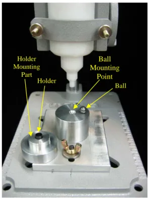
Fig. 4 Type 1 Self adjustment module using a ball
s sh to
m
4. pe 2 : Air bearing supporting
he main function that the self adjustment module must ha
1 Ty 1 : Single point supporting by using a ball T
tted on the ball. Though there is a friction, the two planes are moved by a ball rolling motion relatively. The ball rolling motion is so very smooth that a small force can move the plane in X, Y axis. The single ball rolling motion allows tilt motion that also compensate alignment tilt error between the holder and the other parts.
A own in Fig. 4 the ball mounting point is designed ove within ± 100 ㎛ and this range is considered as maximum mechanical error. The mass of holder mounting part has to be light in order to move smoothly. We will change the holder mounting part in order to reduce the mass. The holder mounting part merely is modified to cope with camera module change. This module has so stiffness in Z axis that excessive assembly force makes a holder and the other parts damaged. The assembly system must have a mechanism absorbing the excessive assembly force such as a spring.
2 Ty T
ve is to move smoothly in X, Y direction. The air bearing is
mechanical element to satisfy this demand sufficiently
Porous Air
Bearing
Fig. 5 Type 2 Self adjustment module using air bearing here are several types of the air bearing and among them, an
4. pe 3 : Air chamber supporting
he holder mounting part floats up into compressed air in th
T
orifice type is common. If the supported mass is light, it makes stability low that the supporting force of an orifice type focuses on very small area. The mass of holder mounting part has to be light in order to move smoothly. For that reason, the porous type air bearing is selected even though the price of it is expensive relatively. The supporting force of a porous air bearing is distributed over the whole area. The porous air bearing type has also stiffness in Z axis and permits to move in X, Y axis without mechanical contact. Therefore this type must also have a mechanism absorbing the excessive assembly force. The porous air bearing type do not allows tilt motion. The mechanism absorbing the excessive force is designed to compensate the alignment tilt error. This mechanism compensating tilt error can be realized easily by using a spring.
3 Ty T
is type. The compressed air is supplied into the chamber and diffused. The porous filter helps to make the pressure of a chamber uniform. Holder Mounting Part Holder Ball Holder Mounting Part
Ball
Mounting
Point
Holder Mounting PartFig. 6 Type 3 Self adjustment module using air chamber
ICCAS2005 June 2-5, KINTEX, Gyeonggi-Do, Korea
A pe
5. CONCLUTION
e have researched the trend of a world market of a ce
ept of assembly system can be rearranged or
REFERENCES
]Deutsch Bank,
era for mobile phone,”
[3] and A.G. Ulsoy, “Reconfigurable
[4]
[5]
s shown in Fig. 6, the alignment error is compensated rfectly by this assemble module. Unlike previous two types, this module stiffness is not excessive and fixed in Z axis. The stiffness is defined by the supplied pressure and area of base plane of the holder mounting part. And the stiffness is equal to the assembly force. Therefore the assembly force is controlled by an air pressure. It makes pre-alignment that the shape of the holder mounting part is cone type.
W
llular phone and camera cellular phone. In word market of cellular phone the market share of camera cellular phone grow larger quickly.
The design conc
replaced quickly and reliably to cope with a fast model change. We propose the self adjustment module that can be moved without friction by using an air bearing and a ball. These modules have stiffness in Z axis and can be moved smoothly in X, Y axis. Therefore while the parts are assembled, the alignment error between a holder and other part can be compensated. These modules can reduce the tact time and improve productivity. These modules are designed to cope with the model change by the modification of a holder mounting part and a gripper.
[1 August, 2003. [2] Vern Klein, “Mega pixel cam
IIC-China/ESC-China 2004 Conference Proceedings, pp.
56-58, 2004. Koren, Y.
Manufacturing Systems,” Engineering Research Center
for Reconfigurable Machining Systems (ERC/RMS) Report # 1 The University of Michigan, Ann Arbor 1997.
Koren, Y. Ulsoy, A.G. and Z. Pasek, “Reconfigurable Manufacturing Systems: A New Paradigm,” to appear in
the SAE International Manufacturing Conference, 1997.
Dave Faulkner, Ben Levy, Tim Garner, “Open-Architecture Platforms,” Circuits Assembly, 1999.