Development of a single-channel millimeter-wave interferometer system for electron density
measurement during KSTAR commissioning phase
Y. U. Nam
Korea Basic Science Institute, Yusung, Taejeon 305-333, Korea, [email protected]
1. Introduction
Electron density is a primary parameter in tokamak plasma physics research, and interferometry is a widely used diagnostic tool for the measurement of electron density. Since a source frequency of the interferometer system is determined by a line-integrated density of plasma, systems of different types will be prepared for each operation phase of Korea Superconducting Tokamak Advanced Research (KSTAR). A vertical and tangential interferometry/polarimetry system using far infrared laser will be installed for main operation phase [1]. For commissioning phase of KSTAR where peak electron density of 1019 m-3 and plasma radius of 30 cm are expected [2], a single-channel millimeter-wave system will be installed. A simple and low cost design is the most important point on the development of this system, which will be used for the commissioning phase only.
2. System Description
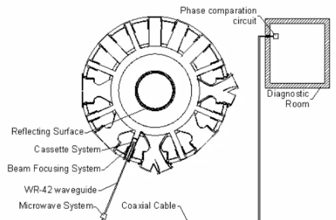
Due to a cryostat for the cryogenically cooled superconducting coils, the entrant ports to the vacuum vessel are far from the plasma boundary in KSTAR. A retractable cassette system was designed for deep positioning of the diagnostic system [3]. Since construction plans altered that inner tiles and neutral beam injection (NBI) armors are not installed in the commissioning phase, some system designs have been adjusted for that purpose. Figure 1 shows a schematic diagram of the system.
Figure 1. Schematic diagram of the KSTAR millimeter-wave interferometer system.
2.1 Cassette System
Although a reflecting concave mirror cannot be provided on the inner wall of vacuum chamber, the cassette system will be still placed in a horizontal port. It is also possible that adopting an interferometer system of Mach-Zehnder type using vertical ports, but it is not favorable because of long transmission length and narrow port geometry. Instead of carbon tile, chamber wall itself made of stainless steel will be used as the reflecting mirror. Beam reflection capability of stainless steel is not poor compare with carbon, but its cylindrically convex surface will deteriorate beam focusing condition. Beam focusing system has been designed as a separate module from the cassette and will be combined using a linear rail system for the convenience of maintenance and performance upgrade. Mirror tilting mounts with pneumatic remote controller have been adopted for more accurate alignment.
Although the interferometer system should be removed after commissioning phase, design of the cassette has been performed considering further use. Other microwave diagnostics system such as a reflectometer, microwave imaging reflectometer, or electron cyclotron emission imaging are planed to be installed during the main operation phase. Most of these systems need a window on center position when the interferometry system needs two symmetrical windows near center position. Satisfying both conditions, an additional adapting flange is inserted for the vacuum windows. Using the adapting flange and the linear rail system, most types of diagnostics can be installed during the main operation phase without serious modification of cassette design. Depth of cassette has been also determined considering position of the NBI armor although the armor is not installed during commissioning phase.
2.2 Microwave System
Microwave parts such as oscillators and mixers will be placed 10 m off from tokamak to prevent damage from intense magnetic field. WR-42 oversized rectangular waveguides are adopted as a wave transmitting system considering both cost and power loss efficiency. Total power loss of the waveguide system will be about 10 dB. Corrugated waveguide system shows much better power efficiency, but it is too expensive for temporary used diagnostics system. Transactions of the Korean Nuclear Society Autumn Meeting
Figure 2. 280 GHz microwave parts module.
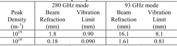
Fiqure 2 shows a microwave parts module. In the previous paper [3], source frequency was decided as 280 GHz. Since Gunn diode oscillator of that frequency is commercially not available, 93 GHz oscillators with frequency triplers have been used as a beam sources. Output beam power of oscillator is 30 mW and efficiency of tripler is 10%. This microwave system can be easily converted to 93 GHz system by removing triplers and changing mixers. 93 GHz operation mode can provide much higher power but beam refraction due to plasma density gradient can be a serious problem. This mode will be favorable when the electron density during commissioning phase is lower than expected. The performance of 280 GHz mode and 93 GHz mode are compared in Table 1 where the peak electron density of 1019 m-3 and 1018 m-3. In Table 1, beam refraction means beam position deviation due to plasma at the inner wall, and vibration limit means acceptable path length variation due to vibration for the fringe resolution of 1/10. 93 GHz mode will be also useful during beam alignment procedure without plasma.
Table 1. Performance comparison of interferometer system with different source frequency mode.
280 GHz mode 93 GHz mode Peak Density (m-3) Beam Refraction (mm) Vibration Limit (mm) Beam Refraction (mm) Vibration Limit (mm) 1019 1.8 0.90 16.1 8.1 1018 0.18 0.090 1.61 0.81
2.3 Phase Comparator Circuit
100 MHz intermediate frequency (IF) signals from microwave mixers are transmitted using coaxial cable to a diagnostics room. Total length of coaxial cable is about 25 m. These signals are down-converted to 5 MHz to fit frequency with operation range of phase comparator circuit. Before compare the phases of two signals, a counting circuit is provided for a multi-fringe counting. With this circuit, the phase variation of maximum 16 fringes can be measured without fringe jumps. Although a phase resolution is deteriorated proportional to the multi-fringe counting capability, these problem can be compensated by simultaneously measuring the single-fringe counting mode and
multi-fringe counting mode. The phase resolution of 1/10 fringe can be provided with the multi-fringe counting capability of 16 fringes. Final output signals of the phase comparator circuit are DC voltage signal of 0 ~ 5 V, which are collected and are analyzed by main data acquisition system of KSTAR.
3. Conclusion
A single-channel millimeter-wave interferometer system has been developed for the measurement of electron density during commissioning phase of KSTAR. To construct simple and low cost diagnostics tool with limited environmental condition of commissioning phase of KSTAR, some design of the cassette and the microwave system have been modified. This system can be measure the line-integrated electron density on KSTAR commissioning phase, where the peak density of 1018 ~ 1019 m-3, with the phase resolution of 1/10 fringe.
REFERENCES
[1] M. S. Cheon, Y. U. Nam, J. H. Ha, and Y. S. Hwang, Design of a far-infrared interferometer/polarimeter system for Korea Superconducting Tokamak Advanced Research, Review of Scientific Instruments, Vol. 75, p.3402 , 2004 [2] Jayhyun Kim, Jin Yong Kim, Hogun Jhang, Wonho Choe, Young-Soon Bae, Moo Hyun Cho, and Won Namkung, Development of feasible breakdown and initial start-up scenarios for the KSTAR commissioning phase, 5th General Scientific Assembly of Asia Plasma & Fusion Association, 2005.
[3] Y. U. Nam, M. S. Cheon, M. Kwon and Y. S. Hwang, Design of a single-channel millimeter-wave interferometer system for Korea Superconducting Tokamak Advanced Research, Review of Scientific Instruments, Vol.74, p.1613, 2003.