A Smooth Position Control of Ultrasonic Motor Using Fuzzy Logic
Jung Hoon Lee1), Hang Bin
Abstract
Ultrasonic motor (USM) is a new type motor which is driven by the ultrasonic vibration of piezoelectric elements. It possess many useful features that electromagnetic motors do not have, such as low speed and high torque. However, ultrasonic motor has heavy nonlinear speed characteristics and is sensitive to the change of drive conditions. In order to solve these problems, we present a smooth position control scheme for ultrasonic motor using fuzzy logic control with human expertise and without the need of any precise mathematical model. A "smooth operation" consideration is included when constructing the fuzzy rule base in order to achieve a most smooth response. An experimental position control system is constructed to show the effectiveness of the proposed control scheme.
Keyword: Ultrasonic Motor, Position Control, Fuzzy Control
I. Introduction
Ultrasonic motors(USM) are newly developed motors with a driving principle different from that of traditional electomagnetic motors. Ultrasonic motors use ultrasonic vibration - a type of elastic vibration - to obtain a driving force, which drives the motor using friction. In 1973, H. V. Barth of IBM proposed a motor driven by ultrasonic vibration[1]. Various mechanism based on virtually the same principle were also proposed by V. V.
Lavrinenko et al. in the USSR[2]. They had pointed out the various features of the ultrasonic motor, I.e.
its simple structure and low cost, the high torque produced at low speed, the large power output per unit weight, the possibility of precise positioning, and because copper wire is not required, the conservation of resource etc. In 1980, T. Sashida in Japan proposed and experimentally fabricated a vibrating - piece type of motor[3]. It was first such motor developed that could satisfy the conditions for practical use. But because the vibrating pieces were
1)Dept of Control & Instrumentation Engineering, Gyeongsang National University, Corresponding Author
Manuscript received
fixed at almost a right angle to the rotor, wear and tear of the contact surface was problem. To solve this problem, T. Sashida proposed and experimentally fabricated another motor in 1982, this time a travelling wave ultrasonic motor[4]. This motor make use of the fact that when a travelling wave propagates along a finite elastic body, the surfaec particles perform an elliptical motion. This invention showed that an ultrasonic motor could be produced if the stator, an elastic body, moved elliptically. USM may be utilized for supplementary purposes, mainly in areas of general application where the electromagnetic motor is inadequate. This is especially to be hoped for in special applications e.g. where the flexibility of choice of the shape is required and the duration of operation is short. As an example, the ring-type USM is already being used as the drive mechanism of the auto-focus lens in cameras by Canon Co. Ltd[5]. A two-sided piezoelectric traveling-wave rotary ultrasonic motor si developed as a high torque-density solid-state actuator for use in the NASA/JPL Mars Micro Lander manipulator arm[6]. Some other application includes head-support system of a VIP seat in limousines[7], and watch devices[8]. They have been proposed for use in nuclear magnetic resonance devices[9] too, due to the fact USM neither produce, nor are affected by magnetic fields.
frequency and applied load torque. In order to implement a USM control system in practice, it is necessary to introduce the dynamic mathematical modeling of USM. But it is extremely difficult to perform this modeling from a theoretical point of view. In recent years, there have been reported some precise mathematical models of USM based on equivalent circuit[10] or Minddlin and Reissner theories[11], however, these models are too complex to apply for motor control.
Therefore, most speed/position controllers for USM have been designed using a proportional and integral(PI) controller[12][13], which might not use mathematical model of the motor. the control algorithm of this controller is simple, and has the advantageous features- wide stability margin and high reliability - when the PI gains are well tuned.
However. the speed characteristics of USM vary with driving conditions, therefore fixed PI gains tuned can not maintain the control performance all the time.
In order to solve the problems and control the USM with high performance, a fuzzy logic controller is employed. The model free feature of fuzzy control is attractive because it allows implementation of the control laws without initially having to develop nonlinear dynamic models or complex control system architecture. Moreover, fuzzy control is robust with respect to plant parameter variations and disturbance torque. This paper presents a position control system for USM, which uses fuzzy logic control. The rule base of the fuzzy logic controller is designed such that the system response is as smooth as possible, I.e. there's no abrupt change in USM speed.
II. Design of a Fuzzy Logic Controller for USM
2.1 Overview
A fuzzy controller design involves incorporating human expertise on how to control a system into a set of rules and use inference mechanism in the fuzzy controller reasons over the information in the knowledge base, the process outputs, and the user-specified goals to decide what inputs to
Figure 1 Block diagram of fuzzy logic controller.
2.2 Fuzzification
The two crisp input variables of the fuzzy controller, the error between current position and commanded position and the speed of USM
, are calculated as following,
(1)
(2)
where is the position set point, the actual position and T the sampling time. Then these two variables are transferred into fuzzy variables with membership functions shown bellow separately.
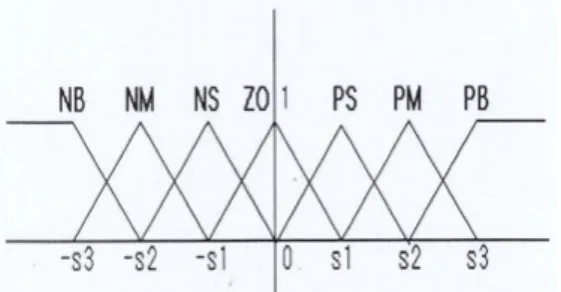
Figure 2 Membership functions for Position Error.
Figure 3 Membership functions for Speed.
Figure 4 Membership functions for Output.
The labels in the above figures are decoded by substituting : negative for N, positive for P, big for B, medium for M, small for S and zero for ZO.
2.3 Rule Base
Fuzzy rule base is the core of a fuzzy system.
Fuzzy rule base are developed heuristically, using intuition and estimates of the motor's states. A
"paper model"[14] is used to visualize the response of the position control system. This model is simply a sketch of desired trajectories from arbitrary starting point to the commanded position. We can draw a sketch of the desired step response of the system with initial position zero like that shown in Fig 5.
Figure 5 A desired trajectory sketch.
Next, several rules in the rule base can be constructed with the help of this sketch. Moreover, in developing the rules, a principle of "smooth operation" is used. That is, we want the speed to change as smooth as possible. Then. with the sketches and design principle, the rules can be generated now. Again use the sketch in Fig. 5,
Figure 6 A trajectory of fuzzy variable change.
suppose at first the motor stopped at position 0, i.e.,
according to
"smooth operation" principle, we may want the motor to accelerate slowly in positive direction, so let , and a rule "IF Error is PB AND Speed is ZO THEN Output is PS" is generated ; In the next sampling cycle, the motor speed becomes , suppose the position error is still , the motor is expected to continue accelerating, so let ; such states changing process continues. Assume the position error is still when the motor speed becomes
. No more desired speed is available now so let
, and the states of the position
control system, of the values
, will stop changing for some time until the position error becomes . Similar states transferring process will repeat until the motor arrives at the commanded position, that is and the Speed is also switched to such that the motor stops at the commanded position. The positioning operation ends. The trajectory of fuzzy variable change in the above discussion is shown in Fig 6.
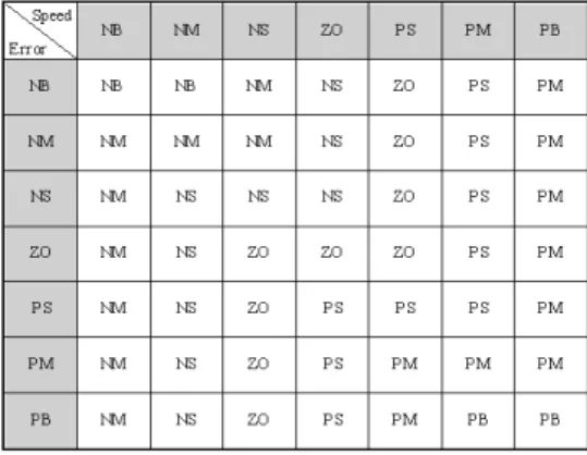
Using the same method, different trajectories of the positioning operation from different initials (for example, and ) can be derived. Thus the entire fuzzy rule base table can be filled in one cell after another. The final fuzzy rule table looks like that in Fig 7.
2.4 Defuzzifier and the complete fuzzy system expression
Use center average defuzzifier, singleton fuzzifier, and product inference engine, the complete fuzzy system[15] is of the form
where is the input to the fuzzy system, and
is the output of the fuzzy system. This form
Figure 7 Fuzzy rule base table.
of the fuzzy system can be implemented conveniently using programming language.
III. The Position Control System and Experimental Results
In this chapter, an experimental position control system for the ultrasonic motor is designed. System block diagram is shown in Fig 8. The following will explain each part of the position control system in detail.
Figure 8 Block diagram of the USM position control system.
3.1 Postion Control System 3.1.1 Control Input Selection
Known from the operation principle of USM, the input to ultrasonic motor are two high frequency sinusoidal signals of different phases. The amplitude,
known as the "control phase", is energized by a voltage which is 90° out of phase with respect to that of the exciting phase. When the phase difference of the driving signals is changed, the travelling wave and the ellipsoidal motion also change, which affect the speed of USM. We choose the frequency method to control the revolution speed of the motor, with the assistance of phase-shift change between to to determine the direction of rotation. Thus the speed of the USM can be changed smoothly from a positive speed to a negative one or vice versa.
3.1.2 System Implementation
The hardware implementation of the position control system is shown in Fig 10. The control console is run on an IBM-PC. The fuzzy algorithm is implemented in this program, as well as displaying, data storage and processing functions, and so on. A 80c196Kc microprocessor is used as the interface between the PC and control hardware such as the variable frequency 4-phase signal generator and the encoder. The 80c196Kc program samples the encoder data, transmit the data to PC through RS232 serial port, receive the fuzzy controller output and transmit it to the variable frequency signal generator which consequently controls the signals determining the motor speed. A rotary encoder is used to measure the angular position of USM. The encoder used is a incremental type, 2000pulses/revolution one with three output phases.
The PC program is programmed in Microsoft Visual C++ on Windows, and the 80c196Kc is programmed with C96.
3.2 Experimental Results
The tested ultrasonic motor is a USR-60 manufactured by Shinsei Co. Ltd. Specifications of the motor are listed in the table bellow.
The ninth flexural vibration mode is excited at a resonance frequency of 39 kHz. In actually, however, the driving frequency is varied from 40 to 43 kHz to control the rotation speed.
Figure 9. Hardware implementation of the position control system.
3.2.1 Step responses
Fig 10. shows the step response of ultrasonic motor position control system using a conventional PI controller. We determine the control input of PI controller as (5) where and are proportional and integral gains
in the PI controller and T is the system sampling time. The step response using PI controller is betterthan the former two, with a setting time of about 6secs. But it is still not fast enough and there's a overshoot.
Table 1 Specifications of a USM
Figure 10 Position control using PI controller.
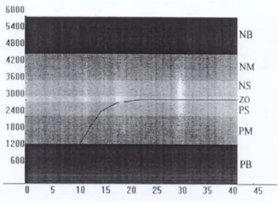
Figure 11 Position control using fuzzy controller.
in the PI controller and T is the system sampling time. The step response using PI controller is betterthan the former two, with a setting time of about 6secs. But it is still not fast enough and there's a overshoot.
Fig. 11 shows the step response using the proposed controller in this paper, the fuzzy logic controller. This fuzzy control system is much faster than conventional controllers, with a setting time of less than 2.5secs. And because of the use of
"smooth operation", the speed changes step by step, causing a rather smooth position curve and no overshoot exists.
3.2.2 Tracking the input signal
Again both the fuzzy controller and the conventional PI controller were used for comparison.
Figure 12 Response to input of postive-negtive value when using PI controller.
Figure 13 Response to input of postive-negtive value when using fuzzy controller.
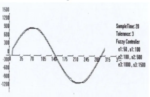
Fig. 14 shows the response to a sinusoidal wave input when using PI controller. Fig. 15 shows the response to a sinusoidal wave input when using fuzzy controller.
Figure 14 Response to a sinusoidal wave input when using PI controller.
Figure 15 Response to a sinusoidal wave input when using fuzzy controller.
IV. Conclusions
In this paper, a fuzzy logic controller with the rule base designed according to a "smooth operation"
principle is designed, since the mathematical model of the ultrasonic motor suitable for practical application has not been developed. The effectiveness of the proposed control scheme is confirmed by experiments. In the step response case, the fuzzy controller shows far better performance over the PI controller. The "smooth operation" design principle works when the speed of USM is changed by the fuzzy controller : each time there's a speed change, the next value is always the nearist one of the current speed. Since there's no abrupt speed change, the position curve is very smooth, no zigzag as shown in the PI controller
but cannot maintain the performance all the way. In the square wave case, the responses of going up and going down are different; in the sinusoidal wave case, the system using PI controller tracks the input well in the increasing part, i.e., when the motor speed is positive, while perform rather worse in decreasing.
References
[1] Barth, H.V.(1973). IBM Technical Disclosure Bulletin,16,2263.
[2] Lavrinenko, V. V., Vishnevski, V. S., and Kartashev, I. K. (1976). Izvestiya Vysshikh Uchebnykh Zavedenii, Radioelektonica, 13,57.
[3] Sashida, T. (1982). Oyo Butsuri, 51, 713-20.
[4] Sashida, T. (1983). Japanese Patent Disclosure 58-148682.
[5] Hosoe, M. (1989). Ultrasonic Technology, 4, (2), 36-41.
[6] McFarland, A. J., Development of a Rotary Ultrasonic Motor for Spacecraft Applications, S.
M. Thesis, Department of Aeronautics and Astronautics, M.I.T., Cambridge, MA, June 1995 [7] Aoyama, M., Hirao, K., Takeda, N., Sagara, S.,
Ohta, H., Kuratsubo, M., 1992. Ultrasonic motor for adjusting the head restraint of automobile seats. Proc. Of the Society of Automotive Engineers of Japan Meeting, pp. 61-64
[8] Kusakabe, C., Takao, T., Tomikawa, Y., 1990.
Driving and controling of a watch device ultrasonic motor by two phase pulse signals.
Japan Journal of Appl. Phys., Vol. 30, pp. 206-208 [9] Sashida, T., Kenjo, T., 1993. An introduction to
ultrasonic motors. Clarendon Press, Oxford.
[10] B. Nogarede and E. Piecourt, Modelization of a travelling wave piezoelectric motor by equivalent electromechanical circuit. Proc. Int. Conf.
Electrical machines, 1994, pp.128-133
[11] P. Hagedorn and J. Wallaschek, Travlling wave ultrasonic motors, part I: Working principle and mathematical modeling of the stator. J. Sound Vibration, vol 155, no. 1, pp. 31-46, 1992
[12] H. Takeishi and R. Milarai, Dual mode position control of ultrasonic motor, Proc. 31th Soc.
Instrumental and Control Engineers Annu. Conf., 1992. pp. 401-402.
[13] T. Izumi, H. Yasulsune, Y. J. Kim, M.
Nakaoka, S. Furuya, T. Maruhashi, New inverter-fed power ultrasonic motor for speed tracking servo application and its feasible evaluations, Proc. 1995 Int. Conf. Power Electronics and Drive Syst., pp. 766-773.
[14] T. W. Vaneck, Fuzzy guidance controller for an autonomous boat, IEEE control system. Apr 1997, pp. 43-51
[15] Wang, L.-X., A course in fuzzy system and control, Prentice Hall, Upper Saddle River, NJ, 1997.
[16] Antoine Ferreira, Patrice Minotti, High-performance load-adaptive speed control for ultrasonic motors, Control Engineering Practice 6 (1998) 1-13
BIOGRAPHY
Jung Hoon Lee(Member)
1988:BS degree in Electronics Engineering Kyeongbook National University.
1990:MS degree in Electrical Engineering, KAIST.
1995: PhD degree in Electrical Engineering KAIST.
1995-present: Professor, Gyeongsang National University
Hang Bin(NonMenber) 2000:MS degree in Control &
Instrumentation Engineering, Gyeongsang National University 2000-PresentPhD Student degree in Control & Instrumentation Engineering, Gyeongsang National University.