[논 문] 한국재료학회지 http://dx.doi.org/10.3740/MRSK.2012.22.4.211 Kor. J. Mater. Res.
Vol. 22, No. 4 (2012)
211
†Corresponding author
E-Mail : [email protected] (Y. -K. Lee)
Optimal Condition of Hydroxyapatite Powder Plasma Spray on Ti6Al4V Alloy for Implant Applications
Hyo-Sok Ahn* and Yong-Keun Lee
†Nano/IT Fusion Technology Program, Graduate School of NID Fusion Technology Seoul National University of Science and Technology 172 Gongreung 2-dong, Nowon-gu, Seoul 139-743, Korea
*MSDE Program, School of Techno-Management Convergence Seoul National University of Science and Technology 172 Gongreung 2-dong, Nowon-gu, Seoul 139-743, Korea
(Received January 5, 2012 : Received in revised form April 9, 2012 : Accepted April 16, 2012)
Abstract
Optimal conditions for HA plasma spray-coating on Ti6Al4V alloy were investigated in order to obtain enhanced bone-bonding ability with Ti6Al4V alloy. The properties of plasma spray coated film were analyzed by SEM, XRD, surface roughness measurement, and adhesion strength test because the film's transformed phase and crystallinity were known to be influential to bone-bonding ability withTi6Al4V alloy. The films were formed by a plasma spray coating technique with various combinations of plasma power, spray distance, and auxiliary He gas pressure. The film properties were analyzed in order to determine the optimal spray coating parameters with which we will able to achieve enhanced bone-bonding ability with Ti6Al4V alloy. The most influential coating parameter was found to be the plasma spray distance to the specimen from the spray gun nozzle. Additionally, it was observed that a relatively higher film crystallinity can be obtained with lower auxiliary gas pressure. Moderate adhesion strength can be achievable at minimal plasma power. That is, adhesion strength is minimally dependent on the plasma power. The combination of shorter spray distance, lower auxiliary gas pressure, and moderate spray power can be recommended as the optimal spray conditions. In this study, optimal plasma spray coated films were formed with spray distance of 70 mm, plasma current of 800 A, and auxiliary gas pressure of 60 psi.Key words
plasma spray coating, hydroxyapatite, Ti6Al4V, implant.1. Introduction
Titanium and some of its alloy (e.g. Ti6Al4V) are widely used as orthopaedic and dental implant materials due to their low elastic modulus, good biocompatibility and cor- rosion durability. However, bone does not bond directly to these materials. In order to enhance the bone-bonding ability, titanium and its alloys are often coated with HA (Hydroxyapatite) powder.
A plasma-sprayed coating of HA powder on Ti6Al4V alloy gets popular among various coating methods.
1-5)It is due to fast bony adaptation, absence of fibrous tissue seams, strong implant-bone attachment, a reduced healing time, and inhibition of ion release etc. Thus, it can easily replace PMMA (Poly Methyl Metacrylate) cement fixation technique, which has been known to have deficiency such as stem release due to polymer degradation and mechanical failure.
In this study, an optimal spray-coating parameters were investigated and the coated film properties were examined.
Critical parameters such as plasma current, spray distance
and auxiliary gas (He) pressure were selected to determine an optimal recipe for spray coating.
2. Experimental Procedure
During plasma spray coating, HA powder (amorphous phase) can not be avoided to be exposed to an extreme high temperature and a rapid cooling down on a substrate surface, which will cause transformation into one of the crystalline phases. Those transformed phase and crystal- linity were known to be influenced especially by the plasma spray processing conditions of plasma current, spray dis- tance and auxiliary gas pressure. Thus, in this study, various
Table 1. Spraying parameters for HA coating.
Aux gas pressure
Current
60 psi 80 psi 100 psi
800 A A1, B1, C1 A2, B2, C2 A3, B3, C3 850 A A4, B4, C4 A5, B5, C5 A6, B6, C6 900 A A7, B7, C7 A8, B8, B9 A9, B9, C9 standoff distance
A: 70 mm, B: 85 mm, C:100 mm
212 Hyo-Sok Ahn and Yong-Keun Lee
processing parameters were prepared and labeled as de- scribed in Table 1.
Amdry 6021 HA powder was used and its size was distributed to be 45-160 µm, as shown in Fig. 1. A sub- strate was Ti6Al4V with 10 mm in diameter and 5 mm in thickness. In order to increase adhesion strength, as a pre- treatment, Ti6Al4V substrate surface was blasted to 6 µm (Ra) surface roughness with alumina grit (#24 mesh) with 5 kg/cm
2air pressure, and 30-40 mm distance at 90
ospraying angle.
The other plasma spray coating parameters were fixed as 50 psi of Ar arc gas pressure, 3 rpm of a hopper RPM, and 7.3 mm of a nozzle size respectively. The crystallinity of HA before and after coating was examined using scanning electron microscope (SEM) and X-Ray Diffrac- tion (XRD) technique. (No peak broadening around 2q = 30
o(2 θ) was observed due to HA powder amorphous phase). The bond strength between the coating and sub- strate disc was measured five times in accordance with ASTM C633-01, the standard test method for the adhesive or cohesive strength of thermal spray coatings. A glue between HA coated specimens was Aremco- Bond
TM631.
3. Results and Discussion
3.1 Comparison of crystallinity of HA with process- ing parameters
Fig. 2 shows XRD patterns of HA after plasma spraying with different standoff distance. A1, B1 and C1 specimens showed the highest crystallinity as shown in Fig. 2a and 2b.
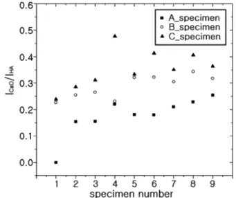
It showed that the longer spray distance, the more CaO created and the less crystallinity of HA coated film as shown in Fig. 3.
Particularly, A1 specimen (the shortest spray distance) showed almost zero CaO phase creation and the highest crystallinity. It can be explained by that as the longer spray distance, the longer HA powder will be exposed in a liquid phase, which will accelerate TCP (tricalcium phosphate) and TeCP (tetracalcium phosphate) phase formation which is not desirable.
Fig. 4 shows XRD spectra for “A” specimens which have the shortest spray distance with various combination
Fig. 1. SEM micrograph of the hydroxyapatite powder (AMDRY6021).
Fig. 2. (a) XRD patterns of hydroxyapatite after plasma spraying at incremental standoff distance and (b) XRD intensity of the principal HA peak.
Fig. 3. The ratio of ICaO and IHA.
Optimal Condition of Hydroxyapatite Powder Plasma Spray on Ti6Al4V Alloy for Implant Applications 213
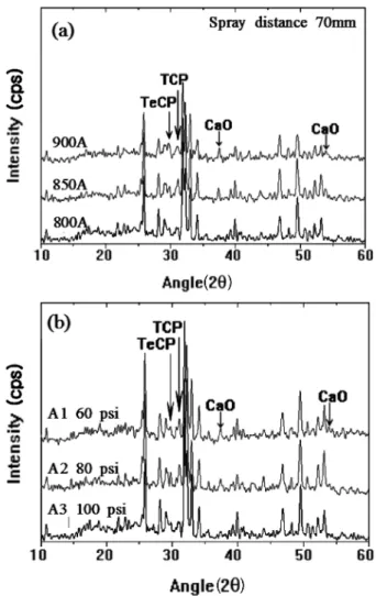
of current and auxiliary He gas pressure. As shown in Fig.
4 the higher spray current and auxiliary He gas pressure, the less crystallinity and non- desirable phase transition from HA phase occurred.
As auxiliary He gas pressure increases, HA powder spray speed increases accordingly. Thin lamellar structure was formed because the molten powder can spread more widely due to an increase of spray speed. Since thin coating layer have the higher cooling rate than a thicker one, OAP (oxyapatite) and amorphous phase
6)formation, which require the higher driving force than one for HA phase, can be accelerated. A1 showed the less amorphorization and the less HA decomposition than A3 or A7. As shown in Fig. 5, coating layers close to a substrate has the thinner lamellar structure than those close to the top surface.
Amorphorization occurs by the higher cooling rate due to quick absorption of the heat from HA powder to a substrate when molten powder strikes a substrate. HA re- crystallization and crystallization in coated films can be in- creased by lowering the cooling rate due to its low
temperature difference.
3.2 Adhesion strength of coated HA film
Fig. 6 shows the adhesion strength test results of that specimens.
The adhesion strength of the HA coated specimens was around 13~14 MPa except A3. From the result that A4, A5, A6 specimens have higher adhesion strengths than A1, A2, A3 specimens, it can be concluded that the higher spray power, the higher adhesion strength. The reason why
Fig. 5. Scanning electron microscope images of the cross-section;(a) A1, (b) A2, (c) A3, (d) A4, (e) A5 and (f) A6.
Fig. 4. (a) XRD pattern of hydroxyapatite after plasma spraying at different power and (b) XRD pattern of hydroxyapatite after plasma spraying at different aux gas.
Fig. 6. Adhesion strength of the hydroxyapatite coating specimens.
214 Hyo-Sok Ahn and Yong-Keun Lee
A3 specimen showed the lowest adhesion strength than the others can be explained by cracks (shown in Fig. 5) bet- ween the substrate and coating layers.
4. Conclusion
Most effective and influential condition on plasma spray coating was a plasma spray distance (“A” specimen) ob- served by XRD analysis. The optimal spray distance was 70 mm. It was observed that the higher a spray current and the higher an auxiliary He gas pressure, the less crystal- linity and the higher non- desirable phase transition from HA phase occurred. As for the adhesion strength, it was found that minimal spray power is enough to obtain good adhesion strength, even though the adhesion strength is increased with the spray power. Considering all the test results, the optimal plasma spray coated films were formed with spray distance of 70 mm, plasma current of 800 A, and auxiliary gas pressure of 60 psi.
Acknowledgement
This study was financially supported by Seoul National University of Science & Technology.
References
1. K. de Groot, J. Ceram. Soc. Jpn., 99, 943 (1991).
2. A. McNab, Aust. New Zeal. J. Ophthalmol., 23, 117 (1995).
3. H. Aoki, M. Akao, Y. Shin, Y. Tsuzi and T. Togawa, Medical Progress Through Technology, 12, 213 (1987).
4. R. J. Cronin, L. J. Oesterle and D. M. Ranly, Int. J. Oral Maxillofac. Implants, 9, 55 (1994).
5. O. R. Beirne, T. A. Curtis and J. S. Greenspan, J. Prosthet.
Dent., 55, 362 (1986).
6. K. A. Gross, C. C. Berndt and H. Herman, J. Biomed.
Mater. Res., 39, 407 (1998).