초음파센서기반 2휠구동로봇의 실시간 자율주행제어에 관한연구
A Study on Real-Time Autonomous Travelling Control of Two-wheel Driving Robot Based Ultrasonic Sensors
황원준1*, 박인만2, 강언욱2, 한성현3
Won-Jun hwang, In-Man Park, Un-Wook Kang, Sung-Hyun Han
<Abstract>
We propose a new technique for autonomous navigation and travelling of mobile robot based on ultrasonic sensors through the narrow labyrinth that leave only distance of a few centimeters on each side between the guides and the robot. In our current implementation the ultrasonic sensor system fires at a rate of 100 ms, that is, each of the 8 sensors fires once during each 100 ms interval. This is a very good firing rate, implemented here for optimal performance. This paper presents an extensively tested and verified solution to the problem of obstacle avoidance. Our solution is based on the optimal placement of ultrasonic sensors at strategic locations around the robot. Both the sensor location and the associated navigation algorithm are defined in such a way that only the accurate radial sonar data is used for accurate travelling.
Key Words : Ultrasonic sensors, Mobile robot, Obstacle avoidance, Autonomous Navigation and travelling
1*정회원, 교신저자, 경남대학교 첨단공학과, E-mail:[email protected]
2정회원, 경남대학교 첨단공학과
3정회원, 경남대학교 기계공학부 교수, 工博
1*Corresponding Author, Dept. of Advanced Engineering, Kyungnam University.
3Dept. of Advanced Engineering, Kyungnam University.
3Prof., School of Mechanical Engineering, Kyungnam University, Ph. D.
1. INTRODUCTION
This research about narrow-aisle navigation is based on ultrasonic sensors. A comprehensive discussion of the characteristics and limitations of these sensors can be found in the literature and is omitted here. This paper describes an experimental obstacle avoidance system for mobile robots traveling through the narrow aisles of a warehouse. [1, 3, 7, 9]
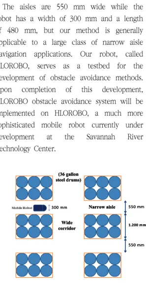
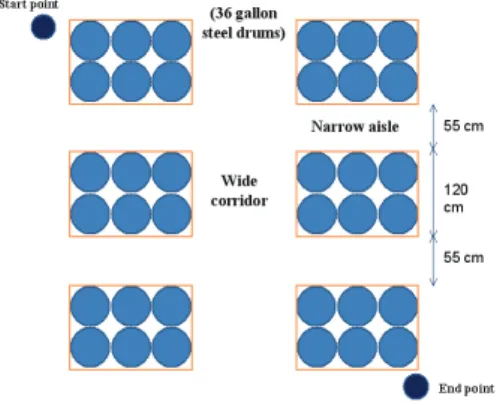
The aisles are 550 mm wide while the robot has a width of 300 mm and a length of 480 mm, but our method is generally applicable to a large class of narrow aisle navigation applications. Our robot, called HLOROBO, serves as a testbed for the development of obstacle avoidance methods.
Upon completion of this development, HLOROBO obstacle avoidance system will be implemented on HLOROBO, a much more sophisticated mobile robot currently under development at the Savannah River Technology Center.
550 mm
1.200 mm (36 gallon
steel drums)
Wide corridor
Narrow aisle
550 mm
300 mm 550 mm
1.200 mm (36 gallon
steel drums)
Wide corridor
Narrow aisle
550 mm
300 mm 550 mm
1.200 mm (36 gallon
steel drums)
Wide corridor
Narrow aisle
550 mm 300 mm
Fig. 1 The drums are stacked up on wooden forklift pallets
HLOROBO will be employed to traverse long aisles between stacks of 36-gallon steel drums, which are stored on forklift pallets as shown in Fig. 1
When travelling in narrow aisles that leave only a few centimeters on each side between the guides and the robot (about 120 mm in our application), a measuring accuracy on the order of 10-20 mm is necessary for smooth servoing along the center of the corridor.
The reasons are that the ultrasonic sensors are not suitable for narrow aisle navigation because of their poor angular accuracy.
For example, the widely used Polaroid ultrasonic sensors have a 15 radial accuracy of about 5 mm for short distances, but, with a 30 emission cone, the angular accuracy is extremely poor.
The purposed obstacle avoidance methods has been illustrated very useful for accurate travelling, because most systems are designed to respond to clusters of readings that indicate the existence of an object in a certain area of the world model. This is also evident in the great popularity of potential field-based obstacle avoidance systems.
Conventional "general- purpose" obstacle
avoidance systems usually surround the robot
with a ring of ultrasonic sensors installed at
15º intervals. For omni directional robots of
circular o shape, this design requires
360º/15º = 24 sensors mounted on a ring
around the robot. Similar designs using 24
sensors in 15º intervals are described in the
literature. [2, 4, 5, 6, 8, 10, 11]
This paper presents an extensively tested and verified solution to the problem. Our solution is based on the optimal placement of ultrasonic sensors at strategic locations around the robot. Both the sensor location and the associated navigation algorithm are defined in such a way that only the accurate radial sonar data are used for travelling.
2. HARDWARE, SENSORS SYSTEM AND CONTROLLER DESIGN
2.1 Hardware Design
The robot kit includes the control software, out-case covers, aluminum beams and plastic connectors to build a chassis, two assembled nonholonomic scooter wheels powered by two stepper motors, one 360 degree rotating caster wheel, a power module, a battery (12V 7A), and a web-camera. The experimental robot also carries additional accessories, eight infrared sensors and extra beams and connectors for reinforcement. A computer Intel (R) Core(TM) 2 CPU 6400 @ 2.13 GHz & 2.00 GB of RAM is used as a controller device, and Windows XP Professional is loaded as the operating system. The extensions (extra cameras, sensors and grippers) can be easily added to the system if necessary.
The intelligent mobile robot (HLOROBO) with nonlinear dynamics is approximated by a fuzzy control model. The control algorithm
should have the ability to recognize and adapt itself to the surrounding environment with obstacles. Since a PID controller has only one linear control rule, design for adaptive control is difficult when an exact model cannot be obtained. Since a fuzzy logic controller is constructed from linguistically expressed rules, it is easy to derive control rules from human experiential knowledge, to understand them, and to improve them in detail. For these reasons, the control performance obtained by fuzzy control is much better than that of a PID.
Steering and speed control of an intelligent mobile robot cell can be performed by fuzzy control techniques. This control procedure needs to recognize the environment around the mobile robot cell and make suitable decisions in order to drive with stable motion. The recognition can be achieved using various sensors and technique such as ultrasonic sensors and voice recognition technique. The performance of the control system depends on the fuzzy rule sets evaluating the parameters obtained from the reflections.
2.2 Sensors System
The sensors (MA40B8R) are located on HLOROBO as shown in Fig. 2.
The purpose of sensors S1 and S6 is to
show if there is an aisle or corridor opening
at either side of the robot. Sensors S3 and
S4 are used for simple
However, the most important sensors in this robot are the sensors S2 and S5, because they offer several important benefits, especially for the purpose of servoing along the center line of the narrow aisles, it is of great benefit to be able to measure (and therefore know) the locus of the aisle's center line before the HLOROBO’s body gets there.
The ultrasonic sensors system fires at a rate of 100 ms, that is, each of the 6 sensors fires once during each 100 ms interval. This is a very fast firing rate, implemented here for optimal performance. We believe that slower firing rates would also work, because all sensor-triggered critical decisions are made after the vehicle slowed down in anticipation of a critical decision.
Our ultrasonic sensor system is based on the widely used ultrasonic transducers from Polaroid, together with the standard Polaroid circuit boards. Since the minimum range of these sensors (200 mm) is not suitable for our application, we have added to each board a custom circuit that allows a minimum range of 80-100mm (the exact range varies as a function of temperature and other external factors).
All sensors are mounted at a height h = 100 mm, which assures that their center, is at the same height as the upper horizontal edge of the forklift pallets (see Fig. 2(b)).
Since the sensors measure the distance to the closest object, they will "see" the pallet most of the time. However, if a drum
C as tor wheel
D rive Wheels
300 mm S1
S2
S3 S4
S8 H ead
left s ens or
H ead rig ht s ens or
B ody right s ens or B ody
left s ens or
S5
S6
S7 C ommon obs tacle avoidance s ens ors
C as tor wheel
D rive Wheels
300 mm S1
S2
S3 S4
S8 H ead
left s ens or
H ead rig ht s ens or
B ody right s ens or B ody
left s ens or
S5
S6
S7 C ommon obs tacle avoidance s ens ors
(a) Location of the ultrasonic sensors
Floor h = 100 mm D rums
R obot S onar
Wooden forklift pallet Floor h = 100 mm
D rums
R obot S onar
Wooden forklift pallet (b) sensors is mounted at the same height as the
upper horizontal edge of the pallets Fig. 2 The position of ultrasonic sensors
protrudes by a few inches (as is expected in our application), then the sonars will "see"
the protruding part of the drum.
2.3 Controller Design
The characteristic needed for all autonomous mobile robots is obstacle avoidance ability that helps mobile robots move without collision in unmodified environ- ments. Ultrasonic range finders can be used to avoid collision with unexpected obstacles.
The data from ultrasonic sensors is the
distance between the ultrasonic sensor and object, which is adjusted and given directly to the fuzzy input. Therefore, the ultrasonic sensor locations are very important.
The fuzzy controller is based on the knowledge and experience of human operators, known as intelligent control. Each fuzzy controller for HLOROBO has eight inputs and two outputs. Both inputs and outputs have three membership functions.
Each membership function is considered as a Gaussian function. The construct of these membership functions can be applied to neural-fuzzy control.
Behavior-based approaches [8] have been established as a main alternative to conventional robot control in recent years.
The architecture of these approaches provides high capability, while limiting the complexity of the individual modules. These approaches can be implemented and tested independently.
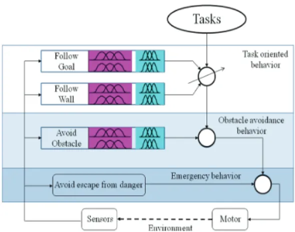
The system architecture in this application is based on behavior-based approaches which has three levels. The highest level behavior is called task-oriented behavior which consists of two subtasks, wall following and goal following. The lower level behavior is an obstacle-avoiding behavior and the lowest is an emergency behavior.
A control system based on the traditional Proportional, Integral, and Derivative technique may implement low-level behaviors.
A high-level behavior may require intelligent control techniques such as fuzzy control.
Fuzzy control can be applied for autonomous
mobile robots which have complex control architectures. The application of the robotic reactive control approaches, particularly in the layered control system, are presented by Safotti, et al. [9]. Yen and Pluger developed and tested a new defuzzification technique for alleviating difficulties in applying existing defuzzification methods for mobile robot navigation control.
There are three steps for designing a fuzzy controller: fuzzification, inference engine, and defuzzification.
Fuzzification is defined as the mapping from a real-valued point to a fuzzy set. In most fuzzy decision systems, non-fuzzy input data is mapped to fuzzy sets by treating them as singleton membership functions, Gaussian membership functions, triangular membership functions, etc. The Gaussian fuzzification maps
∈into fuzzy set A’ in U has the following Gaussian membership function:
′ exp
exp
(1)
Where
are positive parameters and the t-norm * is usually chosen as algebraic product or min.
a) Read Ultrasonic data and construct
three membership functions for
input:
Fig. 3 Membership functions for avoiding obstacles
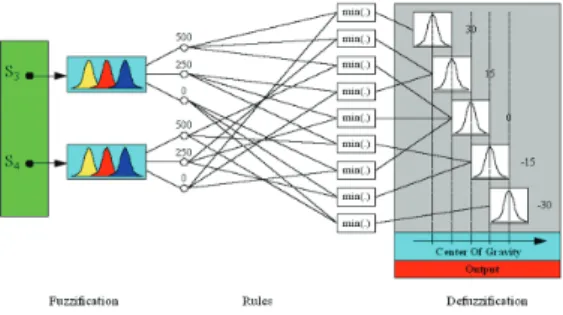
All data from Ultrasonic sensors are received and displayed. In this case, we want to construct three membership functions for each input on its universe, that is, zero distance (0 mm), middle distance (250 mm), and long distance (500 mm) as shown in Fig. 3. Each membership function is considered as a Gaussian curve membership function. The Gaussian curve depends on two parameters
and
as given by
exp
(2)
b) Construct five membership functions for output:
From our experiments, we construct five membership functions for angular velocity:
Positive (30), small-positive (15), zero (0), small-negative (-15), and negative (-30) as given in Fig. 3
Fuzzy Inference Engine is used to combine the fuzzy IF-THEN in the fuzzy rule-base, and to convert input information into output membership functions. An inference mechanism emulates the expert's decision-making in interpreting and applying knowledge about how to perform good control.
This can be implemented as a fuzzy rule-base. The rules may use the experts experience and control engineering knowledge. Fuzzy rule base consists of a collection of fuzzy IF-THEN rules, which can be shown as the following forms:
∩∩
(3)
There are three types of fuzzy rule-based models for function approximation: Mamdani model, Takagi-Sugeno-Kang model, and Kosko's additive model.
The following interpretations are used for the fuzzy IF-THEN rule.
Min-operation rule of fuzzy implication:
→ min
(4)
Product-operation rule of fuzzy implication:
→
(5)
The rules for avoiding frontal obstacles and the rules for the following behavior (eg.
Left side) are shown in Table 1and 2. The Ultrasonic sensors notations are the same as shown in Fig. 2 for convenience. The rule base of each table depends on the sensor arrangement.
ω S4
S3 0 250 500
0 0 -15 -30
250 15 0 -15
T
able 1 Rules for avoiding frontal
obstacles
The results from Table 1and 2 are obtained by the following nine rules:
If S
3=0 and S
4=0 Then ω = 0
(6) If S
3=0 and S
4=250 Then ω = -15 If S
3=0 and S
4=500 Then ω = -30 If S
3=250 and S
4=0 Then ω = 15 If S
3=250 and S
4=250 Then ω = 0 If S
3=250 and S
4=500 Then ω = -15 If S
3=500 and S
4=0 Then ω = 30 If S
3=500 and S
4=250 Then ω = 15 If S
3=500 and S
4=500 Then ω = 0
ω/v S
2S
1-250 0 250
-250 -15/1 15/1 30/1
0 -15/1 0/2 15/1
250 -30/1 -15/1 15/1
Table 2 Rules for the wall following behavior (e. g left side)
There are many methods which can be used for converting the conclusions of the inference mechanism into the actual input for the process or for the plant. Center of Gravity (COG) defuzzification method is defined as equation (7). This procedure, also called Centroid method or Center of Area, is the most prevalent and physically appealing of all the defuzzification methods.
(7)
The combination result of the fuzzy logic systems with centroid defuzzification (7), product-inference rule, singleton fuzzifier, and Gaussian membership function (1) can be obtained as equation (8).
exp
exp
(8)
In this step, we will defuzzify the
membership function for the control action
of angular velocity using the centroid
method. Using min-operation rule of fuzzy
implication, we obtain two outputs as
equation (9), (10).
min ×
min ×
(10) …
min × (a) The process of fuzzy inference system for
obstacle avoidance
(b) The three steps for designing of fuzzy controller
Fig. 4 Fuzzy inference system and three steps for designing a fuzzy controller
min ×
(9)
min ×
min ×
min ×
min ×
min ×
min ×
min ×
min ×
From Table 2, we obtain:
Finally, the output for angular velocity is given by
(11)
Fig. 4 shows an example of a fuzzy inference system for obstacle avoidance using ultrasonic sensor S3 and S4, and shows the 3 steps for fuzzy controller.
2.4 Behavior-Based Design
There are many applications of behavior- based approaches that have been presented during the last few years. Intelligent mobile robot control can use multiple behaviors to generate several controls in the systems. The results showed that mobile robots can learn from demonstration. The research behavior- based topics for mobile robots are still being developed by many researchers.
The behavioral architecture in this paper is
based on fuzzy control. The behavior-based
fuzzy control of HLOROBO consists of several
behaviors. Each behavior represents a concern
in mobile robot control and relates Ultrasonic
Fig. 5 Behavior-based fuzzy control architecture for obstacle avoidance
sensor data, robot status data and goal information to control robot. A simple architecture is shown in Fig. 5.
2.4.1 Obstacle Avoidance Behavior If the obstacles are located closer than the emergency distance, the robot will be stopped from moving, known as emergency behavior. During this behavior, the robot will sound an alarm and states the obstacles location. The robot will check the obstacles from left to right. The emergency behavior has a higher priority than other behaviors.
The first behavior of HLOROBO is an emergency behavior, which has a higher priority than other behaviors. Since this behavior depends on the safety distance, the ultrasonic sensor data is used directly.
All data from ultrasonic sensors are used in this step. An emergency distance needs to be defined for Emergency Behavior. Ultrasonic sensors from the head-left, head-right, left
and right have different emergency distances.
All sensors in front must add 80-100 mm for offset distance, the exactly distance depends on the environmental, e.g. temperature. From our experiments, it was shown that the closest obstacle should be greater than 90 mm after offset.
Ultrasonic sensors on the left, check objects on the left. If the objects are presented, the robot will stop moving.
Ultrasonic sensors on the front (head sensors) and right perform in the same manners.
Therefore, the results of emergency behavior are shown as follows:
Check the object from the head-left, head-right, left, and right side respectively.
Stop moving and alarm if the objects are closer than the safety distance (90 mm).
Tell the objects location.
The behavior will follow this process until all ultrasonic data show the distance is greater than 90 mm. However, an emergency distance can be given by the user.
If the obstacles are detected in the front right of the robot, the obstacle avoidance behavior will be working. If the robot has no tasks, the robot is in wandering situation.
The robot turns left until the angular velocity is close to zero (fuzzy output equals to zero).
The obstacle avoidance behavior uses
Ultrasonic data to generate a fuzzy set that
represents the distance relating to
HLOROBO’s location. The behavior is
operated by using the fuzzy controller. The fuzzy inputs are the fuzzy sets from sensors mounted on the HLOROBO, the output is the avoiding rotation.
Eight ultrasonic sensors mount on the robot are used as the fuzzy inputs. The rule bases are constructed the same as Table 1.
The fuzzy output is the summation of each output from each controller. Therefore, the output value depends on the data from ultrasonic sensors which are presented as the fuzzy inputs. There are three membership functions for each input. The output is the avoiding rotation. The results of obstacle avoidance behavior are shown as follows:
Turn Right: If the obstacle is located on the Head-left side. Then HLOROBO will turn right.
Turn Left: If the obstacle is located on the Head-right side, then HLOROBO will turn left.
However, if there are obstacles located closer than an emergency distance, this behavior will be ignored.
2.4.2 Task Behaviors
Goal following and wall following behaviors are the task oriented behaviors.
Goal following behavior is the desired task which will be assigned as the user provides.
This is a simple behavior that commands HLOROBO to move. If there is no obstacle between HLOROBO and the goal, the goal following behavior is activated. With respect
to HLOROBO’s position and orientation, HLOROBO turns and goes straight to the goal.
Theuser needs to provide the velocity for the goal following behavior. If an emergency behavior and an obstacle behavior do nothing, then HLOROBO will move ahead as the user assigns. However, this is neither a goal point nor the target. More sensors such as gyro, compass, and other navigation systems may need to be used. Therefore, this behavior is simply the command that tells the robot to move forward.
Ultrasonic data, target position, and HLOROBO’s location are given directly to the goal following behavior. To make HLOROBO move to the target, an attractive force is exerted to the target position that will try to pull HLOROBO toward the goal. A constant-magnitude attracting force, Fct pulls the robot toward the target point, whose coordinates known to the robot. The attracting force Ft is given by equation as follows.
(12)
where: Fct is the force constant (attraction to the target), dt is the distance between the target and the robot,
xt,
ytare the target coordinates.
HLOROBO will stop moving, and turn itself
to a desired heading. If a new target is
commanded from this point, HLOROBO will
active the goal following behavior to go to
the new position.
Two ultrasonic sensors mounted on the left side and two ultrasonic sensors mounted on the right side are used for the wall following.
The HLOROBO can follow the wall on the left side or the right side as the wall following is assigned. The user gives the distance between the robot and wall which is controlled by a fuzzy controller. HLOROBO was implemented in the real situation. When the distance between the robot and wall, is controlled by the fuzzy controller, the robot will be tracking the wall distance.
This behavior determines the desired turning and moving direction in four steps based on HLOROBO’s current location. First, HLOROBO locates the closest wall between the left side and right side. Second, the behavior computes the wall distance, for example, the distance between the current position of HLOROBO and the wall. Third, the fuzzy controller is used to control the wall distance. Finally, HLOROBO moves ahead if the error from the third step is zero.
The design of wall following behavior is quite simple if it makes use of a single sensor, which gives the distance to the wall.
However, by using more sensors, the behavior becomes more reliable.
HLOROBOfinds the closet wall. If the wall on the left side is closer than the right side, HLOROBO will track the wall on the left side. If the distance between the robot and wall is about tracking, the robot will move forward as the velocity value is assigned. A
E mergency?
O bs tacle?
T as k?
S top?
G et date from Ultras onic s ens ors
Avoidance B ehavior
S top S tart
S top
G oal s eeking Wall following
E mergency?
O bs tacle?
T as k?
S top?
G et date from Ultras onic s ens ors
Avoidance B ehavior
S top S tart
S top
G oal s eeking Wall following
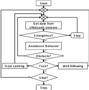
Fig. 6 Flow chart for behavior-based system
simple flow chart of behavior-based design is given in Fig. 6.
3. IMPLEMENTATION
The behavior-based fuzzy control for HLOROBO was tested follows Emergency behavior, Obstacle Avoidance Behavior and Task Oriented behavior, separately. The results show that this complicated system can be solved. Each behavior works correctly. In order to design the mobile robot for unmanned FA, this paper describes an experimental obstacle avoidance system for mobile robot traveling through the narrow aisles of a warehouse.
In this paper, we discuss four basic motion
components which were the focus of our
research work, because these components
needed to be automated in our application.
These basic components allow the robot to travel continuously and perform routine inspections. The other remaining components represent transient conditions that are out of this research and may be needed only rarely.
These characteristics are summarized as following :
Firstly, Travel along the center line of a narrow aisle. Secondly, Turn out of an aisle and into a corridor (90°). Thirdly, Driving in a main corridor, looking for the next aisle.
Fourthly, Turn into an aisle after travelling in a main corridor.
Before discussing in detail, some frequently used terms should be defined:
In this paper, "Guide" means Any physical obstruction alongside the desired direction of travel. In the HLOROBO application, Guides usually consist of 36 gallon drums standing on wood pallets. The drums are expected to be flush with the horizontal edge of the pallet, or they may protrude or be recessed by up to 10 cm. Since the snares are mounted at the same height as the horizontal edge of the pallets, they will "see" the horizontal edge of the pallet in-between drums, if a drum is missing (but the pallet is there), or if a drum is recessed. Alternatively, if as drum protrudes beyond the horizontal edge of the pallet, the sonars will "see" the protruding part of the drum (subject to limitations of specula reflections).
And "No-Guide" means a name for
ultrasonic range readings that are larger than a certain threshold. Readings larger than this threshold are interpreted as "there is no guide;" readings smaller than (or equal to) this threshold are interpreted as "there is a guide." The no-guide (NG) value is computed such that they represent the largest range possible within the aisle. For the body sensors:
max
For the head sensors:
max
where :
maxis maximal aisle width,
is width of HLOROBO base,
is Distance between Body sonar and longitudinal center of HLOROBO base,
is Distance between Head sonar and longitudinal center of HLOROBO base.
3.1 Travel along the center line of a narrow aisle.
The velocity variation:
a) Acceleration for L0 = 240 mm (i.e., the first 240 mm in the beginning of motion) b) The end of strategy is verified by three
consecutive readings of both the head and the body sonars. All six readings must exceed the no-guide threshold before the robot begins the "Turn out of an aisle and into a corridor (90°)"
motion component. This prudent strategy
is feasible because of the deceleration
phase described in (c) as follows.
Fig. 7 The robot measures the width of the aisle every one centimeter and computes the locus of the center point Ni. Ni is
temporarily stored and, 10 intervals (= 100 mm) later, used as the momentary target point for steering
c) Deceleration is invoked when the head sonar (of the side around which the next rotation is pending) "sees" no-guide as shown in Fig. 7 Deceleration for the longitrudinal distance between the head and body sonars: LFC = 240 mm. The main benefit of this deceleration phase (other than smooth motion) is that the robot speed is very low when the body sonar reaches the edge of the aisle.
Therefore, the body sonar's reading that is tested for the exit condition can be verified by taking multiple readings.
Taking multiple readings at the vehicle's normal operating speed might take relatively long and allow the robot to exit too far out of the aisle before the exit condition is confirmed.
Control Methods:
Range measurements from the head sensors are used to determine the absolute coordinates of the center of the aisle N. At a
speed of 100 mm/sec and a firing rate of 100ms, a new center point Ni can be computed at intervals of 100 msec × 100 mm/sec = 10 mm of travel. Ni is then stored in a ring buffer that holds 10 elements. This way, the newest element in the buffer is the present Ni=1 and the oldest element is Ni-10 (i.e., 10×1 0 mm = 100 mm behind Ni). The control algorithm distinguishes among different states:
a) During steady-state, the motor controller controls the speed of the motors such that HLOROBO's center point G aims at Ni-10 (i.e., at a point that is 10 cm behind Ni).
b) During the first 100 mm of travel, Ni-10 has not been computed yet. During this transient distance the speed of the motors is controlled such that HLOROBO's center point G aims at the oldest existing N (i.e., N1). Steady-state is reached when i
> 11, and Control Methods (a) goes into effect.
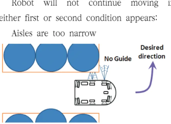
Robot will not continue moving if either first or second condition appears:
Aisles are too narrow
(a) HLOROBO begins to decelerate when the head side sensor "sees" no-guide
(b) HLOROBO begins to turn when both of the head &
body sensors "see" no-guide
Fig. 8 Control methods of HLOROBO
If an object is close to a side of the aisle but small enough to allow passage, then either it will be detected by sensors S3 and S4 as an obstacle, or it will be treated as a legitimate protrusion of the guide. In the latter case, HLOROBO measures and computes the exact width of the remaining opening and compares it with a threshold for the minimum allowable aisle width, which is 45cm in our application. If the measured width is above the threshold, HLOROBO will continue and plot its path along the center between the protrusion and the other guide.
If the measured width is below the threshold, HLOROBO stops and notifies the operator.
An obstacle is detected in the robot's path If either of the two obstacle detection sensors (S3 and S4 in Fig. 2) detects an obstacle ahead of the robot, HLOROBO stops.
Unlike in most common obstacle avoidance systems, in our application there is no point in trying to circumnavigate an obstacle: if an obstacle is present in a narrow aisle, then the aisle blocked. At this time the system may alert the operator or maneuver backward out of the aisle, depending on the application.
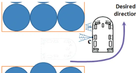
3.2 Turn out of an aisle and into a corridor .
Control Methods:
The controller computes and maintains motor velocities so that the robot turns around a center of rotation ‘C’ about 90°
(see Fig. 9). In our application ‘C’ is located on the outer perimeter of the robot. Rotation about ‘C’ guarantees that HLOROBO will not collide with either one of the guides of the aisle out of which the robot is exiting.
Robot stops if an obstacle in the robot's path is detected.
Fig. 9 HLOROBO rotates around point C until the end of strategy is met
This strategy will complete if:
a) According to direction of rotation, either head right sensor or head left sensor measure a range of
≤
where: CW: Arbitrarily chosen reference steady-state distance between the HLOROBO side and the corridor side of the guide.
b) The rotation of 900 is completed. This
exit condition is to serve as a safeguard
if the primary exit condition (above) fails.
3.3 Driving in the main corridor, looking for the next aisle
The velocity variation
This motion component comprises of driving through a short distance of roughly straight-line motion along the short side of a rectangular pallet/drum guide, until the next aisle is encountered.
Control Methods:
This motion component has two distinct control strategies. Strategy (a) governs the motion while the body sonar of the robot that is facing the guide "sees" the guide. This condition is shown in Fig. 10(a) Strategy (b) governs the motion while the head sensor
"sees" no-guide, as shown in Fig. 10b. Both strategies are described in more detail below.
a) The short side of the rectangular pallet/drum guide has the width of two rows of drums that is 2 × 600 mm = 1200 mm.
b) When both the head and body sonar’s reaches beyond the edge of the next aisle, the robot stops and prepares to turn in an aisle.
Robot will stop if an obstacle in the robot's path is detected. If both of head sonar and body sonar sees no-guide, that’s reason for the end of strategy.
(a)
(b)
(c)Fig. 10 HLOROBO travelling along the short side of a drum/pallet guide: When body sensor "sees" no-guide the robot is stop
and then turn into the next aisle
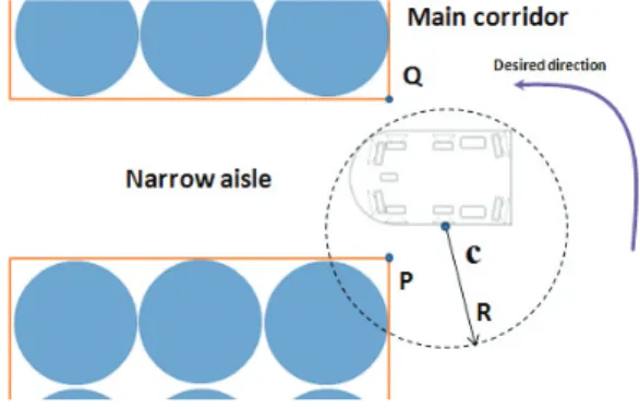
3.4 Turn into an aisle after travelling in a main corridor.
Control Methods
"Turn into an aisle after travelling in a
main corridor" is the most critical motion
component, because it is the motion during
which a collision is most likely. Conventional
solutions aim at measuring the location of
corner points A and Q and computing a path
between these two points. The technical difficulty with such an approach lies in the difficulty of locating point Q precisely, especially when the robot approaches from the direction shown in Fig. 10 Our method differs from conventional ones in that it does not require any sensor-derived measurements of point Q and it requires only vague measurements of point P. To understand how our method works we have to recall some characteristics of the previous motion component are as follows.
Fig. 11 The geometry progressive just prior to turn into an aisle after travelling in a main corridor
During the "travel in a corridor looking for a new aisle" motion the robot tried to maintain a certain distance Cw = 100 mm from the narrow side of the guide, the robot is aligned in parallel with the narrow side of the guide when exiting that motion. Upon exiting, the robot's drive axis must necessarily be beyond P, because the body sensor, located exactly along the drive axis, is already "looking" into the aisle. Therefore, a 90º rotation around point ‘C’ is
guaranteed not to collide with corner P. This approach does not consider point Q at all, but it will work as long as the narrow aisle is "sufficiently" wide. Just how much is
"sufficient" depends on the geometry and dynamics of the robot, as well as on the ultrasonic properties of the sensors and the environment.
Fig. 12 HLOROBO is turning into a narrow aisle
Let us assume the ideal condition, in which the robot is aligned in parallel to the short side of the guide and travels at the desired distance Cw = 120 mm from the guide. Let us further assume that there are no delays in the sonar measurements and that the sonar emission cone is exactly
=30 wide, as shown in Fig. 11 under these ideal conditions the body sensor located at point ‘C’ in Fig. 11 will see no-guide at the moment when the axis of the robot has advanced a distance x beyond the corner of the guide P. In the subsequent rotation around ‘C’ no part of the robot will protrude outside a circle of radius R, as shown in Fig.
11 Note that R is only a function of the
geometric properties of the robot; for HLOROBO we measured R = 460 mm. From the geometry of Fig. 11 we can now derive that the condition W > x + y will guarantee collision-free turning into the aisle. It is easy to see from Fig. 11 that
tan
and that
so that the condition for collision free turning becomes
tan
Substituting the numeric values of our application into the above equation, we assume:
tan
The result of above Equation shows that theoretically the robot could safely enter any aisle of width W > 480 mm. In practice, of course, there are significant delays to consider. For example, it is not guaranteed that the body sensor is sampled at exactly the position shown in Fig. 11. Furthermore, for reliable operation it is necessary not to act immediately on the first no-guide reading from the body sensor, but rather to take multiple readings (three, in our application) for verification. Multiple readings, of course, introduce further delays. On the other hand, we recall the robot decelerates as soon as the head sensor sees no-guide, and that therefore the robots speed is very slow when these delays are incurred. In our experiments we found that the delays (caused by the three readings taken for verification of the end of strategy) equate to only 1-2
centimeters travel. At a slower firing rate, for example at 200 ms, proportionally longer delays can be expected.
4. EXPERIMENT AND RESULTS
Our experimental vehicle-HLOROBO, shows in Fig. 13 is equipped with 8 Polaroid ultrasonic sensors, which we customized for short range measurements (80-100 mm). This approach emphasizes the importance of the optimal location of the sonar to achieve extremely reliable and robust performance.
Most successfully implemented conventional general purpose obstacle avoidance algorithms rely on a statistical interpretation of the often inaccurate sonar range data. Because of the statistical uncertainty inherent in these systems they cannot avoid occasional collisions, especially when navigating in narrow aisles or doorways. By contrast, the algorithm presented in this paper has been shown to cope reliably and repeatable with narrow aisles and narrow-aisle entry, even under changing conditions.
Fig. 13 The picture of the HLOROBO Robot
The experimental number
The successful number
1 ○
2 ○
3 ○
4 ○
5 ○
6 ○
⋮ ⋮
500 494(about 99%) Table 3 The experimental number and success
rate
Our experiment was done about 500 times to approve our research contents in laboratory environment as shown in Fig.14 (start point→end point) experimental result was listed and analysed as table 3
Fig. 14 Layout of experiment
5. CONCLUSION
In this paper, we have proposed a new technique for autonomous navigation and travelling based on ultrasonic sensors of
mobile robot. Also, this paper has presented
an extensively tested and verified solution to
the problem of obstacle avoidance. This
solution is based on the optimal placement
of ultrasonic sensors at strategic locations
around the robot. Both the sensor location
and the associated navigation algorithm are
defined in such a way that only the accurate
radial sonar data are used for travelling. The
purposed technique of obstacle avoidance
has been illustrated very useful for accurate
autonomous travelling. This is also evident in
the great popularity of potential field-based
obstacle avoidance systems. In future, we are
going to adapt this technique for the real
line process of FA.
REFERENCES
1) Borenstein, J. and Koren, Y., 1988,
"Obstacle Avoidance With Ultrasonic Sensors." IEEE Journal of Robotics and Automation, Vol. RA-4, No. 2, pp.
213-218.
2) Borenstein, J. and Koren, Y., 1989,
"Real-time Obstacle Avoidance for Fast Mobile Robots." IEEE Transactions on Systems, Man, and Cybernetics, Vol. 19, No. 5, Sept/Oct, pp. 1179-1187.
3) Bozma, Ö. and Kuc, R., 1991,
"Characterizing Pulses Reflected From Rough Surfaces Using Ultrasound." Journal of the Acoustical Society of America, Vol.
89, No. 6, pp. 2519 -2531.
4) Buchenberger, M., Jörg, W., and Von Puttkamer, E., 1993, "Laserradar and Sonar-based World Modelling ," IEEE Conference on Robotics and Automation, Atlanta Georgia, May 10-15, pp. 534-541.
5) Crowley, J. L., 1989, "World Modeling and Position Estimation for a Mobile Robot Using Ultrasonic Ranging,"
Proceedings of the 1989 IEEE International Conference on Robotics and Automation, Scottsdale, Arizona, May 14-19, pp. 674-680.
6) Everett, H. R., Gilbreath, G. A., Tran, T.
and Nieusma, J. M., 1990, "Modeling the Environment of a Mobile Security Robot,"
Technical Document 1835, Advanced Systems Division, Naval Ocean Systems Center, San Diego, California 92152-5000, June.
7) Flynn, A. M., 1988, "Combining Sonar and Infrared Sensors for Mobile Robot
Navigation," The International Journal of Robotics Research, Vol. 7, No. 6, December, pp. 5-14.
8) Holenstein, A. A. and Badreddin, E., 1991,
"Collision Avoidance in a Behavior-based Mobile Robot Design," Proceedings of the 1991 IEEE International Conference on Robotics and Automation, Sacramento, California, April, pp. 898-903.
9) Kuc, R. and Barshan, B., 1989,
"Navigating Vehicles Through an Unstructured Environment With Sonar,"
Proceedings of the IEEE International Conference on Robotics and Automation, Scottsdale, Arizona, May 14-19, pp. 1422-1426.
10) Moravec, H. P., 1988, "Sensor Fusion in Certainty Grids for Mobile Robots," AI Magazine, Summer, pp. 61-74.
11) Pin, F. G. et. al., 1989, "Autonomous Mobile Robot Research Using the Hermies-III Robot," IROS International Conference on Intelligent Robot and Systems, Tsukuba, Japan, Sept.
(접수:2014.07.04. 수정:2014.07.15. 개제확정:2014.07.18.)