한국정보통신학회논문지 Vol. 23, No. 10: 1269~1274, Oct. 2019
5G 응용을 위한 반원형 구조를 가진 사각형 마이크로스트립 패치 안테나
김영진1·자남 마하르잔2·최동유3*
Rectangular Microstrip Patch Antenna with Semicircular Structure for 5G Applications
Yeong-Jin Kim
1· Janam Maharjan
2· Dong-You Choi
3*1
Professor, Department of Automatic System, Chosun College of Science & Technology, Gwangju, 61453, Korea
2
Graduate student, Department of Information and Communication Engineering, Chosun University, Gwangju, 61452, Korea
3*
Professor, Department of Information and Communication Engineering, Chosun University, Gwangju, 61452, Korea
요 약
본 논문에서는 5G 어플리케이션을 위한 네 개의 마이크로스트립 패치 배열 안테나를 설계 및 분석하였다. 제안한 배열 안테나는 네 개의 사각형 마이크로스트립 패치 안테나로 구성되며, 배열 안테나의 양쪽 측면에 반원형 에칭구 조가 포함된다. 안테나는 시리즈 및 동일 급전 네트워크를 사용하여 공급되며, 하단의 접지면은 안테나의 주파수 특 성을 개선하기 위해 변경된다. 마지막으로 안테나의 지향성 특성을 향상시키기 위해 야기-형 구조가 추가된다. 제안
한 마이크로스트립 패치 배열 안테나는 21.95 ∼ 31.86 ㎓의 넓은 주파수 대역폭을 확보하였다. 안테나의 이득은 28
㎓ 대역에서 9.7 ㏈i의 이득을 보였으며, 제안한 주파수 대역 전반에 걸쳐 높은 이득과 높은 지향성을 유지하였다. 제 안한 안테나는 낮은 프로파일과 간단한 구조로 인해 5G 어플리케이션을 위한 좋은 대안될 수 있을 것이다.
ABSTRACT
The paper presents a design of simple four-element microstrip-patch array antenna that is suitable for 5G applications.
The proposed array consists of four rectangular microstrip patch elements with semicircular etches made on both sides of each elements. The antenna is fed using the combination of series and corporate feeding networks. The size of the ground is also changed to improve the antenna frequency. Finally, yagi elements are also added to improve the directive gain of the antenna. The presented microstrip patch array is able to achieve wide frequency bandwidth of 21.95-31.86 GHz. The antenna has also attained gain of 9.7 dB at 28 GHz and has maintained high gain and high directivity throughout the frequency band. The proposed array antenna fed by series-corporate feeding network, with low profile and simple structure is a good candidate for 5G applications.
키워드
: 마이크로스트립 패치 안테나, 패치 배열 안테나, 5G 어플리케이션, 야기 구조
Keywords
: Microstrip patch antenna, Patch array antenna, 5G application, Yagi structure
Received 12 June 2019, Revised 3 July 2019, Accepted 6 September 2019
* Corresponding Author Dong-You Choi(E-mail:[email protected], Tel:+82-62-230-7060)
Professor, Department of Information and Communication Engineering Chosun University, Gwangju, 61452 Korea
Open Access
http://doi.org/10.6109/jkiice.2019.23.10.1269
print ISSN: 2234-4772 online ISSN: 2288-4165Ⅰ. Introduction
Evolution is inevitable in field of technology, and with the recent implementation of 4th generation of mobile communication (4G) in many countries, the world now looks on to 5th generation (5G) for the future.
The current global demand for wireless devices is very high. Especially, with rapid growth in the field of IoTs (Inter of Things), the demand for bandwidth has increased. This has eventually created global bandwidth shortage in today's wireless cellular networks. The fifth-generation (5G) communication system is the answer to the new demands as the technology has large amount of available spectrum, can achieve high data rate (10-50 Gbps) and very high device density. 5G will exploit millimeter-wave bands [1] and further improve the communication experience.
Microstrip patch antennas have been preferred for various commercial wireless applications due to its conformability, smaller size, easier fabrication, lower cost, lighter weight and high-density packaging. It supports various feeding techniques and further, to improve the gain and achieve the desired pattern requirements, microstrip can be developed into arrays as well. Many 5G antennas have been developed using microstrip patch technology. For better results, microstrip antenna arrays have also been employed and researched for 5G applications [2] –[6].
One of the advantages of microstrip patch antennas is the easy techniques of feeding the system. In the array of microstrip patches, elements can be fed using single line or multiple lines. There are various feeding methods:
series feed network, corporate feed network and corporate- series feed network [7].
Millimeter waves are susceptible to high propagation loss because of atmospheric absorption. Thus, while designing a system for 5G, the loss factor, which reduces gain performance of antenna, must be considered [8]. In addition, problems relating to link stability and high transmission loss could be faced for mm-wave applications.
performance of the antenna.
Numerous mm-wave antennas with good gain have been researched for 5G applications. A tilted antenna is proposed in [9], which is designed by combining a patch and waveguide aperture. However, the design in not suitable for integration. A stacked patch broadband antenna operating at 28 GHz is presented in [10] suitable for 5G communication. However, the antenna is affected by poor radiation. Dual band (28/38 GHz) antenna element with circular polarization was reported in [11].
However, the bandwidths are considerably narrow (less than 3%). The bandwidth and the gain of antenna can be improved by applying various techniques. One of those techniques is to add parasitic patches. However, this technique leads to high profile and cost [12].
Defected ground structures (DGS) is another way of improving gain and bandwidth by deliberately constructing a defect in the planar geometry of the ground [13]. In this paper, a simple 4-element microstrip patch array antenna with series-corporate feed system is presented for 5G applications. The use of series- corporate feed, along with Yagi elements, and employment of DGS have improved the gain and directivity of the antenna. In addition, the improvement in directivity along the frequency bandwidth reduces the propagation loss faced by the millimeter waves. The detailed antenna array design will be discussed in the paper.
Ⅱ. SINGLE ELEMENT
2.1. Single Element Antenna Design
At first, using rectangular patch design equation [14],
tentative length and width of patch was calculated as 1.7
mm and 3.26 mm respectively for 28GHz operating
frequency. However, to increase the bandwidth, the
parameters for single element patch was drastically
optimized to 2.75mm × 12mm (L × W) respectively. The
proposed single element antenna of size 10 ×12 ×1.6
mm3 is designed on low loss substrate of FR4-eproxy
(a)
(b)
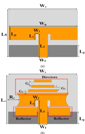
Fig. 1 Geometry of single element patch antenna (a) rectangular patch with inset
(b) with yagi elements and semi-circular etches
For the initial design, a rectangular patch with a simple feedline was designed with insets of size 0.5mm
× 1.25mm made on the rectangular patch as seen in Fig.
1 (a). The ground plane was also reduced to 2.5mm.
Later, semi-circular etch on each sides of patch of radius 2mm were made, reducing the overall size of the patch. Three yagi like directors on top of the patch, and two reflectors on each ends of patch were added. This addition of yagi elements and semi-circular etches improved the directivity along the operating frequency bands and increased the bandwidth to some extent. The geometry of the finalized single element antenna with yagi elements and semi-circular etches is shown in Fig. 1 (b) and dimensions for both are listed in Table 1.
Table. 1 Dimensions of the proposed single element antenna
Parameter mm
Ls × Ws 10 × 12
Lp × Wp 2.75 × 12
Lg 2.5
Lf × Wf 4.875 × 1.6
Li × Wi 1.25 × 0.5
Rc 2
(Reflector) Lr × Wr 1.5 × 3.75 (Directors) Ld × D1, D2, D3 0.5 × 3, 4, 5
G1, G2, G3 0.6, 0.4, 0.2
2.2. Single Element Simulation Results Comparision In this work, study of the antenna is carried by simulation with Ansoft High-Frequency Structure Simulator (HFSS), a commercial electromagnetic simulator.
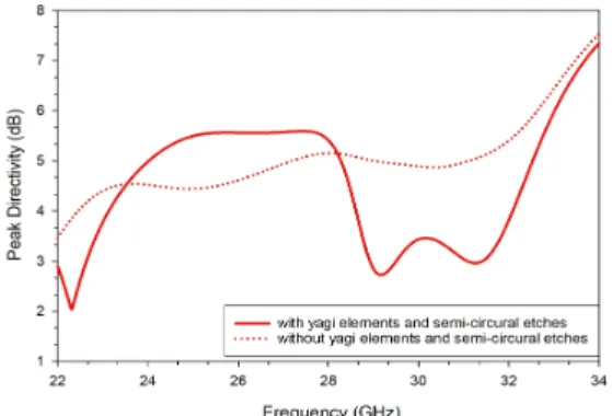
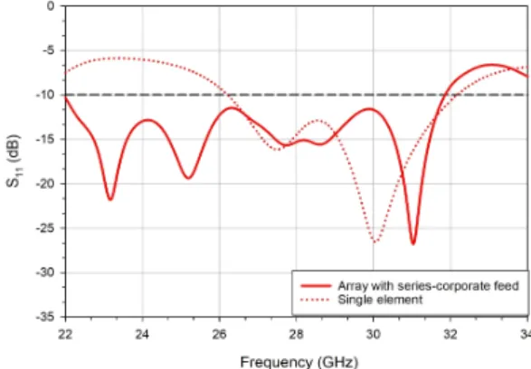
As seen from the simulated results for return loss of single element antenna in Fig. 2, the addition of yagi elements and semi-circular etches has slightly improved the bandwidth (improved from 26.33-31.09 GHz to 26.21-32.16 GHz). Again, in Fig. 3, it can be seen than addition of yagi elements have improved the directivity of antenna in the targeted operating frequency band, with peak directivity of 5.7 dB at 27.5 GHz.
Fig. 2 S11 plot of proposed single element antenna
Fig. 3 Peak directivity of proposed single element antenna
Ⅲ. Array antenna with series-corporate feed
3.1. Array Design
In this paper, rectangular patch array antenna with series-corporate feed is designed. At first, two single element antennas are fed with equal power through a network of microstrip line in the form of T-junction power divider excited by 50 ohm source. Then, two more single element antennas are connected in series using a quarter wavelength transformer making an antenna array. The Yagi elements are placed only above the top elements to achieve directive gain, while reflectors are placed below each single elements in opposite sides only. Overall, the adjusted configuration of feed network as well as optimization in the reflectors and directors have enhanced the performance of antenna, increasing the bandwidth and improving the overall directivity of antenna, suitable for 5G applications.
The width of the main feed that forms a T-junction power divider from 50 ohm source was found using microstrip line design equation [15]. Other parameters of power divider and quarter wavelength transformers were optimized to achieve desirable results. The geometry of the array antenna with series-corporate feed is shown in Fig. 4 and the dimensions are listed in Table 2.
Fig. 4 Geometry of proposed microstrip array antenna with series-corporate feed
Table. 2 Dimensions of the proposed microstrip array antenna with series-corporate feed
Parameter mm
Ls × Ws 23 × 28
Lg 18.5
Lf1 × Wf1 2.5 × 1.9
Lf2 × Wf2 1.6 × 3.5
Lf3 1.9
Wf3 1.6
Lf4 × Wf4 2.55 × 0.2
G 11.48
Rc 2
Lr × Wr 2 × 4
3.2. Microstrip Array Antenna Results
The simulation result in Fig. 5 shows that there is increment in the bandwidth of the antenna when single elements were connected to form an array antenna.
While the return loss of single element showed
bandwidth of 26.21-32.16 GHz, when converted to
array, the bandwidth increased to 21.95-31.86 GHz,
which covers most of the higher 5G bands followed by
different countries [16]. Usually, while designing array
antennas, the single patch elements are combined to
form the final array antenna. Thus, in such cases, the
return loss characteristics of an array antenna and that of
its single patch element is similar. In case of the
proposed design, though most of parameters of single
patch antenna is kept same while designing the array antenna, the placement of Yagi elements in the array antenna is different. While the directors of Yagi elements in single patch antenna is above the patch and two reflectors are placed right below the patch, in array antenna, directors are placed only above patch elements on the top. In addition, the reflectors are placed only on opposite sides of the patch. This is done to reduce the effect of Yagi elements on opposite patch elements.
With this change, positive improvement is seen, as the bandwidth of the antenna is increased from 5.95 GHz (26.21-32.16 GHz) to 9.91 GHz (21.95-31.86 GHz).
Similarly, Fig. 6 shows how the array antenna has higher directivity over the operating band of frequency while compared to that of a single element. The maximum directivity of the single element antenna is 5.6 dB at 27.5 GHz, while that of array antenna is 11.6 dB at 28 GHz. The directivity improved by double when single element antennas were formed into array antenna. The simulated gain and directivity of the array antenna was found to be 9.56 dB and 11.6 dB respectively in E plane for the operating frequency of 28 GHz.
The radiation pattern as seen in Fig. 7 shows the directive nature of the array antenna at 28 GHz.
However, back lobes are also seen in the radiation pattern, which can be reduced in future research.
Ⅳ. CONCLUSION
An efficient antenna array for 5G communication with wide bandwidth covering most of higher 5G bands is proposed in this paper. Good gain and wide bandwidth of 9.91 GHz (21.95-31.86 GHz) was achieved by antenna array. Addition of Yagi elements along with the employment of DGS improved the gain and directivity of the antenna. Thus, the maximum gain of 9.7 dB was achieved along with maximum directivity of 11.6 dB at 28 GHz. Overall, the simulation results proved that the microstrip array antenna’s performance satisfied the requirements of 5G communication.
Fig. 5 S11 of proposed microstrip array antenna with series-corporate feed vs single element
Fig. 6 Peak Directivity of proposed microstrip array antenna with series-corporate feed vs single element
Fig. 7 Radiation pattern of array antenna at 28 GHz
REFERENCES
[ 1 ] T. S. Rappaport, S. Sun, R. M ayzus, H. Zhao, Y. Azar, K.
Wang, G. N. Wong, J. K. Schylz, M. Samimi, and F.
Gutierrez “Millimeter wave mobile communications for 5G cellular: It will work!,” IEEE access, vol. 1, pp. 335–349, May. 2013.
[ 2 ] S. F. Jilani, Q. H. Abbasi, and A. Alomainy, “Inkjet-Printed Millimetre-Wave PET-Based Flexible Antenna for 5G Wireless Applications,” in 2018 IEEE MTT-S International Microwave Workshop Series on 5G Hardware and System Technologies (IMWS-5G), pp. 1–3, 2018.
[ 3 ] Y. Rahayu, and M. I. Hidayat, “Design of 28/38 GHz Dual-Band Triangular-Shaped Slot Microstrip Antenna Array for 5G Applications,” in 2018 2nd International Conference on Telematics and Future Generation Networks (TAFGEN), pp. 93–97, 2018.
[ 4 ] H. A. Diawuo, and Y. B. Jung, “Broadband Proximity- Coupled Microstrip Planar Antenna Array for 5G Cellular Applications,” IEEE Antennas and Wireless Propagation Letters, vol. 17, no. 7, pp. 1286–1290, May. 2018.
[ 5 ] H. Aliakbari, A. Abdipour, R. Mirzavand, A. Costanzo, and P. Mousavi, “A single feed dual-band circularly polarized millimeter-wave antenna for 5G communication,” in 2016 10th European Conference on Antennas and Propagation (EuCAP), pp. 1–5, 2016.
[ 6 ] O. M. Haraz, M. M. M. Ali, S. Alshebeili, and A. R. Sebak,
“Design of a 28/38 GHz dual-band printed slot antenna for the future 5G mobile communication networks,” in 2015 IEEE International Symposium on Antennas and Propagation
& USNC/URSI National Radio Science Meeting, pp. 1532– 1533, 2015.
[ 7 ] H. Errifi, A. Baghdad, A. Badri, and A. Sahel, “Design and analysis of directive microstrip patch array antennas with series, corporate and series-corporate feed network,”
International Journal of Electronics and Electrical Engineering, vol. 3, no. 6, pp. 416–423, Dec. 2015.
[ 8 ] M. A. Sohaib, S. Bashir, S. ur Rehman, and F. Azam, “High gain microstrip yagi antenna for millimeter waves,” in 2018 International Conference on Computing, Mathematics and Engineering Technologies (iCoMET), pp. 1–4, 2018.
[ 9 ] J. S. Park, J. B. Ko, H. K. Kwon, B. S. Kang, B. Park, and D.
Kim, “A tilted combined beam antenna for 5G communications using a 28-GHz band,” IEEE Antennas Wireless Propog. Lett, vol. 15, pp. 1685–1688, 2016.
[10] S. Ershadi, A. Keshtkar, A. H. Abdelrahman, X. Yu, and H.
arrays,” in Proc. Asia
–
Pacific Microw. Conf. (APMC), pp.1–3, Dec. 2015.
[11] H. Aliakbari, A. Abdipour, R. Mirzavand, A. Costanzo, and P. Mousavi, “A single feed dual-band circularly polarized millimeter wave antenna for 5G communication,” in Proc.
10th Eur. Conf. Antennas Propag. (EuCAP), pp. 1–5, Apr.
2016.
[12] Y. X. Guo, K. M. Luk, and K.-F. Lee, “Broadband dual polarization patch element for cellular-phone base stations,”
IEEE Trans. Antennas Propag., vol. 50, no. 2, pp. 251–253, Feb. 2002.
[13] G. Breed, “An introduction to defected ground structures in microstrip circuits,” High Frequency Electron., vol. 11, pp.
50–54, Jul. 2008.
[14] C. A. Balanis, Antenna theory: analysis and design. John Wiley & sons, pp. 811-876, 2005.
[15] D. M. Pozar, Microwave engineering. John Wiley & Sons, pp. 72-75, 2009.
[16] What are 5G frequency bands - RF Page [Internet]. Available:
https://www.rfpage.com/what-are-5g-frequency-bands/.
김영진 (Yeong-Jin Kim)
1998년 8월:조선대학교 전자공학과 석사 2003년 2월:조선대학교 전자공학과 박사 현재 : 조선이공대학교 자동화시스템과 교수
※관심분야 : 네트워크, 무선통신, 안테나 설계 및 해석
자남 마하르잔 (Janam Maharjan)
2014년 Nepal Engineering College, Pokhara University 학사 졸업 2018년 조선대학교 정보통신공학과 석사 졸업 2018년 3월 ~ 현재 조선대학교 정보통신공학과
석사과정
※관심분야 : 5G, 마이크로스트립 패치, MIMO 안테나
최동유 (Dong-You Choi)
1999년 조선대학교 전자공학과 학사 졸업 2001년 조선대학교 전자공학과 석사 졸업 2004년 조선대학교 전자공학과 박사 졸업 2007년 ∼ 현재 조선대학교 정보통신공학과 교수
※관심분야 : 통신 및 전파전파, 전파잡음, 마이크로파 강우감쇠, 안테나 설계 및 해석