1. Introduction
There have been many researches and developments for tracking controller of a surface vessel. It is because
*Corresponding author, E-mail: [email protected] Copyright ⓒ The Korea Institute of Military Science and Technology
that a surface vessel is a useful and suitable device for environmental surveying, seaside monitoring, military landings, and so on [1-5]. Despite its numerous useful applications, there are several challenging problems in the designing of tracking controller; a highly non-linear system models, stabilization, and under-actuated property, that is a system has smaller number of actuators than Research Paper 제어 ․ 구동 부문
슬라이딩 모드 제어와 스위칭 기법에 기반한 수상함의 경로 추종 제어기 설계
이 준 구*,1)
1)국방과학연구소 제6기술연구본부
Path Tracking Controller Design for Surface Vessel Based on Sliding Mode Control Method with Switching Law
JunKu Lee*,1)
1)The 6th Research and Development Institute, Agency for Defense Development, Korea
(Received 1 June 2016 / Revised 11 October 2016 / Accepted 6 January 2017)
ABSTRACT
In this paper, the path tracking controller for a surface vessel based on the sliding mode control (SMC) with the switching law is proposed. In order to have no restriction on movement and improved tracking performance, the proposed control system is developed as follows: First, the kinematic and dynamic models in Cartesian coordinates are considered to solve the singularity problem at the origin. Second, the new multiple sliding surfaces are designed with the SMC and approach angle concept to solve the under-actuated property. Third, the switching control system is designed to improve tracking performance. To prove the stability of the proposed switching system under the arbitrary switching, the Lyapunov stability analysis method with the common Lyapunov function is used. Finally, the computer simulations are performed to demonstrate the performance, effectiveness and stability of the proposed tracking controller of a surface vessel.
Key Words : Surface Vessel(수상함), Tracking Control(추종 제어), Sliding Mode Control(슬라이딩 제어), Switching Control System(스위칭 제어 시스템), Common Lyapunov Function(공통 리아프노프 함수)
degrees of freedom. To solve the problems, many researches have been proposed as follows.
F. A. Papoulias employed the linearized dynamics to design a tracking controller for a surface vessel [1-2], but the proposed controller has the stability problems.
To solve this stability problem, J. M. Godhavn proposed the controller without the linearization of dynamics [6], but it has the errors in tracking. To make up for this fault, the improved tracking controllers were proposed in some researches [3-5], but those also have stability problem in case of a straight trajectory. And to simplify the design process, some researchers used the state transformation method [7] which removes the difficulties caused by the off-diagonal terms of the system matrix.
The dynamic surface control (DSC) technique [8] was also used to solve the explosion of complexity problem caused by the repeated differentiation of virtual controllers in the back stepping design procedure. In addition to the above mentioned methods, lots of methods have been proposed for the tracking controller of a surface vessel [9-18], and H. Ashrafiuon have focused on the Sliding Mode Control (SMC) for designing the tracking controller of surface vessels [19].
In this paper, I propose a method for designing the path tracking controller of a surface vessel based on the SMC with the switching law. In order to remove a movement restriction and improve a tracking performance, the proposed controller is developed as follows: First, the models of AUV, which has similar kinematic and dynamic behavior with an under-acutaed surface vessel on a horizontal plane [21], in the Cartesian coordinates [20] are considered to remove the singularity problem at the origin. And the water flow disturbance is considered to design the practical tracking controller. Next, to solve the under-actuated property of a surface vessel, the new multiple sliding surfaces are designed with approach angle concept. And to improve the tracking performance, the switching system for tracking control is designed with switching algorithm and law [21-25]. For the stability analysis of the proposed switching control system under arbitrary switching, the Lyapunov stability analysis theory with the common Lyapunov function [26-30] is applied.
Finally, the numerical simulations are carried out to demonstrate the performance and effectiveness of the proposed control system.
2. System Modeling
In this chapter, for the kinematic and dynamic models of an under-actuated surface vessel, the models of AUV in the Cartesian coordinates is considered. It is because that AUV presents similar behavior to an under-actuated surface vessel and the AUV model in the polar coordinates has the singularity problem at the origin.
2.1 Kinematic and Dynamic Models
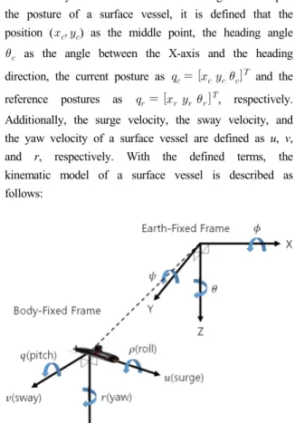
In this paper, the movement of a surface vessel on the horizontal plan is described in the earth fixed frame and the body fixed frame as shown in Fig. 1. To depict the posture of a surface vessel, it is defined that the position ( ) as the middle point, the heading angle
as the angle between the X-axis and the heading direction, the current posture as and the reference postures as , respectively.
Additionally, the surge velocity, the sway velocity, and the yaw velocity of a surface vessel are defined as u, v, and r, respectively. With the defined terms, the kinematic model of a surface vessel is described as follows:
Fig. 1. Earth-fixed and body-fixed frames of system
cos sin
sin cos
(1)
Then the effect of water flow disturbance is considered with the following assumption.
Assumption 1: The water flow disturbance is described two-dimensionally in the earth-fixed frame with a velocity and a direction as follows:
cos sin (2)
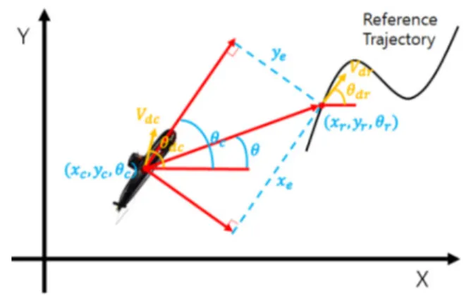
where is the water flow velocity in the X-axis direction, and is the water flow velocity in the Y-axis direction. Since the water flow velocity and direction are not constant, there exist the differences between the disturbance of current and reference position. To apply these disturbance difference to the system model, the following additional terms are defined as shown in Fig. 2.; and are the water flow velocity and direction of current position, and
are the water flow velocity and direction of reference position. With the water flow disturbance, the kinematics of a surface vessel is transformed as follows:
cos sin
sin cos
cos
sin
(3)
Based on the posture error assignment in Fig. 2, the posture error of a surface vessel is derived as follows:
cos sin
sin cos
(4)
By differentiating and transforming (4) with the water disturbance equation and defined terms, the equation for the surge velocity u, the sway velocity v, and the yaw velocity r of a surface vessel is then derived as follows:
Fig. 2. Coordinate assignments for system modeling
cos sin sin cos
cos sin
sin cos
sinsin
coscos
(5)
And the dynamics for a surface vessel is expressed as following differential equations [20] with assumption 2.
Assumption 2: The center of buoyancy coincides with the center of mass, and the mass is distributed homogeneously. The hydrodynamic drag terms, which have higher order than two, heave, pitch, and roll motions can be neglected.
(6)
where , and
Here, and are the combined rigid body and added mass terms , . is the combined rigid body and added mass moment of inertia about the z-axis with the . And , , , , ,
are the linear and quadratic drag coefficients.
In the dynamics of a surface vessel (6), the term denotes the control force along the surge u motion of the body-fixed frame, and denotes the control moment for producing the angular motion around the z-axis of the body-fixed frame. In a surface vessel, there exists no side thruster to control the sway motion v, thus the sway motion is uncontrollable and a surface vessel is an under-actuated dynamic system.
3. Design of Tracking Controller with Switching
In this chapter, the tracking controller for a surface vessel is designed under the consideration of the under-actuated property and stability problems. For the under-actuated property of a surface vessel, the new multiple sliding surfaces are designed with an approach angle concept. Then, based on the proposed reaching law and sliding surfaces, the controllers are designed.
Next, the switching control system is developed with the designed controllers and switching law to improve the tracking performance. Finally, the stability of the proposed control system is proved by using the Lyapunov stability theory with the common Lyapunov function.
3.1 Advanced Reaching Law
Before designing the appropriate sliding surfaces, the reaching law is designed to makes the states converge to the proposed sliding surfaces with the condition as follows:
∙ for any t (7)
Here, to satisfy the above condition, the reaching law is typically chosen as follows:
∙
(8)
where K is the positive constant. From the above
reaching law, the reaching time , the necessary time for each state to converge to the sliding surface, is derived as follows:
(9)
According to (9), as K values increases, the reaching time decreases. However, large K value increases the chattering phenomenon and tracking errors, and those worse the tracking performance. In order to improve the tracking performance, this paper considered the following reaching law;
(10)
where , and are the positive constant, is the strictly positive offset which is less than 1. , are strictly positive integers. With the above conditions, R(S) is always strictly positive.
Therefore, R(S) does not affect the stability of controller.
In the reaching law (10), as increases, R(S) converges to , and consequently converges to , which is smaller than with large value. It means that each state converge to the proposed sliding surface faster. On the other hand, as decreases, R(S) converges to , and consequently the reaching law gradually decreases, which decreases the chattering phenomenon and the tracking errors. Therefore, the reaching law (10) is suitable to improve tracking performance of controller.
3.2 Sliding Surface with Approach Angle
In order to make a surface vessel follow the trajectory, the controller needs to make the posture error ( ) converge to zero as time elapses. To do this, the approach angle concept, respect to the defined coordinate as shown in Fig. 2, is applied. From Fig. 2, it is verified that converges to zero as the heading
angle converges to an approach angle . Since the heading angle is tangential to the reference trajectory, the heading angle error converges to zero as a surface vessel follows the reference trajectory exactly.
Therefore, the posture error ( ) converges to zero as and converge to zero. Then, the sliding surface with the first order filters is defined as follows:
(11)
tan
where . Based on the first order filter property, as and converge to zero, and converge to zero. In addition, the sliding surfaces (11) have different properties according to the values of and . With the large and values, each state converge to the sliding surface rapidly. And the small
and values allows each state converge to the sliding surface with small chattering phenomenon. Based on this property, the multiple sliding surfaces
⋯ which have different values of and are designed as follows:
(12)
where ≠ ≠⋯≠ and ≠ ≠⋯≠
. Then, by using the multiple sliding surfaces which have the different properties, the advanced tracking controller can be designed.
3.3 Control Law Design for Surface Vessel
The sliding surfaces ⋯ have a similar form, only have different values of and , therefore the each controller for the proposed multiple sliding surfaces can be designed in the same method. Then, to design the appropriate control law for each sliding
surfaces, I substitute (1) and (5) into each differentiated sliding surface as follows:
cos sin
sincoscos
cossinsin
(13)
Then, by substituting (11) and (13) into (7), the control input for sliding surface is obtained as follows:
(14)
In a surface vessel, only and are the controllable inputs, thus the control input for sliding surface is derived from (6) and (14) as follows:
(15)
where and are the control input values of . Here each controllers have the different control input
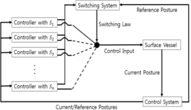
based on the sliding surface . To operate those multiple controllers as the one unit controller, the switching algorithm for the tracking control of a surface vessel is proposed as shown in Fig. 3.
Fig. 3. Switching algorithm for control system
Based on the current posture , the reference posture
, and the sliding surface S, each controllers generates the appropriate control inputs which have different control properties. To use those multiple controllers efficiently, the proposed switching system estimates the posture errors with each control input as follows:
(16)
where are the estimated current posture with the control input , and are the positive constant to weight importances for each error. With the defined switching law and control inputs, the control input is designed as follows:
∙ ∙ ⋯ ∙ (17)
where when smallest, else for ∈ ⋯ .
3.4 Stability Analysis with Common Lyapunov Function
In the switching system, the stability analysis under the arbitrary switching is one of the most difficult problems because even when all the controllers of switching system are exponentially stable, it is still possible that the overall system can be unstable for a certain switching signals. Thus, it is necessary to show the stability of switching system under the arbitrary
switching, and to do so, the common Lyapunov function (CLF) method is used in this paper. It is because if there exists CLF for all its controllers and systems, then the stability of switching system is guaranteed under arbitrary switching.
Theorem: The control input (17) stabilizes the overall tracking control system under Assumption 1 and 2.
Thus, the posture errors converge to zero.
Proof: In order to show the existence of CLF for the proposed switching system, the Lyapunov function selected as follows:
∈ ⋯for all non-zero matrix (18)
where V is positive definite. To prove the stability of the controllers with the Lyapunov function V, (13) and (15) are substituted as follows:
cos sin
sincoscos
cossinsin
cos
sin
sincos cossin
sincos cossin
(19)where ∈ ⋯ Since the Lyapunov function V is positive definite and is negative definite regardless, it is proven that all controllers are stable by the Lyapunov function stability theory with CLF, and the proposed switching system is stable under arbitrary switching.
Based on the above results, the proposed switching system for a tracking control of a surface vessel makes the posture error converge to zero stably with the control input.
4. Simulation Results
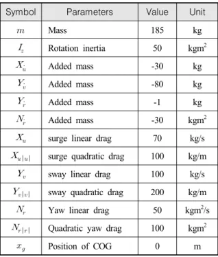
In this chapter, the simulation results for the given reference trajectories are presented to demonstrate the performance of the proposed controller for a surface vessel. For the simulations, the rigid body and hydrodynamic parameters [20] are selected as Table 1.
Table 1. Hydrodynamic parameters
Symbol Parameters Value Unit
Mass 185 kg
Rotation inertia 50 kgm2
Added mass -30 kg
Added mass -80 kg
Added mass -1 kg
Added mass -30 kgm2
surge linear drag 70 kg/s
surge quadratic drag 100 kg/m
sway linear drag 100 kg/s
sway quadratic drag 200 kg/m
Yaw linear drag 50 kgm2/s
Quadratic yaw drag 100 kgm2
Position of COG 0 m
The initial conditions are selected as =
and . Then, the control parameter values are chosen as follows:
For the water flow disturbance of a surface vessel, the current direction and velocity is designed as follows:
sin
sin
sin
sin
sin
cos
sin
cos
(20)
where , , have minimum
and maximum 70° values. With the water flow equation and parameters, the disturbances are generated as shown in Figs. 4 and 5.
Fig. 4. Water flow velocity in X-axis direction
Fig. 5. Water flow velocity in Y-axis direction
Then, to investigate the stability and performance of the proposed controller for a surface vessel, the values for the multiple sliding surfaces and reference condition are selected as follows:
Condition : For a complicated line, the linear, angular, surge, and yaw velocities of reference trajectory are selected as follows:
≤ ≤
≤ ≤
≤ ≤
≤ ≤
≤ ≤
Then, to confirm the performance and stability of the proposed switching control system, the simulations are performed with different number of sliding surfaces as follows.
Fig. 6. Tracking control result of the proposed control system with sliding surfaces ~
Fig. 7. Switching law result with ~
Fig. 6 depicts the tracking control result of proposed switching control system with sliding surfaces ~. As shown in Fig. 6, a surface vessel stably and exactly follows the given reference trajectory from the origin
Fig. 8. Tracking errors with sliding surfaces ~
Fig. 9. Tracking errors with sliding surface
Fig. 10. Tracking errors with sliding surfaces ~
point, without a singularity problem. Figs. 7 and 8 show switching law result and the tracking errors while a surface vessel follows the given reference trajectory. Fig.
7 shows that the proposed system selects an appropriate controller from the multiple controllers based on the switching algorithm and law. And Fig. 8 shows that the posture errors converge to zero in short time with very small tracking errors and chattering phenomenon. Based on the Figs. 6-8, it is verified that the proposed control system is stable under arbitrary switching with remarkable tracking performance. And Fig. 9 depicts the tracking control result with only one controller (based on ), and it shows a large tracking errors. Fig. 10 is with two controllers (based on and ) and shows that the additional controller decreases the tracking errors. And by comparing Figs. 8-10, it is proved that the switching system with multiple controllers improves the tracking performance of proposed control system.
From the simulation results, I verify that the proposed switching control system for surface vessel tracking is stable under arbitrary switching, and make a surface vessel exactly follow the given reference trajectory with the decreased reaching time, tracking errors, and chattering phenomenon.
5. Conclusion
In this paper, a method for designing the path tracking controller for a surface vessel based on the sliding mode control with the switching law is proposed.
In order to have no restriction on movement and improved tracking performance, the proposed controller is developed as follows:
First, the kinematic and dynamic model equations in the Cartesian coordinates are considered because the kinematic model in the polar coordinates has the singularity problem at the origin. In addition, the water disturbance is considered to design the practical tracking controller of a surface vessel. Second, in order to solve the under-actuated property, the new multiple sliding surfaces are design by using the SMC with an approach angle. Third, the switching system for tracking control is
designed by connecting the multiple controllers with the switching algorithm and law to improve the tracking performance. To prove the stability of the proposed switching control system under the arbitrary switching, the Lyapunov stability analysis method with the common Lyapunov function is used. Finally, the numerical computer simulations are performed to demonstrate the performance and effectiveness of the proposed tracking control system of a surface vessel. From the simulation results, it is verified that the proposed tracking control system is stable under the arbitrary switching, and has the improved tracking performance.
References
[1] F. A. Papoulias and Z. Oral, “Hopf Bifurcation and Nonlinear Studies of Gain Margins in Path Control of Marine Vehicles,” Applied Ocean Research, Vol.
17, No. 1, pp. 21-32, 1995.
[2] F. A. Papoulias, “Cross Track Error and Proportional Turning Rate Guidance of Marine Vehicles,” Journal of Ship Research, Vol. 38, No. 2, pp. 123-132, 1994.
[3] K. Y. Pettersen and H. Nijmeijer, “Underactuated Ship Tracking Control : Theory and Experiments,”
Int. Jour. of Control, Vol. 74, No. 14, pp. 1435-1446, 2001.
[4] Z. P. Jiang, “Global Tracking Control of Underactuated Ships by Lyapunov's Direct Method,”
Automatica, Vol. 38, No. 1, pp. 301-309, 2002.
[5] E. Lefeber, K. Y. Pettersen and H. Nijmeijer,
“Tracking Control of an Underactuated Ship,” IEEE Trans. Control Systems Technology, Vol. 11, No. 1, pp. 52-61, 2003.
[6] J. M. Godhavn, T. I. Fossen and S. Berge,
“Nonlinear and Adaptive Back Stepping Design for Tracking Control of Ships,” Int. Jour. of Adaptive Control and Signal Processing, Vol. 12, No. 8, pp.
649-670, 1998.
[7] K. K. Do, “Practical Control of Underactuated Ships,”
Ocean Engineering, Vol. 37, No. 13, pp. 1111-1119, 2010.
[8] D. Swaroop, J. K. Hedrick, P. P. Yip and J. C.
Gerdes, “Dynamic Surface Control for a Class of Nonlinear Systems,” IEEE Trans. Automatic Control, Vol. 45, No. 10, pp. 1893-1899, 2000.
[9] L. Lapierre and D. Soetanto, “Nonlinear Path- Following Control of an AUV,” Ocean Engineering, Vol. 34, No. 11-12, pp. 1734-1744, 2007.
[10] Y. Kim, J. Lee, S. Park, B. Jeon and P. Lee “Path Tracking Control for Underactuated AUVs Based on Resolved Motion Acceleration Control,” Proc. of Conference on Autonomous Robots and Agents, Wellington, New Zealand, pp. 342-346, 2009.
[11] B. He and Z. Zhou, “Path Planning and Tracking for AUV in Large-Scale Environment,” Proc. of Asia Conf. on Information in Control, Automation and Robotics, Wuhan, China, pp. 318-321, 2010.
[12] B. Subudhi and D. Atta, “Design of a Path Following Controller for an Underactuated AUV,”
Archives of Control Sciences, Vol. 19, No. 3, pp.
245-259, 2009.
[13] F. Repoulias and E. Papadopoulos, “Planar Trajectory Planning and Tracking Control Design for Underactuated AUVs,” Ocean Engineering, Vol.
34, No. 11-12, pp. 1650-1667, 2007.
[14] K. D. Do, “Practical Formation Control of Multiple Underactuated Ships with Limited Sensing Ranges,”
Robotics and Autonomous Systems, Vol. 59, No. 6, pp. 457-471, 2011.
[15] E. Yang and D. Gu, “Nonlinear Formation-Keeping and Mooring Control of Multiple Autonomous Underwater Vehicles,” IEEE Trans. Mechatronics, Vol. 12, No. 2, pp. 164-178, 2007.
[16] R. Skjetne, S. Moi and T. Fossen, “Nonlinear Formation Control of Marine Craft,” Proc. of IEEE Conference Decision and Control, pp. 1699-1704, Las Vegas, 2002.
[17] Z. S. Mi and Y. G. Kim, “Intelligent 3D Obstacles Recognition Technique Based on Support Vector Machines for Autonomous Underwater Vehicles,”
International Journal of Fuzzy Logic and Intelligent Systems, Vol. 9, No. 3, pp. 213-218, 2009.
[18] Y. H. Choi and K. J. Kim, “Robust Path Tracking Control for Autonomous Underwater Vehicle with Variable Speed,” Journal of The Korean Institute of
Intelligent Systems, Vol. 20, No. 4, pp. 476-482, 2010.
[19] H. Ashrafiuon, K. R. Muske, L. C. McNinch and R. A. Soltan, “Sliding Mode Tracking Control of Surface Vessels,” IEEE Trans. Industrial Electronics, Vol. 55, No. 11, pp. 4004-4012, 2008.
[20] F. Repoulias and E. Papadopoulos, “Planar Trajectory Planning and Tracking Control Design for Underactuated AUVs,” Ocean Engineering, Vol.
34. No. 11, pp. 1650-1667, 2007.
[21] A. Pedro Aguiar and M. Pascoal Antonio, “Dynamic Positioning and Way-Point Tracking of Underactuated AUVs in the Presence of Ocean Currents,”
International Journal of Control, Vol. 80. No. 7, pp.
1092-1108, 2007.
[22] N. R. Gans and S. A. Hutchinson, “Stable Visual Serving Through Hybrid Switched-System Control,”
IEEE Trans. Robotics and Automation, Vol. 23.
No. 3, pp. 530-540, 2007.
[23] V. Sankaranarayanan and A. D. Mahindrakar
“Switched Control of a Nonholonomic Mobile Robot,” Commun Nonlinear Science Numerical Simulation, Vol. 14, No. 5, pp. 2319-2327, 2009.
[24] A. S. Morse, “Supervisory Control of Families of Linear Set-Point Controllers Part I. Exact Matching,”
IEEE Trans. Automatic Control Vol. 41, pp. 1413- 1431, 1996.
[25] S. R. Kulkarni and P. J. Ramadge, “Model and Controller Selection Policies Based on Output Prediction Errors,” IEEE Trans. Automatic Control, Vol. 41, pp. 1594-1604, 1996.
[26] K. S. Narendra and J. Balakrishnan, “Adaptive Control using Multiple Models,” IEEE Trans.
Automatic Control, Vol. 42, pp. 171-187, 1997.
[27] D. Liberzon and A. S. Morse, “Basic Problems in Stability and Design of Switched System,” IEEE Control Systems, Vol. 19, No. 5, pp. 59-70, 1999.
[28] DeCarlo, Raymond A. and et al., “Perspectives and Results on the Stability and Stabilizability of Hybrid Systems,” Proceedings of the IEEE, Vol. 88, No. 7, pp. 1069-1082, 2000.
[29] Liberzon, Daniel, Joao P. Hespanha, and A. Stephen Morse, “Stability of Switched Systems : A Lie-
Algebraic Condition,” Systems & Control Letters, Vol. 37, No. 3, pp. 117-122, 1999.
[30] Z. He, S. Zhang, and J. Wu, “Sliding Mode Control of Switched Linear Systems Based on Common Lyapunov Function,” Proc. of the 3rd Int. Symp.
on Systems and Control in Aeronautics and Astronautics, Vol. 1, pp. 300-304, 2010.
[31] O. M. A. Al-Ola, K. Fujimoto and T. Yoshinaga,
“Common Lyapunov Function Based on Kullback- Leibler Divergence for a Switched Nonlinear
System,” Mathematical Problems in Engineering, Vol. 1, pp. 1-12, 2011.
[32] W. Gao and J. C. Hung, “Variable Structure Control of Nonlinear Systems : A New Approach,” IEEE Trans. Ind. Electron., Vol. 40, No. 1, pp. 45-55, 1993.
[33] C. J. Fallaha, M. Saad, H. Y. Kanaan, and K. A.
Haddad, “Sliding Mode Robot Control with Exponential Reaching Law,” IEEE Trans. Ind.
Electron., Vol. 58, No. 2, pp. 600-610, 2011.