Mechanical Modeling of Rollable OLED Display Apparatus Considering Spring Component
Boo Soo Ma, Woosung Jo, Wansun Kim, and Taek-Soo Kim†
Department of Mechanical Engineering, Korea Advanced Institute of Science and Technology (KAIST), 291, Daehak-ro, Yuseong-gu, Daejeon 34141, Korea
(Received June 1, 2020: Corrected June 19, 2020: Accepted June 28, 2020)
Abstract: Flexible displays have been evolved into curved, foldable, and rollable as the degree of bending increases.
Due to the presence of brittle electrodes (e.g. indium-tin oxide (ITO)) that easily cracked and delaminated under severe bending deformation, lowering mechanical stress of the electrodes has been critical issue. Because of this, mechanical stress of brittle electrode in flexible displays has been analyzed mostly in terms of bending radius. On the other hand, in order to make rollable display, various mechanical components such as roller and spring are needed to roll-up or extend the screen for the rollable display apparatus. By these mechanical components, brittle electrode in the rollable display is subjected to the excessive tensile stress due to the retracting force as well as the bending stress by the roller. In this study, mechanical deformation of rollable OLED display was modeled considering boundary conditions of the apparatus. An analytical modeling based on the classical beam theory was introduced in order to investigate the mechanical behavior of the rollable display. In addition, finite element analysis (FEA) was used to analyze the effect of mechanical components in the apparatus on the brittle electrode. Furthermore, a strategy for improving the mechanical reliability of the rollable display was suggested through controlling the stiffness of adhesives in the display panel.
Keywords: rollable display, finite element analysis, retracting force, indium tin oxide, soft adhesive
1. Introduction
In recent years, flexible displays have been spotlighted in the display industry due to versatile applications and the great market potential. However, the commercialization of flexible displays has been faced with troubles related to mechanical reliability. Organic light emitting diodes (OLED) that are primarily used in flexible displays contain brittle oxides for passivation layer and electrode such as indium-tin oxide (ITO).1,2) When the flexible display is subjected to severe bending deformation during operations, the brittle materials are easily cracked or delaminated even at small deformation, causing significant reliability prob- lems such as performance drop and device degradation.3-5) In order to improve the mechanical reliability of flexible displays, there have been many studies on bending stress of the display panel. Analytical modeling for flexible OLED display has been generally considered as composite beam. 6-7) Numerical analysis also has been performed to locate brittle layers on the neutral axis, where the bending
stress become zero, under the bending conditions by con- trolling thickness and elastic modulus of the various com- ponents in the flexible OLED.8,9) In addition, protecting several brittle layers away from each other (e.g. hard coat- ing, encapsulation) has been demonstrated using formation of multiple neutral axes by large deformation of soft adhe- sives in flexible OLEDs.24,25) However, previous works considered the stress of brittle layers only under the bend- ing loading conditions. Therefore, these strategies for flex- ible displays are limited to the bendable displays, despite the potential of flexible displays that can be advanced other complex form such as a rollable display.
Rollable display can realize a large screen even with a small volume of device, which the display panel is rolled up to cylindrical roller.10) In the rollable display apparatus, a spring component is used to generate retracting force to roll up the extended display panel. When the display panel is in a rolled state, the rolled display is subjected to bend- ing stress corresponding to the curvature of the roller. In order to extend the screen, the display panel is pulled out
†Corresponding author E-mail: [email protected]
© 2020, The Korean Microelectronics and Packaging Society
This is an Open-Access article distributed under the terms of the Creative Commons Attribution Non-Commercial License(http://creativecommons.org/
licenses/by-nc/3.0) which permits unrestricted non-commercial use, distribution, and reproduction in any medium, provided the original work is properly cited.
20 Boo Soo Ma, Woosung Jo, Wansun Kim, and Taek-Soo Kim
from the apparatus by pulling the handle. In this state, both the roller and the spring components simultaneously apply geometrical constraint and retracting force to the extended display panel.11,12) Furthermore, interactions such as self- contact of display panel or contact between display panel and roller surface also occur on the rollable display panel.
Therefore, it is essential to consider these boundary condi- tions in the apparatus for mechanical modeling of the rolla- ble display. However, there has been no study on the mechanical analysis of brittle layers considering complex boundary conditions of the rollable display apparatus.26)
In this study, mechanical deformation of the brittle elec- trode in rollable OLED display is analyzed by analytical modeling and numerical analysis with consideration of boundary conditions in the rollable display apparatus. Ana- lytical model of the rollable display is validated by com- paring with finite element analysis (FEA). Then, the effects of the various factors such as the spring and number of rev- olutions on the mechanical deformation of the display panel are analyzed. Moreover, controlling compliance of adhesive layers in the OLED panel using shear lag phe- nomenon has been proposed as a strategy to improve mechanical reliability of the rollable display.
2. Methods
2.1 Finite Element (FE) Modeling
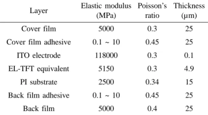
In order to analyze the mechanical behavior of rollable display panel, the FE modeling was conducted using a nonlinear static solver in ABAQUS 6.14, which is com- mercial FEA software. As shown in Fig. 1(a), the cross- sectional 2D structure of the display panel was modeled as a deformable solid.27) The handle and the roller were mod- eled as a rigid body. The mechanical properties of each layer were listed in Table 1.6-9, 13-16) Each side of the back film in the display panel 65 mm long was bonded by tie
constraint to the roller with a radius of 10 mm and the han- dle, respectively (Fig. 1(b)). The spring component was assumed as a linear and rotational connector, which is coaxially connected to the roller. The display panel was discretized to eight-node biquadratic plane strain elements (CPE8R) for each layer.
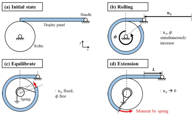
The analysis was performed in 3 steps to reflect the boundary conditions of the rollable display apparatus. The detailed boundary conditions at each step were explained in Fig. 2. At the initial state, the display panel was flat and in a stress-free state. Next, the handle is moved simultane- ously with the rotation of the roller and the spring compo- nent (Fig. 2(b)). Because rotation of the roller without movement of the handle causes the panel to fold without rolling due to the bending stiffness of the display panel.
The spring component was rotated as same angle with the roller because the retracting force by the spring should be zero in the rolled state. Next, rotation constraint of roller is released before the screen extension, and force equilibrium between spring, roller, and the display panel occurs to allow the roller to rotate freely (Fig. 2(c)). The handle is fixed while the rotation of the roller was not constrained, because the roller should be rotated freely before the screen extension. At the 3rd step, the handle returns to its position in the initial state in order to extend the screen (Fig. 2(d)).
As the handle is moved, the roller is also rotated and the spring component exerts retracting force on the display panel. In this study, we mainly analyzed strain of the ITO electrode, which is most brittle than other layers in the dis- play structure, at the 3rd step that the rolled screen is fully extended by retracting force of the spring component.
2.2 Analytical Modeling
In order to understand the mechanical behavior of rolla- ble displays, a simplified analytical model is constructed.
As shown in Fig. 3, the OLED display panel can be assumed to be a long and thin laminated plate, which con-
Fig. 1. (a) Structure of rollable display panel, (b) overall view of rollable display in FE modeling.
Table 1. Mechanical properties of each layer in rollable display panel
Layer Elastic modulus (MPa)
Poisson’s ratio
Thickness (µm)
Cover film 5000 0.3 25
Cover film adhesive 0.1 ~ 10 0.45 25
ITO electrode 118000 0.3 0.1
EL-TFT equivalent 5150 0.3 4.9
PI substrate 2500 0.34 15
Back film adhesive 0.1 ~ 10 0.45 25
Back film 5000 0.4 25
sists of n layers without any patterns or bumps,6) and one end of the display panel should be connected to the roller in the rollable display apparatus. Firstly, the display panel is rolled up to the roller before the screen extension. In this state, the display panel is basically subjected to the bending stress by the roller. However, when the screen is extended,
the roller is rotated in the direction of the screen extension.
Then, the spring component, which is connected to the roller in series, will be also distorted and provide the retracting force that helps to return the display panel to the rolled state.11) In other words, when the screen is in the extended state, the tensile stress due to the retracting force of the spring also acts on the display panel in addition to the bending stress caused by the roller. Consequently, the mechanical stress of the rollable display can be expressed by the sum of the bending stress and tensile stress caused by the roller and the spring component, respectively.
The equation for the mechanical strain applied to the brittle layer is derived as below. For consistency with other studies on fracture behavior of ITO electrode,3,9,24) the equation for strain was derived instead of stress of the brit- tle layer. Since the display panel is long and thin, a plane strain condition can be assumed for the xy plane.7) Without screen extension, the display panel is rolled up to the roller which have radius (R). In this state, the bending stress and strain of the mth layer in the display panel can be expressed as follows, respectively:8)
(1)
where εb,m is bending strain, σb,m is bending stress, Em = E/
(1 υ2m) is plane strain modulus, and ym is height of the brittle layer. y is height of neutral axis for pure bending state. Through this equation, it is confirmed that the bend- Fig. 3. Free body diagram of rollable display panel in rollable
display apparatus.
Fig. 2. Boundary conditions of rollable display for each steps in FE modeling. (a) Initial state, (b) 1st step for rolling the display panel, (c) 2nd step for connecting the spring to the roller, and (d) 3rd step for pulling the handle to the position in initial state.
22 Boo Soo Ma, Woosung Jo, Wansun Kim, and Taek-Soo Kim
ing strain of the brittle layer is determined by bending radius, thickness and plane strain modulus of the films.
When the screen is extended, display panel is unrolled by a length (L), and the retracting force is applied to the display panel by the distortion of the spring component.
The sum of all moment acting on the display panel becomes zero with consideration of the reference center.
The normal force to the display panel applied by the roller is canceled in the moment equilibrium by selecting the ref- erence center as center axis of roller (O).
When the friction of roller surface and the force perpen- dicular to the direction of the screen extension are negligi- ble, summation of the moments about the center axis O is expressed as follows:
(2)
Where Mspring is the moment by the spring component, F is a pulling force in the direction of the screen extension. If we assume that the moment by the spring component is proportional to the distorted angle of the spring (θ), the moment can be expressed as Mspring = kθ. Since the amount of deformation of the display will be much smaller than the rotation of the roller, it can be assumed that the extended length L is geometrically equal to the arc length of the bending radius with respect to the distorted angle of the spring and the roller (θ).
(3)
where k is spring constant of the spring component. By combining equation (2) and (3), the pulling force (F) can be expressed as kL/(R +ni=1hi/2)2, which is a function of L and k. Since the display panel is subjected to the pulling force along the direction of the screen extension, additional tensile strain (εs) is uniformly applied to the cross-sectional area of the display panel.
(4)
where Ai is the cross-sectional area of the ith layer, and w is width of the display panel. Finally, when the screen is extended, the strain of the brittle mth layer (εextended,m) is equal to the summation of the bending strain by the roller and the additional tensile strain by the spring as follows:
(5)
In equation (5), the strain of the brittle layer has linear relationship with the spring constant and the extended length. It means that the more the screen is extended, the higher tensile strain will be applied to the brittle layer in the rollable display. Moreover, both εb,m and εs have a neg- ative correlation with the radius of the roller. In other words, if the rollable display apparatus is miniaturized to a mobile phone, severe tensile strain can be applied to the brittle layers. Therefore, in order to improve mechanical reliability of rollable display, additional tensile strain by retracting force of the spring component should be consid- ered as well as the bending strain by the roller.
3. Results & Discussion
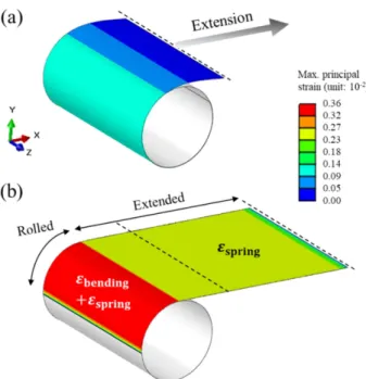
The FEA results were visualized in 3 dimensions by extrusion of the display panel width as shown in Fig. 4(a) and (b), due to the thin display panel which make hard to visualize strain distribution. Before the screen extension, maximum strain of ITO electrode was 0.11%, which was equal to the analytical bending strain calculated using equation (1). This indicates that the display panel is sub- jected to a bending strain corresponding to the radius of the roller before the screen extension. When the screen started to extend, the maximum strain of the ITO electrode increased as the extended length increased. For example, at the extended length is 35 mm, strain distribution of ITO electrode was plotted in Fig. 5(a). In the extended portion,
Fig. 4. FEA result of strain distribution for ITO electrode (a) before the screen extension and (b) after the screen extension (Extended length = 35 mm).
strain of ITO electrode was 0.23%, which was equal to the strain by the spring component (εs, εspring) calculated using equation (4). In particular, the strain of ITO electrode within the rolled portion (0.35%) was nearly equal to the summation of the analytical bending strain (εb,ITO, εbending,ITO) and the tensile strain by the spring component. It means that the strain of ITO electrode was maximized at the rolled portion by overlap of both the bending strain by the roller and the additional tensile strain by the spring. Maxi- mum strain of ITO electrode as a function of extended length was plotted in Fig. 5(b). The strain of ITO electrode analyzed by FE modeling was in good agreement with the analytical modeling. Both modeling represented that the maximum strain of ITO electrode has linear relationship with the extended length of the screen due to the retracting force by the spring component. Therefore, not only the bending strain by the roller, but also tensile strain by the spring component should be reduced to protect brittle ITO electrode in the rollable display. We also investigated the change in strain of ITO electrode as the number of revolu- tions increase with the same spring constant (Fig. 5(c)). To model the case in which the display panel is rolled up 2 revolutions, length of the display panel increased from 65 mm to 130 mm. Before extending the screen, strain of ITO electrode in case of 2 revolutions (0.14%) was slightly higher than that of 1 revolution (0.11%). When the display panel was rolled up 2 revolutions to the roller, the maxi- mum strain of ITO electrode increased to 0.98%, which is nearly twice higher than that of 1 revolution (0.43%) and slightly higher than that of analytical result (0.87%). This implies that increasing the screen size could greatly affect the deformation of the brittle electrode. Thus, other method to protect brittle layers in the display panel is also required as well as optimizing the factors in the rollable display apparatus such as the spring component and the screen size.
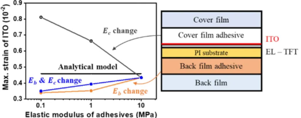
Protection of brittle layers in flexible devices has been shown by using adhesives, which have low elastic modu- lus.21,22) These studies were based on the principle of decoupling the strain distribution of the adjacent stiff layers by inducing large shear deformation of the soft adhe- sive.17-20) We investigated whether the protection method by using soft adhesives were applicable to the rollable dis- play apparatus. Elastic modulus of cover film adhesive and back film adhesive was changed by referring to the general elastic modulus of the adhesives used in the flexible OLEDs.13-16) Since there are two adhesive layers in the rol- lable display panel, the elastic modulus of each or both were controlled. As shown in Fig. 6, when the elastic mod-
ulus of both adhesives were reduced to 0.1 MPa, the strain of ITO electrode was 0.35%, while the analytical value was almost constant at 0.46%. This difference between FEA and analytical results was caused by the large shear defor- mation of the soft adhesive, which results in the decoupling of strain distribution of the display panel. In the conven- tional beam theory, it has been known that bending strain is linearly distributed in the thickness direction.23) In particu- lar, as can be seen from equation (1), the adhesive has little influence on the analytical strain of ITO electrode because the elastic modulus of the adhesive is significantly low compared to the other layers. However, if a compliant layer is placed between adjacent stiff layers, the compliant layer will experience severe shear deformation, resulting in the strain decoupling between the stiff layers. Fig. 7 shows the Fig. 5. (a) Strain distribution of ITO electrode at the extended length = 35 mm. (b) Maximum strain of ITO electrode as a function of the extended length of screen. (c) Effect of number of revolutions of display panel on maximum strain of ITO electrode.
24 Boo Soo Ma, Woosung Jo, Wansun Kim, and Taek-Soo Kim
strain distribution of cross-section in rolled portion of the display panel when the extended length is 48 mm. When both the elastic modulus of the back film adhesive (Eb) and the cover film adhesive (Ec) were 10 MPa, the strain distri- bution in the cross-section of the display panel was almost linear (Bold black line in Fig. 7(a)). In contrast, if the elas- tic modulus of one or both adhesive layers were softened to 0.1 MPa, the strain distribution was decoupled as shown in Fig. 7(b), (c) and (d). In addition, when the Eb = 0.1 MPa, Ec = 0.1 MPa, and both Eb and Ec = 0.1 MPa, the shear strain (γ) of softened adhesive layers were γb = 0.76 rad, γc
= 1.13 rad, γb = 0.65 & γc = 1.09 rad, respectively. These shear strain values were significantly larger than the other stiff layers (~ 0.0005 rad), such as cover film and back film. It means that the strain distribution in the display panel is decoupled by inducing a large shear deformation
of the soft adhesive due to the shear lag phenomenon.19-21) Therefore, the protection of brittle layer by using soft adhe- sives can be apply to the rollable display apparatus even if the effect of the spring component is present. However, when the elastic modulus of cover film adhesive was soften to 0.1 MPa while fixing the elastic modulus of back film adhesive (10 MPa), the strain of ITO electrode dra- matically increased to 0.81% (Fig. 7(b)) In this case, cover film adhesive induces strain decoupling between the cover film and the other layers which have a linear strain distri- bution in the thickness direction. Therefore, ITO electrode is located at the outermost of the coupled layers, resulting in the largest strain. This implies that coupling the strain distribution of the layers below the ITO electrode can cause severe deformation of the ITO electrode. In conclu- sion, the brittle layer in the rollable display should be pro- Fig. 6. Effect of elastic modulus of two adhesives in display panel on maximum strain of ITO electrode.
Fig. 7. FEA result of strain distribution and cross-sectional view of rolled portion in display panel (Extended length = 48 mm). (a) When both Ec and Eb = 10 MPa, (b) Ec = 0.1 MPa and Eb = 10 MPa, (c) Ec = 10 MPa and Eb = 0.1 MPa, (d) both Ec and Eb = 0.1 MPa.
tected from mechanical fracture considering strain decoupling between the layers.
4. Conclusion
Mechanical behavior of rollable OLED display was investigated by using analytical modeling and numerical analysis with consideration of the boundary conditions of the apparatus. The brittle electrode in the display panel was subjected not only the bending strain by the roller but also additional tensile strain due to the retracting force of the spring component. It was also identified that the mechani- cal strain of the brittle electrode has a linear relationship with the extended length of the screen. Moreover, the effects of spring and number of revolutions on the brittle electrode were investigated to reduce the tensile strain of the electrode in the rollable display. From the results, it was confirmed that the strain of the brittle electrode can be low- ered by optimizing stiffness of the spring component and extension length of the screen. Furthermore, the strain of the brittle electrode could be lowered by controlling com- pliance of the adhesives, which are sandwiched between cover and back films in the display panel. In conclusion, our works provide essential guidance to improve mechani- cal robustness of the display panel for commercialization of the rollable display apparatus.
Acknowledgements
This work was supported by the Wearable Platform Materials Technology Center (WMC) funded by the National Research Foundation of Korea(NRF) Grant by the Korean Government(MSIT) (No. 2016R1A5A1009926), and Korea Institute of Energy Technology Evaluation and Planning (KETEP) and the Ministry of Trade Industry &
Energy (MOTIE) of the Republic of Korea (No. 201830 10014470).
References
1. P. C. P. Bouten, P. J. Slikkerveer, and Y. Leterrier, “Mechanics of ITO on Plastic Substrates for Flexible Displays”, Flexible flat panel displays, 20(1), 99 (2005).
2. J. Lewis, “Material challenge for flexible organic devices”, Mater. Today, 9(4), 38 (2006).
3. Y. Leterrier, L. Medico, F. Demarco, J.-A.E. Månson, U. Betz, F. M Escola, M. Kharrazi Olsson, and F. Atamny, “Mechan- ical integrity of transparent conductive oxide films for flexible polymer-based displays”, Thin Solid Films, 460(1-2), 156 (2004).
4. Z. Jia, M. B. Tucker, and T. Li, “Failure mechanics of
organic–inorganic multilayer permeation barriers in flexible electronics”, Compos. Sci. Technol., 71(3), 365 (2011).
5. Y. C. Han, E. G. Jeong, H. Kim, S. Kwon, H.-G. Im, B.-S.
Bae, and K. C. Choi, “Reliable thin-film encapsulation of flexible OLEDs and enhancing their bending characteristics through mechanical analysis”, RCS Adv., 6(47), 40835 (2016).
6. C.-J. Chiang, C. Winscom, S. Bull, and A. Monkman,
“Mechanical modeling of flexible OLED devices”, Org. Elec- tron., 10(7), 1268 (2009).
7. C.-C. Lee, Y.-S. Shih, C.-S. Wu, C.-H. Tsai, S.-T. Yeh, Y.-H.
Peng, and K.-J. Chen, “Development of robust flexible OLED encapsulations using simulated estimations and experimental validations”, J. Phys. D, 45(27), 275102 (2012).
8. C.-C. Lee, “Modeling and validation of mechanical stress in indium tin oxide layer integrated in highly flexible stacked thin films”, Thin Solid Films, 544, 443 (2013).
9. Y.-F. Niu, S.-F. Liu, J.-Y. Chiou, C.-Y. Huang, Y.-W. Chiu, M.-H. Lai, and Y.-W. Liu, “Improving the flexibility of AMO- LED display through modulating thickness of layer stack structure”, J. Soc. Inf. Display., 24(5), 293 (2016).
10. J. Lee, J. Lee, Y. Kim, M. Jang, and K. Choi, “Display Device”, U.S. Patent, 9(877), 384 (2018).
11. Y. H. Jung, “Flexible display apparatus”, U.S. Patent, 8(516), 728 (2013).
12. Z. Zhang and P. S. Drzaic, “Electronic devices with retract- able displays”, U.S. Patent, 9(625), 948 (2017).
13. C. J. Campbell, J. Clapper, R. E. Behling, B. Erdogan, H. Z.
Beagi, J. T. Abrahamson, and A. I. Everaerts, “Optically Clear Adhesives Enabling Foldable and Flexible OLED Displays”, SID Symp. Dig. Tec., 48(1), 2009 (2017).
14. M.-K Yeh, L.-Y. Chang, M.-R. Lu, H.-C. Cheng, and P.-H.
Wang, “Bending stress analysis of flexible touch panel”, Microsyst. Technol., 20(8-9), 1641 (2014).
15. C.-C. Lee, C.-C. Tsai, J.-C. Chuang, P.-C. Huang, S.-W.
Cheng, and Y.-Y Liou, “Adhesion investigation of stacked coatings in organic light-emitting diode display”, Architecture Surf. Coat. Technol., 303, 226 (2016).
16. F. Yun, C.-C. Tasi, and J.-L. Tasi, “Characterizing mechanical behaviors of a flexible AMOLED during the debonding pro- cess”, Microsyst. Technol., 22(10), 2397 (2016).
17. J.-Y. Sun, N. Lu, J. Yoon, K.-H. Oh, Z. Suo, and J. J. Vlassak,
“Inorganic islands on a highly stretchable polyimide sub- strate”, J. Mater. Res. Technol., 24(11), 3338 (2009).
18. H. Cheng, J. Wu, M. Li, D.-H. Kim, Y.-S. Kim, Y. Huang, Z. Kang, K. C. Hwang, and J. A. Rogers, “An analytical model of strain isolation for stretchable and flexible electron- ics”, Appl. Phys. Lett., 98(6), 061902 (2011).
19. Y. Shi, J. A. Rogers, C. Gao, and Y. Huang, “Multiple neutral axes in bending of a multiple-layer beam with extremely dif- ferent elastic properties”, J. Appl. Mech., 81(11), 114501 (2014).
20. S. Li, X. Liu, R. Li, and Y. Su, “Shear deformation dominates in the soft adhesive layers of the laminated structure of flex- ible electronics”, Int. J. Solids. Struct., 110, 305 (2017).
21. Y. Su, S. Li, R. Li, and C. Dagdeviren, “Splitting of neutral mechanical plane of conformal, multilayer piezoelectric mechanical energy harvester”, Appl. Phys. Lett., 107(4), 041905 (2015).
22. W. Kim, I. Lee, D. Y. Kim, Y.-Y. Yu, H.-Y. Jung, S. Kwon,
26 Boo Soo Ma, Woosung Jo, Wansun Kim, and Taek-Soo Kim
W. S. Park, and T.-S. Kim, “Controlled multiple neutral planes by low elastic modulus adhesive for flexible organic photovoltaics”, Nanotechnology, 28(19), 194002 (2017).
23. J. N. Reddy, “Mechanics of laminated composite plates and shells: theory and analysis”, CRC press (2004).
24. M. Nishimura, K. Takebayashi, M. Hishinuma, H. Yamagu- chi, and A. Murayama, “A 5.5?inch full HD foldable AMO- LED display based on neutral?plane splitting concept”, J. Soc.
Inf. Display., 27, 480 (2019).
25. J. T. Abrahamson, H. Z. Beagi, F. Salmon, and C. J. Camp-
bell, “Optically Clear Adhesives for OLED”, Organic Light Emitting Diode Technology and Applications. IntechOpen (2019).
26. J.-G. Seol, D.-J. Lee, T.-W. Kim, and B.-J. Kim, “Reliability study on rolling deformation of ITO thin film on flexible sub- strate”, J. Microelectron. Packag. Soc., 25(1), 29 (2018).
27. M.-K. Lee, I.-W. Suh, H.-S. Jung, J.-H. Lee, and S.-H. Choa,
“Warpage of Flexible OLED under High Temperature Reli- abililty Test”, J. Microelectron. Packag. Soc., 23(1), 17 (2016).