INTRODUCTION
Hip–knee–ankle angle was defined as the medial angle formed by the axes that pass through the center of femoral head, the midpoint between the tips of tibial spines, and the center of su- perior facet of the talus. Mechanically aligned total knee arthro- plasty (TKA) strives to achieve a neutral mechanical alignment of the limb (0° hip–knee–ankle angle), as well as a varus–valgus alignment of the tibial component perpendicular to the tibial mechanical axis in all subjects. Malalignment leads to decreased functional outcomes, and it also has been related to early failure due to wear and loosening.1-4 Although mechanically aligned
TKA improves function, about 20–25% of TKA patients tend to remain dissatisfied.5-7 Interestingly, this issue has not been solved either by computer-assisted surgery and robotic tech- nology to improve implant positioning or by continuously im- proving implant designs. On the contrary, there is a weak rela- tionship between the alignment (in-range, varus and valgus outlier groups) of the limb and the survival of implant and clini- cal outcomes of primary TKA.8-15 For these reasons, a different technique is needed to align a TKA performed with the goal of improving patient’s function and restoring more natural kine- matics, “natural alignment, not neutral alignment.”
The kinematically aligned TKA aims to achieve the optimal function of the patient’s knee by resurfacing the femur and tib- ial articular surfaces with those of pre-arthritis while causing minimal damage to the surrounding tissues and ligaments. Ki- nematic alignment has grown in interest in recent years due to a number of randomized trials, and a national multicenter study reported that patients treated with kinematic alignment showed significantly better pain relief, function, and a more natural-feel- ing knee than for those who were treated with mechanical align- ment.16-22 Furthermore, Howell, et al.23 recently reported a high survival rate for kinematically aligned implants at 10 years.
Kinematically Aligned Total Knee Arthroplasty with Patient-Specific Instrument
Kwang-kyoun Kim1, Stephen M. Howell2, and Ye-yeon Won3
1Department of Orthopaedic Surgery, Konyang University College of Medicine, Daejeon, Korea;
2Department of Biomedical Engineering, University of California at Davis, Davis, CA, USA;
3Department of Orthopedic Surgery, Ajou University College of Medicine, Suwon, Korea.
Kinematically aligned total knee arthroplasty (TKA) is a new alignment technique. Kinematic alignment corrects arthritic defor- mity to the patient’s constitutional alignment in order to position the femoral and tibial components, as well as to restore the knee’s natural tibial-femoral articular surface, alignment, and natural laxity. Kinematic knee motion moves around a single flex- ion-extension axis of the distal femur, passing through the center of cylindrically shaped posterior femoral condyles. Since it can be difficult to locate cylindrical axis with conventional instrument, patient-specific instrument (PSI) is used to align the kinematic axes. PSI was recently introduced as a new technology with the goal of improving the accuracy of operative technique, avoiding practical issues related to the complexity of navigation and robotic system, such as the costs and higher number of personnel re- quired. There are several limitations to implement the kinematically aligned TKA with the implant for mechanical alignment.
Therefore, it is important to design an implant with the optimal shape for restoring natural knee kinematics that might improve patient-reported satisfaction and function.
Key Words: Kinematic alignment, mechanical alignment, total knee arthroplasty, patient-specific instrument
pISSN: 0513-5796 · eISSN: 1976-2437
Received: December 10, 2019 Accepted: December 30, 2019
Corresponding author: Ye-yeon Won, MD, Department of Orthopedic Surgery, Ajou University College of Medicine, 164 Worldcup-ro, Yeongtong-gu, Suwon 16499, Korea.
Tel: 82-31-219-5220, Fax: 82-31-219-5229, E-mail: [email protected]
•The authors have no potential conflicts of interest to disclose.
© Copyright: Yonsei University College of Medicine 2020
This is an Open Access article distributed under the terms of the Creative Com- mons Attribution Non-Commercial License (https://creativecommons.org/licenses/
by-nc/4.0) which permits unrestricted non-commercial use, distribution, and repro- duction in any medium, provided the original work is properly cited.
Yonsei Med J 2020 Mar;61(3):201-209 https://doi.org/10.3349/ymj.2020.61.3.201
The precise implementation of the three key axes (primary and secondary femoral flexion axes and longitudinal tibial axis) for kinematically aligned TKA with conventional instruments is very complex and limited in the arthritic knee. To overcome these complexity and limitations, patient-specific instrument (PSI) has been used to implement kinematic alignment. PSI has been developed as a new technology to pursue the same goal of navigation in improving the accuracy of surgical tech- nique and avoiding the practical issues related to the high cost and complexity of the navigation and robotic system, such as higher number of personnel required, longer surgical time, and the learning curve related to the procedure. With the de- velopment of a three-dimensional (3D) printing technique, PSI can be easily and simply manufactured in local manufacturing facilities at a much lower cost, and the time procured to these customized instruments has been reduced to less than a week.
Later in this article, the manufacturing and surgical process of our home-made PSI will be introduced, which is registered under the Korean Ministry of Food and Drug Safety.
HISTORY OF PSI WITH KINEMATICALLY ALIGNED TKA
Kinematically aligned TKA with PSI was first performed in January 2006, and over 17000 cases were performed in the United States between 2006 and 2009. Howell, et al.24 showed the initial experience of one surgeon using PSI (OtisMed) in 48 knees; among them, 45 of the femoral and tibial cutting guides fit securely. The poor fit of the three femoral and tibial guides was discovered retrospectively as the result of a technical error in aligning the magnetic resonance imaging (MRI). Using PSI, the sizes of implanted components matched up to the expect- ed size of femoral and tibial components in every knee. In 2008, the risk for malalignment with PSI (OtisMed) was re- ported by Klatt, et al.,25 based on navigated measurements of alignment in just four subjects without clinical follow-up. In September 2009, the Food and Drug Administration (FDA) did not approve the use of patient-specific guides to imple- ment TKA. Recently, Howell, et al.23 reported that the implant survivorship (yearly revision rate) of kinematically aligned TKA with PSI was 97.5% (0.3%) for revision due to any reason and 98.4% (0.2%) for aseptic failure. Postoperative alignments of the tibial component and limb did not affect implant survival or the mean Oxford Knee Score and WOMAC scores.23 In No- vember 2018, PSI for kinematically aligned TKA was approved again by the FDA.
PRINCIPLE OF KINEMATICALLY ALIGNED TKA
The basic principle of kinematically aligned TKA is to restore
the patient’s pre-arthritic state and kinematic axes of the knee.
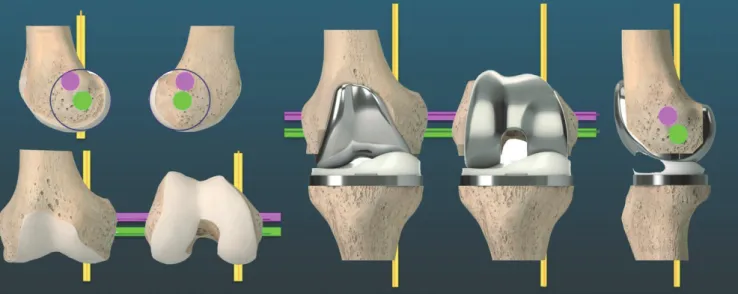
Kinematic studies of the natural knee have confirmed a single radius and single axis (primary femoral axis, cylindrical axis) for the posterior femoral condyles.26-28 In other words, the pri- mary femoral axis remains equidistant from the surface of both posterior femoral condyles.26,29 In order to perform kine- matic alignment, three kinematic axes must be applied de- pending on the predicted articular surface prior to arthritis. The most important kinematic axis passes through the center point of the best-fit circle of medial and lateral femoral condyles, and is termed the primary femoral axis (primary cylindrical axis).
This axis determines the position of femoral component about which the tibia flexes and extends. The basis for restoring nor- mal kinematics in TKA is alignment of the axis of femoral component with the primary femoral axis of the knee. There is a substantial difference between the primary femoral axis and transepicondylar axis equidistant from the surface of posterior femoral condylar surface. The primary femoral axis is more valgus and more internally rotated compared to the transepi- condylar axis.28 A secondary femoral axis is the transverse axis in the femur and is oriented parallel, proximal, and anterior to the primary femoral axis, and the patella flexes and extends around this axis. A third tibial axis is the longitudinal axis in the tibia, perpendicular to both the primary and secondary femo- ral axes, about which the tibia rotates on the femur internally and externally (Fig. 1).28-30
PREOPERATIVE PLANNING FOR MANUFACTURING A PSI
Reconstruction of 3D model
Using an 80-channel computed tomography (CT), 1-mm-thick CT images of the hip, knee, and ankle are obtained preopera- tively in the patient. A 3D medical image processing software is used to generate a 3D bone model of the lower extremity, including the femoral head, knee, and ankle. There are bene- fits and drawbacks of both CT and MRI scans for manufactur- ing PSI. CT scan is quick, easy to access, and provides better anatomical bone details, but is associated with increased expo- sure to radiation. MRI has the advantage of being able to mea- sure articular cartilage.31,32 Since the extent of cartilage damage in arthritic knee varies by region, cartilage thickness informa- tion is very important for secure PSI positioning. However, MRI also has some disadvantages, as it is associated with increased scanning time, claustrophobia, and higher cost, and cannot be used if there are metallic objects in the same or opposite limb.
There have been various results of the accuracy between CT- and MRI-based PSI. Pfitzner, et al.33 reported that MRI-based PSI was more accurate than CT-based PSI regarding the coro- nal mechanical limb axis, although differences were subtle and of questionable clinical relevance. Ensini, et al.34 compared MRI- based PSI TKAs with 25 CT-based PSI TKAs, and found no dif-
ference in the coronal alignment.
Preoperative determining of distal femoral flexion axis The femur is divided into three parts from the head to distal femoral joint line. From the upper margin of the distal one-third of the femur to metaphyseal flare, dots are marked (registered) with a pen forming a truncated cone. The distal flexion axis obtained from the best-fit line passes through the center of truncated cone (Fig. 2). Nedopil, et al.35 reported that patella in- stability occurred in 4% of patients undergoing kinematically aligned TKA with conventional instruments, which was asso- ciated with greater flexion of the femoral component (11° vs.
5°; p=0.0012). Therefore, minimizing the flexion of femoral com- ponent could reduce the risk of patellofemoral instability by promoting early engagement of patella in the trochlear during knee flexion. To avoid patella instability, we set the boundary below 11° for the difference of angle between distal femoral flexion axis and diaphyseal axis on sagittal plane. The measure- ment method for determining axes was described in the author’s previous article.36
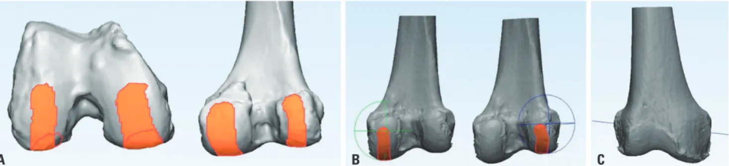
Preoperative determination of primary femoral axis The surfaces of distal femoral condyles were marked from the condylar sulcus to the posterior end of posterior condyles. The best-fit sphere was made from registered points, and putative positioning sphere’s center was equidistant from pre-arthritic articular surface. Primary femoral axis was made by connect- ing the centers of two spheres (Fig. 3). Howell, et al.37 reported there is no clinically relevant asymmetry between the radii of the best-fit circles of medial and lateral femoral condyles in var- us and valgus osteoarthritic knees in the Western population (≤0.2 mm).
Distal and posterior femoral bone cuts are equal in thickness
to the respective regions of femoral component in the kine- matically aligned TKA. Distal and posterior femoral bone cuts can be performed using reference to the articular surface or Fig. 1. The knee has three kinematic axes. Yellow line shows the longitudinal axis in the tibia that the tibia on the femur rotates about. In the femur, the green line shows transverse axes about which the tibia flexes and extends. Magenta line indicates the transverse axis of the femur that the patella flexes and extends about.
Fig. 2. From the upper margin, distal one-third to metaphyseal flare of the femur was registered with points by pen, which made a truncated cone. The distal femoral flexion axis was obtained as a line passing through the center of the truncated cone to the best fit.
primary femoral axis. Although the articular surface-based bone cut is commonly used in kinematically aligned TKA using conventional instruments, it is also used in PSI-guided kine- matic TKA. In the articular surface-based bone cut, posterior reference plane was made as a plane that included a tangential line connecting the most posterior points of medial and lateral femoral condyles. Distal reference plane was made parallel to the posterior plane, including a tangential line connecting the most distal points of medial and lateral femoral condyles. In the primary femoral axis-based bone cut, distal and femoral bone cutting was performed at the same distance from pri- mary femoral axis. Distal bone cutting was perpendicular to distal femoral flexion axis and parallel to primary femoral axis.
Niki, et al.7 compared the accuracy of the primary femoral axis based on bone cut and articular surface-based bone cut, and concluded that the primary femoral axis-based bone cut is preferable to the articular surface-based bone cut for reproduc- ing the primary femoral flexion-extension axis.
Preoperative determination of tibial alignment (varus- valgus and posterior slope)
A kinematic tibial cut is determined to be parallel to the artic-
ular surface of proximal tibia, defined by the plane of best fit to both plateaus (overall arthritic plateau).38 The registration process involves a surface centroid, excluding the surface of meniscus and tibial spines (Fig. 4). Nedopil, et al.39 reported that the tibial component failure after kinematically aligned TKA was 0.3%, and was caused by posterior subsidence or pos- terior edge wear and not varus subsidence. They also reported that tibial component failure group had a 5° greater posterior slope (mean 11.2°±3.1°, p=0.002) than the corresponding con- trol group (mean 6.0°±2.7°).
Preoperative determination of guide pin location Some PSI provides options for locating pins and bone cutting in one piece, and offers a complete single-use instrument set for TKA. This system is designed to improve logistics and in- strument management, offering substantial logistical and fi- nancial benefits in the surgery room and throughout the supply chain of hospitals. After locating the pins for bone resection, some PSIs use the pin positions for sitting separate convention- al cutting blocks (Fig. 5). PSI is designed to fit into the arthritic knee of each patient in only one specific position for accurate and secure fixation. Pin locations are determined according to Fig. 3. Preoperative determination of primary femoral axis. (A) Surfaces of each distal femoral condyle were marked from the distal portion in order to recess to posterior end of posterior condyles. (B) The best-fit sphere from each condyle was made from registered points, and putative positioning of sphere’s center was equidistant from pre-arthritic articular surface. (C) Cylindrical axis was made by connecting the centers of two spheres.
A B C
Fig. 4. Preoperative determination of tibial alignment. (A) The registration process involved a surface centroid excluding regional bone defect and tibi- al spines. (B) Tibial resection was planned by the plane of best fit to both plateaus (overall arthritic plateau).
A B
pre-planned kinematic alignment and bony resection thick- ness, using a computer software (Fig. 5).
SURGICAL TECHNIQUE
The anterior-posterior (A-P) offset, which is the distance be- tween distal medial condyle of the femur and anterior cortex of the tibia at 90° of the flexion of the knee, is measured before distal femoral resection (Fig. 6). PSI is seated and secured to its unique position on anterior surface of the femur. Since CT- based PSI does not take into account the thickness of the re- maining cartilage of the worn area, it is necessary to remove the remaining cartilage completely from the footprint of artic- ular surface contacted by PSI. After PSI is removed, distal cut is
made through a distal cutting guide, which is attached at two pin locations made of a PSI when using separate types. Next, the remaining femoral cuts are made by a chamfer guide, which is attached to two other pin locations made from a PSI on distal surface of the femur. For tibial cutting, PSI is seated and se- cured to its unique position on the articular surface of tibia. Af- ter PSI is removed, the tibia is cut with a cutting jig, which is at- tached at two pin locations made of a PSI when using separate types. The posterior cruciate ligament is preserved for more natural knee kinematics. A manual instrument technique is used to set the internal-external rotation of anterior-posterior axis of tibial component parallel to the major axis of an ellipse drawn on lateral tibial condyle.40,41 Balance of the knee and patella tracking is assessed qualitatively by manual and visual examinations. When an asymmetric laxity in coronal plane is
Fig. 6. Intra-operative measurement of anterior offset of the tibia from the femur. (A) Intra-operative images of a left knee with varus deformity in 90°
of flexion demonstrate the measurement of anterior offset of the tibia from the worn distal medial articular surface of the femur. (B) In order to restore the slope of the native proximal tibial joint line, the anterior-posterior slope and thickness of the tibial component are adjusted until the anterior tibia offset from the distal medial femoral condyle matches that of the knee at the time of exposure.
A B
Fig. 5. Preoperative determination of guide pin location. (A) Patient-specific instrument (PSI) was manufactured by considering the distance between pin hole and saw slot of the cutting block. (B) PSI was applied to the three-dimensional (3D) model of the patient’s tibia which was manufactured by 3D printer.
A B
Patient specific instrument
Tibia cutting level
Saw blade slot
Pin position Pin hole
Tibia cutting level
observed, the 2° varus or valgus re-cut guide is used to finely tune the tibial resection until the laxity is 1° or less like the na- tive knee. When the difference of an A-P offset is observed after inserting trial implants, posterior slope and thickness of the tib- ial component is adjusted until the A-P offset matches that of the knee at the time of exposure (Fig. 6). A step-wise algorithm is used for balancing the kinematically aligned TKA (Table 1).
SELECTION OF THE IMPLANT TO
PERFORM KINEMATICALLY ALIGNED TKA
Kinematically aligned TKA with an implant for mechanical alignment
Kinematic and mechanical alignment techniques have differ- ent philosophies, but most kinematically aligned TKAs use implants for mechanical alignment. The intended settings of the femoral component for mechanical alignment are 3° to 5°
external rotation relative to posterior condylar axis or tran- sepicondylar axis. Femoral components for mechanical align- ment are designed to maximize the proximal and lateral reach of the trochlea in order to promote early patella involvement, more normal patellar tracking, and even the distribution of contact stress on the patella.42-45 When performing kinemati- cally aligned TKA with an implant for mechanical alignment, femoral trochleae is substantially under-stuffed with reduc- tion in lateral reach, and it becomes more valgus than native trochlea.18,46 It is correlated with abnormal patellar tracking and an uneven distribution of contact stress on the patellar compo- nent.47 There is another concern regarding mid-flexion insta- bility in kinematically aligned TKA with implant for mechani- cal alignment. Incavo, et al.48 reported that kinematically aligned TKA demonstrated mid-flexion lateral joint space opening and late-flexion medial opening. Therefore, it is important to design an implant with the optimal shape for restoring natural knee kinematics that might improve patient-reported satisfac- tion and function.
Medial stabilized design implanted with kinematic alignment restores higher function, and offers better anterior stability than anterior cruciate ligament (ACL) and partial meniscal deficient designs
A promising strategy for kinematic alignment, which aims to restore high function and anterior stability and also reduce the risk of late tibial component failure from posterior rim wear of the insert, is to use a medial stabilized (MS) implant design with an insert consisting of a medial ball-and-socket and a lat- eral flat surface without a posterior rim (Fig. 7).49-52 In medial compartment, the insert should have a near 1:1 ball-and-sock- et conformity to promote A-P stability like the native knee. In lateral compartment, the insert should be flat without a poste- rior rim to enable internal-external (I-E) rotation of the tibia on the femur like the native knee.51 An insert without a posterior rim replicates the loss of constraint resulting from the lateral meniscus rolling off the posterior tibia when the knee is in deep flexion, and reduces the risk of instability from posterolateral rim wear.50
The benefits of the MS design were reported in a single sur- geon randomized trial which showed that the functional out- comes of patients who were treated with MS design (SAIPH) (n=53) were better than those treated with ACL and partial meniscal deficient designs (Vanguard CR) (n=50) implanted with kinematic alignment principles.50 Patients who were treat- ed with MS design had a 16-point higher self-reported Forgot- ten Joint Score than those treated with ACL and partial menis- cal deficient designs. The mean 80-point score of MS design is comparable to that of total hip arthroplasty.51 The greater ante- rior stability and more normal I-E rotation provided by MS de- sign explains its higher function compared to ACL and partial meniscal deficient designs.51
CONCLUSION
Kinematically aligned TKA is a new alignment technique for restoring natural tibial-femoral articular surface, alignment, Table 1. Step-Wise Algorithm for Balancing Kinematically Aligned Total Knee Arthroplasty
Tight in flexion &
extension
Tight in flexion well-balanced
in extension
Tight in extension well-balanced
in flexion
Well balanced in extension and loose
in flexion
Tight medial &
loose lateral in extension
Tight lateral and loose medial in extension Recut tibia and remove
1–2 mm more bone.
Increase posterior slope until exposure A-P offset is restored at 90°
of flexion.
Remove posterior osteophytes.
Strip posterior capsule.
Insert trial components
& gently manipulate knee into extension.
Add thicker insert and recheck knee extends fully.
When knee does not fully extend, check PCL tension.
When PCL is incompetent, consider PS implant or UC liner.
Remove medial osteophytes.
Reassess.
Recut tibia in 1°–2°
more varus.
Insert 2 mm thicker liner.
Remove lateral osteophytes.
Reassess.
Recut tibia in 1°–2°
more valgus.
Insert 2 mm thicker liner.
A-P, anterior-posterior; PCL, posterior cruciate ligament; PS, posterior-stabilized; UC, ultra-congruent.
Top row lists six malalignments, and bottom row lists the corresponding corrective actions. Notice that the corrections require recutting of the bone by fine-tun- ing the proximal-distal translation and the varus-valgus and flexion-extension (slope) rotations of the tibial resection, and not by recutting the femur.
and natural laxity of the knee. This alignment technique has shown promising implant survival at 10 years, as well as im- proved pain relief, function, and a more natural-feeling knee than treatment by mechanical alignment. In order to success- fully perform the kinematically aligned TKA, three kinematic axes must be correctly implemented. However, the implemen- tation of these axes using conventional instruments is com- plex and limited. PSI, designed to make surgery more simple and accurate, is a useful tool for implementing the kinemati- cally aligned TKA.
AUTHOR CONTRIBUTIONS
Conceptualization: Kwang-kyoun Kim. Data curation: Kwang-kyoun Kim. Formal analysis: Kwang-kyoun Kim. Investigation: Kwang-kyo- un Kim. Methodology: Kwang-kyoun Kim. Project administration:
Ye-yeon Won and Kwang-kyoun Kim. Resources: Kwang-kyoun Kim and Stephen M. Howell. Software: Kwang-kyoun Kim. Supervision:
Ye-yeon Won. Validation: Ye-yeon Won and Stephen M. Howell. Vi- sualization: Stephen M. Howell and Kwang-kyoun Kim. Writing—
original draft: Kwang-kyoun Kim. Writing—review & editing: Ye-yeon Won and Kwang-kyoun Kim. Approval of final manuscript: all authors.
ORCID iDs
Kwang-kyoun Kim https://orcid.org/0000-0002-6844-5431 Stephen M. Howell https://orcid.org/0000-0001-8184-0324 Ye-yeon Won https://orcid.org/0000-0002-1880-4336
REFERENCES
1. Cherian JJ, Kapadia BH, Banerjee S, Jauregui JJ, Issa K, Mont MA.
Mechanical, anatomical, and kinematic axis in TKA: concepts and practical applications. Curr Rev Musculoskelet Med 2014;7:89-95.
2. D’Lima DD, Hermida JC, Chen PC, Colwell CW Jr. Polyethylene wear and variations in knee kinematics. Clin Orthop Relat Res 2001;(392):124-30.
3. Sikorski JM. Alignment in total knee replacement. J Bone Joint Surg Br 2008;90:1121-7.
4. Morgan SS, Bonshahi A, Pradhan N, Gregory A, Gambhir A, Por- ter ML. The influence of postoperative coronal alignment on revi- sion surgery in total knee arthroplasty. Int Orthop 2008;32:639-42.
5. Baker PN, van der Meulen JH, Lewsey J, Gregg PJ. The role of pain and function in determining patient satisfaction after total knee replacement. Data from the National Joint Registry for England and Wales. J Bone Joint Surg Br 2007;89:893-900.
6. Bourne RB, Chesworth BM, Davis AM, Mahomed NN, Charron KD. Patient satisfaction after total knee arthroplasty: who is satis- fied and who is not? Clin Orthop Relat Res 2010;468:57-63.
7. Niki Y, Nagai K, Sassa T, Harato K, Suda Y. Comparison between cylindrical axis-reference and articular surface-reference femoral bone cut for total knee arthroplasty. Knee Surg Sports Traumatol Arthrosc 2017;25:3741-6.
8. Bonner TJ, Eardley WG, Patterson P, Gregg PJ. The effect of post- operative mechanical axis alignment on the survival of primary total knee replacements after a follow-up of 15 years. J Bone Joint Surg Br 2011;93-B:1217-22.
9. Luyckx T, Vanhoorebeeck F, Bellemans J. Should we aim at under- correction when doing a total knee arthroplasty? Knee Surg Sports Traumatol Arthrosc 2015;23:1706-12.
10. Parratte S, Pagnano MW, Trousdale RT, Berry DJ. Effect of postop- erative mechanical axis alignment on the fifteen-year survival of modern, cemented total knee replacements. J Bone Joint Surg Fig. 7. This composite shows the tibiofemoral relationship of medial and lateral compartments of the native knee in full extension and full extension, in which medial femoral condyle hardly moves (orange square) and lateral femoral condyle rolls posterior in full flexion (orange rectangle). The design of cruciate retaining (CR) insert, consisting of a medial ball-and-socket and a lateral flat surface without a posterior rim, is a promising strategy for promoting A-P stability and reducing the risk of late tibial component failure from posterior rim wear of the insert.
CR-medial socket
CR-lateral flat no rim Medial compartment
Lateral compartment
Full extension Full flexion
Am 2010;92:2143-9.
11. Vanlommel L, Vanlommel J, Claes S, Bellemans J. Slight under- correction following total knee arthroplasty results in superior clinical outcomes in varus knees. Knee Surg Sports Traumatol Ar- throsc 2013;21:2325-30.
12. Lee SS, Lee H, Lee DH, Moon YW. Slight under-correction follow- ing total knee arthroplasty for a valgus knee results in similar clin- ical outcomes. Arch Orthop Trauma Surg 2018;138:1011-9.
13. Magnussen RA, Weppe F, Demey G, Servien E, Lustig S. Residual varus alignment does not compromise results of TKAs in patients with preoperative varus. Clin Orthop Relat Res 2011;469:3443-50.
14. Shelton TJ, Nedopil AJ, Howell SM, Hull ML. Do varus or valgus outliers have higher forces in the medial or lateral compartments than those which are in-range after a kinematically aligned total knee arthroplasty? Limb and joint line alignment after kinematically aligned total knee arthroplasty. Bone Joint J 2017;99-B:1319-28.
15. Miller EJ, Pagnano MW, Kaufman KR. Tibiofemoral alignment in posterior stabilized total knee arthroplasty: static alignment does not predict dynamic tibial plateau loading. J Orthop Res 2014;32:
1068-74.
16. Calliess T, Bauer K, Stukenborg-Colsman C, Windhagen H, Budde S, Ettinger M. PSI kinematic versus non-PSI mechanical alignment in total knee arthroplasty: a prospective, randomized study. Knee Surg Sports Traumatol Arthrosc 2017;25:1743-8.
17. Waterson HB, Clement ND, Eyres KS, Mandalia VI, Toms AD. The early outcome of kinematic versus mechanical alignment in total knee arthroplasty: a prospective randomized control trial. Bone Joint J 2016;98-B:1360-8.
18. Dossett HG, Estrada NA, Swartz GJ, LeFevre GW, Kwasman BG. A randomised controlled trial of kinematically and mechanically aligned total knee replacements: two-year clinical results. Bone Joint J 2014;96-B:907-13.
19. Nam D, Nunley RM, Barrack RL. Patient dissatisfaction following total knee replacement: a growing concern? Bone Joint J 2014;96- B(11 Supple A):96-100.
20. Young SW, Walker ML, Bayan A, Briant-Evans T, Pavlou P, Far- rington B. The Chitranjan S. Ranawat Award: No difference in 2-year functional outcomes using kinematic versus mechanical alignment in TKA: a randomized controlled clinical trial. Clin Or- thop Relat Res 2017;475:9-20.
21. Howell SM, Howell SJ, Kuznik KT, Cohen J, Hull ML. Does a kine- matically aligned total knee arthroplasty restore function without failure regardless of alignment category? Clin Orthop Relat Res 2013;471:1000-7.
22. Howell SM, Papadopoulos S, Kuznik K, Ghaly LR, Hull ML. Does varus alignment adversely affect implant survival and function six years after kinematically aligned total knee arthroplasty? Int Orthop 2015;39:2117-24.
23. Howell SM, Shelton TJ, Hull ML. Implant survival and function ten years after kinematically aligned total knee arthroplasty. J Ar- throplasty 2018;33:3678-84.
24. Howell SM, Kuznik K, Hull ML, Siston RA. Results of an initial ex- perience with custom-fit positioning total knee arthroplasty in a series of 48 patients. Orthopedics 2008;31:857-63.
25. Klatt BA, Goyal N, Austin MS, Hozack WJ. Custom-fit total knee arthroplasty (OtisKnee) results in malalignment. J Arthroplasty 2008;23:26-9.
26. Weber W, Weber E. Mechanics of the human walking apparatus.
Maquet P, Furlong R, translators. Berlin: Springer Verlag; 1992. Sec- tion 4: On the knee; p.75.
27. Eckhoff DG, Bach JM, Spitzer VM, Reinig KD, Bagur MM, Baldini TH, et al. Three-dimensional mechanics, kinematics, and mor- phology of the knee viewed in virtual reality. J Bone Joint Surg Am
2005;87 Suppl 2:71-80.
28. Eckhoff D, Hogan C, DiMatteo L, Robinson M, Bach J. Difference between the epicondylar and cylindrical axis of the knee. Clin Or- thop Relat Res 2007;461:238-44.
29. Hollister AM, Jatana S, Singh AK, Sullivan WW, Lupichuk AG. The axes of rotation of the knee. Clin Orthop Relat Res 1993;(290):259- 68.
30. Iranpour F, Merican AM, Baena FR, Cobb JP, Amis AA. Patello- femoral joint kinematics: the circular path of the patella around the trochlear axis. J Orthop Res 2010;28:589-94.
31. Griffin FM, Math K, Scuderi GR, Insall JN, Poilvache PL. Anatomy of the epicondyles of the distal femur: MRI analysis of normal knees. J Arthroplasty 2000;15:354-9.
32. Chan WP, Lang P, Stevens MP, Sack K, Majumdar S, Stoller DW, et al. Osteoarthritis of the knee: comparison of radiography, CT, and MR imaging to assess extent and severity. AJR Am J Roentgenol 1991;157:799-806.
33. Pfitzner T, Röhner E, Preininger B, Perka C, Matziolis G. Femur po- sitioning in navigated total knee arthroplasty. Orthopedics 2012;
35(10 Suppl):45-9.
34. Ensini A, Timoncini A, Cenni F, Belvedere C, Fusai F, Leardini A, et al. Intra- and post-operative accuracy assessments of two dif- ferent patient-specific instrumentation systems for total knee re- placement. Knee Surg Sports Traumatol Arthrosc 2014;22:621-9.
35. Nedopil AJ, Howell SM, Hull ML. What clinical characteristics and radiographic parameters are associated with patellofemoral instability after kinematically aligned total knee arthroplasty? Int Orthop 2017;41:283-91.
36. Kim K, Kim J, Lee D, Lim S, Eom J. The accuracy of alignment de- termined by patient-specific instrumentation system in total knee arthroplasty. Knee Surg Relat Res 2019;31:19-24.
37. Howell SM, Howell SJ, Hull ML. Assessment of the radii of the me- dial and lateral femoral condyles in varus and valgus knees with osteoarthritis. J Bone Joint Surg Am 2010;92:98-104.
38. Johnson JM, Mahfouz MR, Midilliog˘lu MR, Nedopil AJ, Howell SM. Three-dimensional analysis of the tibial resection plane rela- tive to the arthritic tibial plateau in total knee arthroplasty. J Exp Orthop 2017;4:27.
39. Nedopil AJ, Howell SM, Hull ML. What mechanisms are associat- ed with tibial component failure after kinematically-aligned total knee arthroplasty? Int Orthop 2017;41:1561-9.
40. Ikeuchi M, Yamanaka N, Okanoue Y, Ueta E, Tani T. Determining the rotational alignment of the tibial component at total knee re- placement: a comparison of two techniques. J Bone Joint Surg Br 2007;89:45-9.
41. Coughlin KM, Incavo SJ, Churchill DL, Beynnon BD. Tibial axis and patellar position relative to the femoral epicondylar axis dur- ing squatting. J Arthroplasty 2003;18:1048-55.
42. Akagi M, Matsusue Y, Mata T, Asada Y, Horiguchi M, Iida H, et al.
Effect of rotational alignment on patellar tracking in total knee ar- throplasty. Clin Orthop Relat Res 1999;(366):155-63.
43. Rhoads DD, Noble PC, Reuben JD, Mahoney OM, Tullos HS. The effect of femoral component position on patellar tracking after total knee arthroplasty. Clin Orthop Relat Res 1990;(260):43-51.
44. Steinbrück A, Schröder C, Woiczinski M, Fottner A, Müller PE, Jansson V. The effect of trochlea tilting on patellofemoral contact patterns after total knee arthroplasty: an in vitro study. Arch Orthop Trauma Surg 2014;134:867-72.
45. Rivière C, Iranpour F, Harris S, Auvinet E, Aframian A, Parratte S, et al. Differences in trochlear parameters between native and pros- thetic kinematically or mechanically aligned knees. Orthop Trau- matol Surg Res 2018;104:165-70.
46. Ishikawa M, Kuriyama S, Ito H, Furu M, Nakamura S, Matsuda S.
Kinematic alignment produces near-normal knee motion but in- creases contact stress after total knee arthroplasty: a case study on a single implant design. Knee 2015;22:206-12.
47. Anouchi YS, Whiteside LA, Kaiser AD, Milliano MT. The effects of axial rotational alignment of the femoral component on knee sta- bility and patellar tracking in total knee arthroplasty demonstrated on autopsy specimens. Clin Orthop Relat Res 1993;(287):170-7.
48. Incavo SJ, Schmid S, Sreenivas K, Ismaily S, Noble PC. Total knee arthroplasty using anatomic alignment can produce mid-flexion laxity. Clin Biomech (Bristol, Avon) 2013;28:429-35.
49. Freeman MA, Pinskerova V. The movement of the normal tibio- femoral joint. J Biomech 2005;38:197-208.
50. French SR, Munir S, Brighton R. A single surgeon series compar-
ing the outcomes of a cruciate retaining and medially stabilized total knee arthroplasty using kinematic alignment principles. J Ar- throplasty 2020;35:422-8.
51. Schütz P, Taylor WR, Postolka B, Fucentese SF, Koch PP, Freeman MA, et al. Kinematic evaluation of the GMK sphere implant dur- ing gait activities: a dynamic video fluoroscopy study. J Orthop Res 2019;37:2337-47.
52. Nicolet-Petersen S, Saiz A, Shelton T, Howell SM, Hull ML. Small differences in tibial contact locations following kinematically aligned TKA from the native contralateral knee. Knee Surg Sports Traumatol Arthrosc 2019 Aug 13 [Epub]. Available at: https://doi.
org/10.1007/s00167-019-05658-1.