펄스파워 전류 측정용 센서 개발 및 특성 평가
Development of Current Sensor for Pulsed Power and its
Characteristics Evaluation
한 상 보
* ★
Sang-Bo Han* ★
Abstract
This paper shows the development of current sensor for the measurement of hundreds of nanoseconds large current in pulsed power and its characteristics evaluation. The developed current sensor was designed for measuring induced voltage from magnetic flux under the operation of pulsed power. Output characteristics of developed current sensor was good consistent with commercial one, and the realistic current of fast pulsed power was detected easily with the calibration curve using output voltage of developed sensor. Therefore, the developed current sensor is possible to apply the realistic system.
요 약
본 논문은 펄스파워 동작시의 수백 ns의 대전류를 측정하기 위한 전류 센서의 개발과 특성평가 결과에 대하여 논하였다.
개발된 전류 센서는 펄스 파워 동작시 전류에 의해 발생되는 자속으로부터 유기기전력을 측정하도록 특별히 설계하였다. 개 발 된 전류 센서의 출력 특성은 상업용 센서의 출력 특성과 매우 일치하였으며, 개발 된 센서의 출력 전압 검량선을 이용하 여 빠른 펄스 파워의 실제 전류를 쉽게 검출 할 수 있음을 보였다. 따라서, 본 연구에서 개발 된 전류 센서는 실제적인 펄스 파워 시스템에 적용할 수 있음을 확인하였다.
Key words : Current, Induced Voltage, Magnetic Flux, Pulsed Power, Sensor
* Dept. of Electrical Engineering, Kyungnam University
※ Acknowledgment
E-mail:[email protected], Tel:+82-55-249-2635
This work was supported by Kyungnam University Foundation Grant, 20170183 Manuscript received Mar. 12, 2019; revised Mar. 18, 2019; accepted Mar. 18, 2019.
This is an Open-Access article distributed under the terms of the Creative Commons Attribution Non-Commercial License (http://creativecommons.org/licenses/by-nc/3.0) which permits unrestricted non-commercial use, distribution, and reproduction in any medium, provided the original work is properly cited.
Ⅰ. 서론
전기에너지를 커패시터 또는 인덕터와 같은 에너 지 저장 소자에 충전하고, 충전된 에너지를 스위칭 을 통해 매우 짧은시간에 공급하는 펄스파워 기술 은 레이져 발진, x선 및 중성자 빔 발생, 전력기기 의 대전류 시험전원, 순간 전자력 발생, 지구탐사, 기계가공, 레일 건(rail gun), 식품처리, 의료 응용,
수처리, 오존 발생 등 다양한 분야에 응용되고 있다.
특히, 펄스파워 기술은 수 백 나노초(nanoseconds) 이하인 매우 짧은 시간동안에 대전류를 흘려 플라 즈마 핀치(pinch)를 생성시키는 플라즈마 포커스 (plasma focus) 기술에 의하여 x선, 중성자 빔, 이온 빔, EUV(Extreme Ultraviolet)와 같은 전자기파를 발생시키는 연구가 활발히 진행되고 있다[1]-[6].
또한, 부하 또는 선로의 임피던스를 조정하여 펄
230
Material: Cu, Unit: mm
Bolting hole Part 1: Cover
Part 2: Main body Sensing hole
(a) 전류센서 설계도(조립 전)
Conductor
A A
to OSC. Current
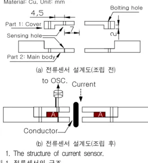
(b) 전류센서 설계도(조립 후) Fig. 1. The structure of current sensor.
그림 1. 전류센서의 구조
스를 압축시키고, 병렬 중첩시킨 케이블을 이용하 여 펄스를 발생시키는 Blumlein 펄스파워 발생 전 원장치에 관한 연구[7]-[8], 펄스파워를 이용한 레 이져 발진 연구[9] 등 다양한 응용연구가 추진되고 있다. 이러한 펄스파워 기술은 고전압 충전 및 방 전 제어기술, 펄스 성형 기술, 스위칭소자 제어기 술, 측정 및 분석기술 등이 종합적으로 필요하다.
특히, 펄스파워 발생 순간의 수백 kA까지의 대전 류 측정은 선로에 존재하는 인덕턴스 및 커패시턴 스(stray inductance and capacitance), 그리고 타 회로와의 간섭을 최소화시켜야 한다. 이를 위하여 펄스파워 발생 위치에 가능한 가까운 곳에 전류 또 는 전압센서를 부착시켜 펄스파워의 특성을 파악 하고 있다.
본 연구에서는 펄스파워 동작시 발생되는 대전류 를 효율적으로 측정하기 위하여 센서를 자체적으 로 설계 및 제작하고, 제작된 센서의 출력특성 측 정 및 분석결과에 대하여 논하였다.
Ⅱ. 본론
2.1 전류센서 설계 및 제작
그림 1 및 사진 1은 본 연구에서 자체 설계 및 제 작한 전류센서를 나타낸 것으로서, 그림 1(b) 설계 도에서 중앙 도체(conductor) 부분에 흐르는 전류 에 의하여 공간 A에 발생되는 자속을 동축케이블 (50Ω)에 의하여 식(1)과 같이 유도기전력으로 측 정되도록 설계하였다. 이때의 유도기전력은 자속이
통과되는 단면적이 넓을수록 더 높은 전압이 유기 되며, 식(2)에서와 같이 적분하여 전류로 변환할 수 있다.
유기기전력을 측정하기 위한 동축케이블은 내부 도체 직경 0.3[mm]이며, 내부 도체와 외부 금속관 사이에는 테플론으로 절연처리되어 있는 특수 케 이블을 사용하였다. 본 연구에서 설계한 전류센서 의 제원을 표 1에 나타내었다.
(1)
(2)(
)여기서,
, ,
×
, , r는 자속이 통과하는 평균 반 지름
Table 1. Specification of current sensor for this work.
표 1. 본 연구에서 설계한 전류센서의 제원
n [turns] s [mm
2] r [mm]
1 9 9.25
Pic. 1. Pictures for manufactured current sensor.
사진 1. 제작된 전류센서의 사진
2.2 전류센서의 출력특성 분석
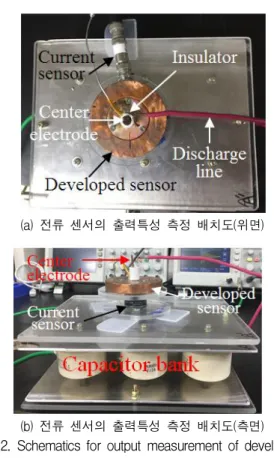
그림 2와 그림 3은 본 연구에서 설계한 전류센서의 출력특성을 측정하기 위한 외관사진 및 실제의 회 로도를 각각 나타낸 것으로서, 본 연구에서 설계한 전류센서(CT1)와 상업용 전류센서(Pearson Current Monitor, 2878, CT2)를 동일 위치에 배치하여 동시 측정하도록 구성하였다.
(a) 전류센서의 출력 전압파형
(b) 센서 출력전압의 전류변환파형
(c) 센서의 출력특성 비교
Fig. 4. Output voltage and transformed current waveforms of developed current sensor.
그림 4. 개발한 전류센서의 출력전압파형 및 전류변환파형 (a) 전류 센서의 출력특성 측정 배치도(위면)
(b) 전류 센서의 출력특성 측정 배치도(측면) Fig. 2. Schematics for output measurement of developed
current sensor.
그림 2. 개발한 전류센서의 출력특성 측정 구성도
11.7 nF (parallel 6ea)
C
. .
CT 1
H.V. D C
CT 2
charge discharge
discharge gap S
1(switch) S
2(switch)
+
ㅡ
Fig. 3. Measurement circuit for output characteristics of the developed current sensor.
그림 3. 개발한 전류센서의 출력특성 측정회로
출력특성 측정은 그림 3에서와 같이 DC 고전압 전원(SHV 120, 25kV, Convert Tech.)을 이용하여 S1 스위치를 투입하여 병렬연결된 6개의 콘덴서로 구성된 콘덴서 뱅크(MURATA 006, 30kV D.C)에 일정한 전압까지 충전하고, 충전이 완료되면 S1 스 위치를 개방시키고, S2 스위치 투입시 발생되는 방 전전류를 두 전류센서에 의해 측정하도록 구성하 였다. 단, 이때 상업용 전류센서(CT2)는 오실로스 코프 최대범위 내에서 측정하기 위하여 감쇄기 (20dB, 50Ω)를 연결하여 측정하였다.
그림 4는 자체 제작한 전류센서의 유기기전력에 해당되는 출력 전압파형과 전류로 변환된 파형 및 두 센서의 출력특성 비교를 나타내었다. 그림 4(a) 에서 상업용 전류센서의 상승시간이 100ns에 해당 되며, 자체제작 전류센서에 유기전압이 렌츠의 법 칙에 의해 반대부호 방향으로 발생됨을 알 수 있으 며, CT2가 최대인 곳에서 CT1은 0[V]이며, CT2 0[V]에서 CT1이 최대의 값을 나타내었다. 이것은 방전전류에 의한 자속이 유기기전력으로 적절하게 측정됨을 의미한다. 그림 4(b)는 식 (2)를 적용하여 유기기전력을 전류로 변환한 결과를 보인 것으로 서, 렌츠의 법칙에 따라서 부호가 반전되었다. 그림 4(c)는 자체 개발한 전류센서와 상업용 센서의 출
력특성을 비교한 것으로서, 자체 제작한 전류센서 가 상업용 센서에 비해서 초기에 더욱 민감하고 빠 르게 상승하는 경향이 있지만, 거의 유사한 특성을 보이고 있음을 알 수 있다.
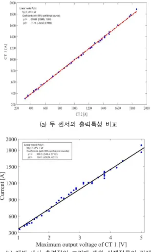
그림 5(a)는 자체 개발한 전류센서와 상업용 전 류센서와의 출력특성 상관관계를 나타낸 것으로서, 기울기 0.9988로서 개발 전류센서가 상업용 전류센 서와 거의 동일한 비율로 측정됨을 알 수 있다. 또 한, 그림 5(b)는 자체 개발한 전류센서의 출력전압 의 최대치와 실제 흐르는 전류와의 상관관계를 나 타낸 검량선으로서, 본 연구에서 자체 개발한 전류 센서의 출력(유기기전력)을 이용하여 펄스파워 동 작시의 전류를 쉽게 측정하는 것이 가능함을 알 수 있다.
(a) 두 센서의 출력특성 비교
(b) 개발 센서 출력전압 크기에 대한 실제전류의 관계 Fig. 5. Comparison of output characteristics of two current
sensors and correlation between output voltage of developed sensor and realistic current.
그림 5. 두 센서의 출력특성비교 및 개발센서 출력 최대 전압 크기에 따른 실제전류와의 관계
Ⅲ. 결론
본 논문은 펄스파워 출력 순간의 대전류를 측정 하기 위한 전류센서 개발에 관한 연구로서, 개발된 센서의 출력특성 분석을 통하여 아래의 주요한 결 과를 도출하였다.
1) 개발한 전류센서와 상업용 전류센서와의 출력 특성이 거의 동일한 비율로 측정됨을 확인하였으 며, 개발한 전류센서가 펄스파워 전류측정에 적용 가능함을 확인하였음.
2) 개발한 전류센서의 출력전압의 최대치와 실제 흐르는 전류와의 상관관계를 나타낸 검량선을 통 하여 출력 전압을 이용해 펄스파워 전류를 쉽게 측 정할 수 있음을 보였음.
References
[1] Hansjoachim Bluhm, “Pulsed Power Systems - Principles and Applications,” Springer, 135-155, 2006.
[2] M. G. Haines, S. V. Lebedev, J. P. Chittenden, F. N. Beg, S. N. Bland, and A. E. Dangor, “The Past, Present, and Future of Z Pinches,” Physics
of Plasma 7, 1672, 2000.
[3] Hidenori Akiyama, Takashi Sakugawa, Takashi Sakugawa, T. Namihira, and T. Namihira, “industrial applications of pulsed power technology,” IEEE
Trans. on Dielec. and Electrical Insul. 14(5),
1051-106, 2007. DOI: 10.1109/TDEI.2007.4339465 [4] Moon, Minwug, “The coaxial focused plasma for EUV (Extreme Ultraviolet) light source design and diagnostics,” doctor dissertation, KwangWoon Univ., 2007.[5] A. BERNARD et. al., “The Dense Plasma Focus - A High Intensity Neutron Source,” Nuclear
Ins. and Methods, Vol. 145, 191-218, 1977.
DOI: 10.1016/0029-554X(77)90569-9
[6] J. W. Mather, “Formation of High-Density Deuterium Plasma Focus,” Physics of Flu, Vol. 8, No. 2, 1965.
[7] Mohamed O. Twati, A. Ben Otman, “Distributed parameter analysis of a blumlein-line N2 laser,”
Optics Commu., Vol. 99, Issues 5-6, 405-412,
1993. DOI: 10.1016/0030-4018(93)90350-E[8] Li Chen, Bailiang Pan, Ya Juan Wang, Krassimir A. Temelkov, Nikolay K. Vuchkov,
“He–SrCl2 vapor laser excited by Blumlein discharge circuit,” Optics Commu., Vol. 282, Issue 19, 3953-3956, 2009.
DOI: 10.1016/j.optcom.2009.06.059
[9] F. Castillo, M. Milanese, R. Moroso, and J.
Poujo, “Evidence of thermal and non-thermal mechanisms coexisting in dense plasma focus D-D nuclear reactions,” J. Phys. D: Appl. Phys.
33, 141, 2000. DOI: 10.1088/0022-3727/33/2/308
BIOGRAPHY