http://dx.doi.org/10.7839/ksfc.2017.14.3.018
The Numerical Modeling and Sliding Mode Control of A New Submersible Fish Cage
Hyunsu Lee
1, Sung Jae Won
2and Kyoung Kwan Ahn
1*
Received: 16 May. 2017, Revised: 26 Jun. 2017, Accepted: 24 Jul. 2017 Key Words:Submersible Fish Cage, Bottom-opened Structure, Sliding Mode Control
Abstract: The purpose of this paper is to develop a new submersible fish cage operated by a pneumatic system for offshore aquaculture. Although some researchers have investigated modeling and control of fish cages, such cages consist of variable ballast tanks that with closed cylinders and thus present a maintenance issue. In solving the issue the new submersible fish cage investigated consists of bottom-opening cylinders. Accordingly, we designed a mathematical model of the concept and applied Sliding Mode Control for nonlinear angle control. Some experiments conducted under assumed conditions indicate that the angle of the system converges to zero under all conditions and the control has the stability to balance the fish cage.
* Corresponding author: [email protected]
1 School of Mechanical and Automotive Engineering, University of Ulsan, Ulsan 44610, Republic of Korea
2 R&D center, BMInternational, Busan 49489, Republic of Korea
Copyright Ⓒ 2017, KSFC
This is an Open-Access article distributed under the terms of the Creative Commons Attribution Non-Commercial License(http://
creativecommons.org/licenses/by-nc/3.0) which permits unrestricted non-commercial use, distribution, and reproduction in any medium, provided the original work is properly cited.
1. Introduction
As population increased, the need of essential nutrients abundantly contained in fish and seaweed is also being increased steeply. Coastal region to crop the seafood is, however, restricted by many systems already installed including fish cages, vacation spots and power plants. These limited conditions force aquacultural systems to be displaced from coastal to offshore region.
As many offshore aquacultural systems are operated by farmers on ferry and placed in water for a long time, pneumatic systems are suitable for reasons related to their good power/weight ratio, easy maintenance and assembly operations, clean operating conditions and low cost1). However, compressibility of air and highly nonlinear flow through pneumatic system components
make pneumatic devices have bad controllability and occupy small space in industrial applications.
Nevertheless, submersible fish cage operated by pneumatic system had been studied by many researchers as the one of offshore aquacultural systems. Recent researches mostly have, however, been focused on modeling of net cage structure and feeding2-5).
Although some researchers investigated modeling and control of fish cage system, they overlooked physical properties of air including compressibility and nonlinearity. The fish cage was, moreover, made up of variable ballast tanks that consist of closed cylinders6-10). As fish cage in offshore is placed in water for a long time, it is unsuitable to use hydraulic valves that sea water pass through in terms of maintenance.
For solving the problem above mentioned new fish cage is made up of bottom-opened cylinders. The characteristics of air makes, however, opened system become more complex to control.
Therefore, we design analytically mathematical model of the newest submersible fish cage system has open cylinders in detail, and then utilize the Sliding Mode Control (SMC) theory for nonlinear angle control implementation, considering its robustness and high performance characteristics even for highly nonlinear
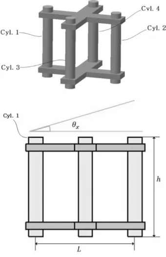
Fig. 1 Submersible fish cage system systems11). The validity of the modeling and control
logic is finally verified by experiments based on real situations.
2. System Description and Modeling
The current section provides brief explanation of how the fish cage works and how numerical modeling is derived. Details of system structure and derivation of basic equations are omitted for the sake of brevity.
2.1 System Description
The submersible fish cage system consists of float, mooring system, anchor system and fish cage having four open cylinders as shown in Fig. 1. The fish cage is usually located in water and stretched by mooring system in order to preserve the fish stock from the destructive environmental events8). As the need to feed fish, pneumatic system equipped in ferry can raise the fish cage.
In the ordinary way, due to the absence of power source it is efficient to use mooring system, float and auxiliary cylinders to maintain descended position of fish cage. Inserting little air into open cylinders, the cage can be ascended. In this process, inequality of air volume put in each cylinder and wave affect an angle of the cage.
The angle of bottom-opened cage makes the system unstable and must be controlled. What we have to consider is, therefore, only angle control of fish cage in the process of ascending and descending.
We will treat the control problem in section 3.
2.2 Mathematical Modeling
The differential equation for the rates of change of the pressure in each cylinder is1)
(1)
where is the absolute pressure of each cylinder, k is the specific heat ratio, is the air volume of each cylinder, R is the gas constant, is the inlet temperature of the air going into the cylinder, is the temperature of the air in each cylinder, A is the area of cylinder, is the time derivative of the inside water level of cylinder, is the input air mass flow to cylinder and is the output air mass flow from cylinder. The standard equation describing mass flow of air is12)
(2)
where is the dimensionless, discharge coefficient of the orifice, is the orifice area, is the upstream pressure, is the upstream temperature, is the downstream pressure and
are constant for a given fluid13). For air we have
=0.040418, =0.156174 and =0.52
Now we present the dynamic equation of the experimental model of fish cage shown in Fig. 2. The dynamic equation describing vertical motion of cage is
(3)
where is the depth of cage from sea level, M is the mass of cage, is the density of water, g is the gravitational acceleration, is the auxiliary force by other components, h is the height of cylinder, is the pressure gradient by depth of water, is the dimensionless drag coefficient and is the frontal area, the projected area seen by a person looking toward the object from a direction parallel to the
Fig. 2 The fish cage model
upstream velocity, of total system. The fourth term of (3) represents the constant force arising from pressure increment depending on depth and the fifth term of (3) is the drag, reaction force for speed of system and the approximate value of is determined by means of a simplified analysis or an appropriate experiment 14).
As cylinders opened, the equation about movement of water level inside cylinder is expressed as
(4)
where is the inside surface of water of each cylinder, is the weight of water filled in cylinder, L is the horizontal length of cage, is the angle of system, is the or meaning axis and is the atmospheric pressure that added in equation to match absolute pressure. The terms in brace of (4) represent the water pressure acting on bottom area of each cylinder.
Finally, using moment equation we can describe rotation of cage as follows
(5)
(6)
where I is the moment of inertia of system and is obtained by experiment for covering the reaction force about rotational motion. It makes the calculation of control law concise.
3. Controller Design
As explained previously, what we only consider is angle control of cage in the process of ascending and descending. Since the use of level sensor is constrained from maintenance problem, we replace the level of water inside cylinders with mass using ideal gas equation in control logic. Thus we utilize SMC, a kind of robust control. The detailed derivation of following equations is in the Appendix for the sake of brevity.
Hoping zero angle of cage ( ) sliding
surfaces are defined as
(7)
(8)
where are constants decided by the trial and error method.
Substituting Eq. (5), (6) and ideal gas equation and using few assumptions, differentiation of Eq. (7) and (8) can be written as follows
(9)
(10)
Setting Eq. (9) and (10) equal to zero and solving for u , we can take equivalent control .
For satisfying the sliding condition, , the control law of fish cage is defined as
(11)
(12)
where K is the controller gain defined as a function of the state variables, φ is the thickness of a thin boundary layer introduced to avoid chattering11) and sign and sat are functions expressed as follows
The controller gain K can be chosen function of angle as follows
where and are the constants obtained by the trial and error method15-17).
4. Simulation and Experimental Verification
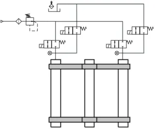
The validity of the numerical model and control logic is verified by experiment in this section. The simulation of modeling is carried out using Simulink in MATLAB and Runge-Kutta method. We set fixed step size ms and neglected time delay. The pneumatic circuit of total system is briefly depicted in Fig. 3 and Fig. 4 represents the real test rig. Discharge coefficient of each 2-way valve (TV2W03) was found by experiment,
. The control logic is conducted by online processing of transmitted data from pressure sensor (PSE543) and angle sensor (MSENS) every sampling time.
Fig. 3 The experimental setup: pneumatic circuit
Fig. 4 The experimental setup: test rig
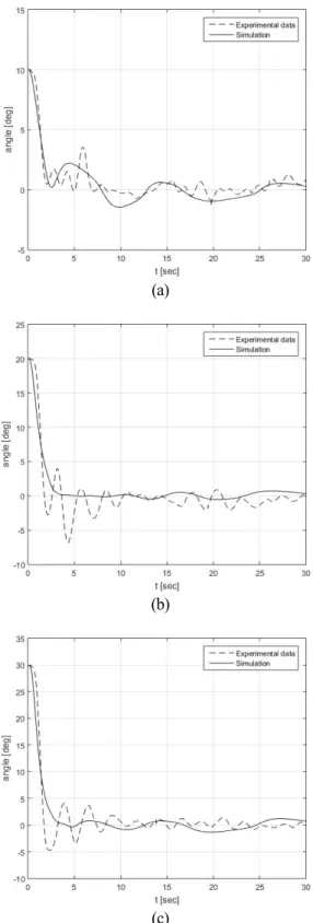
Fig. 5 depicts comparison of numerical simulation and experiment. Initial point of inside water level of each cylinder is identical (xi m) to describe the circumstance affected by wave and each graph is classified by initial angle of system.
(a)
(b)
(c)
Fig. 5 The test results, initial degree (a) °, (b) °, (c) °
Fig. 6 depicts another comparison of numerical simulation and experiment. Initial point of inside water level of each cylinder is different (x m, x m or x m respectively) to describe the circumstance affected by inequality of magnitude of put air.
(a)
(b)
Fig. 6 The test results, water level difference (a) x m , (b) x m
Quite big difference between simulation and experiment is observed. Even if LPF eliminated noise of pressure sensor, the differential of signal made noise amplified and affected magnitude of equivalent control.
The differential of angle signal influenced, furthermore, sliding surface and made control of system change frequently. These observational errors aggravated accuracy of the level of water inside cylinders substituted with mass in control logic.
5. Conclusion.
In this article numerical modeling of the newest submersible fish cage consists of open cylinders was carried out in detail by considering nonlinearity of air and the SMC was conducted to keep angle of fish cage stable. From a conservational point of view the inside water level of cylinders was substituted in control logic, but this effected a degradation of modeling accuracy.
Furthermore, the differential of sensor signal aggravated control logic. Nevertheless, we observed that the angle of system converges to zero and the control logic of system is stable under all assumed circumstances.
Acknowledgement
This research was a part of the project titled 'R&D center for underwater construction robotics', funded by the Ministry of Oceans and Fisheries(MOF) and Korea Institute of Marine Science&Technology Promotion (KIMST), Korea.(PJT200539)
Appendix
In this section we derive the control method expressed as Eq. (11). The procedure of derivation of Eq. (12) is omitted owing to similarity.
Differentiation of Eq. (7) is described as
. (A.1)
Substituting Eq. (5) in Eq. (A.1), the differential of sliding surface is represented as
(A.2)
Assuming temperature of inlet and outlet is same and using simple notation, Eq. (1) can be expressed as
(A.3)
and the ideal gas equation is
(A.4)
By substituting Eq. (A.3), (A.4) in Eq. (A.2) we can take Eq. (9) and setting Eq. (9) equal to zero and solving for u, is defined as
(A.5)
From Eq. (A.5) the control method Eq. (11) always satisfy sliding condition, .
References
1) Blackburn, J.F., Reethof, G., Shearer, J., 1960.
Fluid Power Control. MIT Press.
2) Fullerton, B., Swift, M.R., Boduch, S., Eroshkin, O., Rice, G., 2004. Design and analysis of an automated feed-buoy for submerged cages.
Aquacult. Eng. 32, 95-111.
3) Huang, C., Tang, H., Liu, J., 2006. Dynamical analysis of net cage structures for marine aquaculture: Numerical simulation and model testing. Aquacult. Eng. 35, 258-270.
4) Kim, T., Hur, J., Yang, K., 2010. Submerging performances of automatic submersible buoy operated by air control. Journal of the Korean Society of Marine Engineering 34, 743-749.
5) Kim, T.H., Yang, K.U., Hwang, K.S., Jang, D.J., Hur, J.G., 2011. Automatic submerging and surfacing performances of model submersible fish cage system operated by air control. Aquacult. Eng.
45, 74-86.
6) Lee, P.G., 2000. Process control and artificial intelligence software for aquaculture. Aquacult. Eng.
23, 13-36.
7) Messina, A., Giannoccaro, N.I., Gentile, A., 2005.
Experimenting and modelling the dynamics of pneumatic actuators controlled by the pulse width modulation (PWM) technique. Mechatronics 15, 859-881.
8) Molnar, L., Toal, D., 2007. A control system development for submersible sea cage system., 1-11.
9) Richer, E., Hurmuzlu, Y., 2000a. A high performance pneumatic force actuator system: Part II-Nonlinear controller design. TRANSACTIONS- AMERICAN SOCIETY OF MECHANICAL ENGINEERS JOURNAL OF DYNAMIC SYSTEMS MEASUREMENT AND CONTROL 122, 426-434.
10) Richer, E., Hurmuzlu, Y., 2000b. A high performance pneumatic force actuator system: Part I-Nonlinear mathematical model. Transactions- American Society of Mechanical Engineers Journal of Dynamic Systems Measurement and Control 122, 416-425.
11) Ryan, J., 2004. Farming the Deep Blue. Marine Institute.
12) Scott, D., Muir, J., 2000. Offshore cage systems: A practical overview. Option Mediterraneennes- International Centre for Advanced Mediterranean Agronomic Studies, 79-89.
13) Young, D.F., Munson, B.R., Okiishi, T.H., Huebsch, W.W., 2010. A Brief Introduction to Fluid Mechanics. John Wiley & Sons.
14) Zhan, J., Jia, X., Li, Y., Sun, M., Guo, G., Hu, Y., 2006. Analytical and experimental investigation of drag on nets of fish cages. Aquacult. Eng. 35, 91-101.
15) Ba, D.X., Ahn, K.K., 2015. Indirect sliding mode control based on gray-box identification method for pneumatic artificial muscle. Mechatronics 32, 1-11.
16) J. H. Yoon, K. K. Ahn, 2016.6. Optimizations of Design Parameters of a EPPR Valve Solenoid using Artificial Neural Network. Journal of Drive and Control. 13, 34-41.
17) H. G. Park, S. A. Nahian, K. K. Ahn, 2016.12. A Study on Energy Saving of IMV Circuit using Pressure Feedback. Journal of Drive and Control.
13, 31-44.