Original Article
Clinical Implementation of 3D Printing in the Construction of Patient Specific Bolus for Photon Beam Radiotherapy for Mycosis Fungoides
Sung-woo Kim*, Jungwon Kwak*, Byungchul Cho†, Si Yeol Song†, Sang-wook Lee†, Chiyoung Jeong*
Department of Radiation Oncology, *Asan Medical Center, †University of Ulsan College of Medicine, Seoul, Korea
Copyright © 2017 Korean Society of Medical Physics
CCThis is an Open-Access article distributed under the terms of the Creative Commons Attribution Non-Commercial License (http://creativecommons.org/licenses/by- nc/4.0) which permits unrestricted non-commercial use, distribution, and reproduction in any medium, provided the original work is properly cited.
Introduction
Mycosis fungoides (MF), also known as Alibert-Bazin syndrome or granuloma fungoides, are a common subset of cutaneous T-cell lymphoma, with peak incidence in the 55~60 years age range.1)
Radiation therapy is the most effective treatment method of MF, these dramatic responses of low dose X-ray therapy to MF were reported by Sholtz in 1902.2) Radiation
therapy induces cell death predominantly by apoptosis in hematopoietic lineages, and is able to achieve complete response (CR) at a much lower dose compared to solid cancers. Since electrons penetrate much lesser than X-rays, MF is commonly treated with electron-beam therapy.3)
Even though electron beam has many advantages over photon beam, treating irregular surfaces, such as finger or feet, with electron beam cause inadequate tumor coverage and excess dose. Therefore, irregular surface is treated
Progress in Medical Physics 28(1), March 2017 https://doi.org/10.14316/pmp.2017.28.1.33 pISSN 2508-4445, eISSN 2508-4453
Creating individualized build-up material for superficial photon beam radiation therapy at irregular surface is complex with rice or commonly used flat shape bolus. In this study, we implemented a workflow using 3D printed patient specific bolus and describe our clinical experience. To provide better fitted build-up to irregular surface, the 3D printing technique was used. The PolyLactic Acid (PLA) which processed with nontoxic plant component was used for 3D printer filament material for clinical usage. The 3D printed bolus was designed using virtual bolus structure delineated on patient CT images. Dose distributions were generated from treatment plan for bolus assigned uniform relative electron density and bolus using relative electron density from CT image and compared to evaluate the inhomogeneity effect of bolus material. Pretreatment QA is performed to verify the relative electron density applied to bolus structure by gamma analysis. As an in-vivo dosimetry, Optically Stimulated Luminescent Dosimeters (OSLD) are used to measure the skin dose. The plan comparison result shows that discrepancies between the virtual bolus plan and printed bolus plan are negligible. (0.3% maximum dose difference and 0.2% mean dose difference). The dose distribution is evaluated with gamma method (2%, 2 mm) at the center of GTV and the passing rate was 99.6%. The OSLD measurement shows 0.3% to 2.1% higher than expected dose at patient treatment lesion. In this study, we treated Mycosis fungoides patient with patient specific bolus using 3D printing technique. The accuracy of treatment plan was verified by pretreatment QA and in-vivo dosimetry. The QA results and 4 month follow up result shows the radiation treatment using 3D printing bolus is feasible to treat irregular patient skin.
Keywords: 3D print, Bolus, Cutaneous lymphoma Received 17 March 2017
Revised 29 March 2017 Accepted 29 March 2017
Corresponding author Chiyoung Jeong
(chiyoung.jeong@gmail.com) Tel: 82-2-3010-4433 Fax: 82-2-2045-4077
with photon beam along with tissue compensation. In radiation therapy using photon beams, a bolus is placed in direct contact with the patient's skin surface in order to increase the skin dose and improve dose uniformity by compensating for missing tissue. There are several bolus products currently available which are sufficiently flexible to conform to the patient surface and tissue equivalent materials. Also, Majithia L et al. have studied treating cutaneous lymphoma with high irregular surfaces with photon irradiation using Rice as compensation bolus.4,5)
3D printing technologies enable to create various 3D shapes from a 3D modeling design. In radiation therapy field, 3D printing technique has recently been introduced, creating a patient specific phantom,6) a proton range compensator7) and a patient specific bolus for breast cancer.8) 3D printing techniques, like other tissue compensators, can be used to create an appropriate dose distribution for photon beam therapy, and it also has advantages for patient set-up by making patient-customized compensator.
In this study, we evaluate the workflow using 3D printed patient specific bolus and also describe our first clinical experience with the 3D printed bolus.
Materials and Methods
1. CT Simulation and 3D bolus design
In this study, a patient-specific bolus using 3D printing technique was applied to patients who were treated with
Radiation therapy to treat the cutaneous lymphoma. The Computed Tomography (CT) scan images were acquired using a GE RT560 CT simulator (General Electric, Boston, Massachusetts, United States) after the patient was set up for treatment position without bolus.
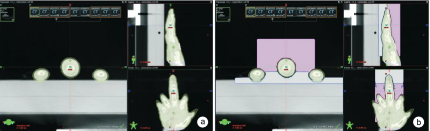
The acquired images were used in Treatment Planning System (TPS) to delineate Gross Tumor Volume (GTV), patient body and virtual 3D bolus structure. The GTV was delineated by a radiation oncologist to fully covered the tumor site. As Fig. 1 Shown, the virtual bolus was designed as a box shape which cover the tumor site and exclude 2 mm expansion from body structure based on patient CT images with HU threshold value, −400 HU, to avoid compression on the patient skin due to production error.
To give sufficient build-up and skin surface dose with 6 MV photon beam, 3 cm average thickness from patient skin surface was applied.
The design of virtual bolus was confirmed by a radiation oncologist and a medical physicist. The virtual bolus was divided into two parts, upper side and lower side, in order to care the treatment lesion and easy treatment set-up.
To minimize the air gap between the skin surface and the bolus Vaseline was fulfilled.
2. 3D bolus printing and treatment planning
To reduce the production time, we make two parts of the 3D bolus simultaneously using the Maker bot (New York, United States) Replicator 2nd generation 3D printer and
a b
Fig. 1. Design procedure of the 3D virtual bolus in TPS. (a) The contour is delineated with 2 mm expansion from the body structure, (b) the virtual bolus is designed as a box shape which cover the treatment lesion and exclude the contour drawn previously and divided by two parts to reduce the production time.
ANATZ (Seoul, Korea) 3D printer, the printing time was about 16 hours each.
To create a 3D bolus, the virtual bolus structure designed in TPS was extracted as a Digital Imaging and Communications in Medicine (DICOM) file and imported to 3D slicer (version 4.6.2) program.9) The smoothing function of the slicer pro- gram was used to remove rough surface and unwanted pro- truding part of the extracted structure file. After smoothing, the structure file was transformed as Stereo lithography (STL) file, which is generally used for 3D printing. Each printer can fabricate objects using Polylatic Acid (PLA) and Acrylonitrile Butadiene Styrene (ABS) as filament material. In this study the PLA was chosen since PLA is a non-toxic plant material and has the advantage of almost no shrinking upon cooling which ensures that geometrical integrity is maintained during printing.
Since 3D bolus is a virtual structure in TPS, we need to determine the relative electron density value for the bolus structure to calculate the treatment plan. We measured the average relative electron density from the acquired CT images of printed bolus as HU value and the HU values were assigned to virtual bolus structure in TPS. The average relative electron densities to water for each bolus made by the maker bot and ANATZ printer were 1.0532 and 0.9933.
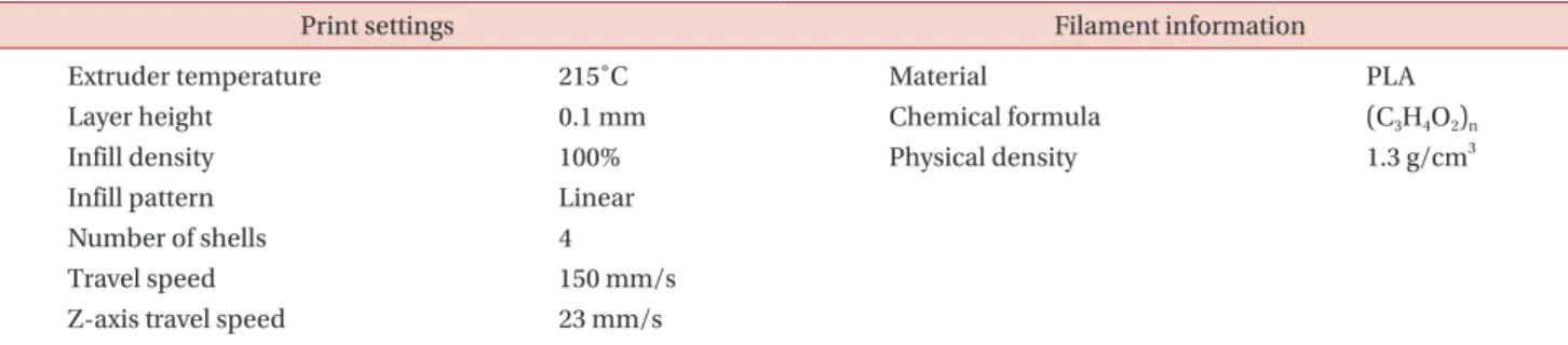
The production conditions and properties of the filaments used are shown in Table 1.
The treatment plan using AP/PA treatment technique with 6 MV photon beam was calculated with a 2.5 mm grid size to allow a dose of 250 cGy to the Planning Tumor Volume (PTV) using the Analytical Anisotropic Algorithm of EclipseTM (Version 13.6, Varian Medical Systems, Palo Alto, Calif.).
3. Printed 3D bolus evaluation
In order to evaluate the suitability of the virtual bolus, we printed the patient finger phantom and acquire CT image while the finger phantom is placed inside the printed bolus with same set-up as real patient treatment. Then the treatment plan is applied on the CT image with two different structure sets. One structure set has GTV and body structure while another structure set has GTV, body and bolus with assigned HU value. Dose distributions difference caused by two different bolus structures are compared to evaluate the inhomogeneity effect of bolus material.
The absolute film dosimetry was also performed to measure the plan accuracy. The printed finger phantom was divided into two pieces to place EBT film in it.
The finger phantom with printed bolus and EBT film was irradiated with same beam parameters as patient treatment. The film was scanned in 18 hours and gamma evaluation was performed using filmQATM.10)
The American Association of Physicians in Medicine Task Group 40 recommended that clinics should have access to Thermos Luminescence Dosimeter (TLD) or other in-vivo dosimetry system in order to prevent major treatment errors.11) The dosimetric accuracy was evaluated by Optically Stimulated Luminescent Dosimeter (OSLD) measurement at patient treatment. The patient's skin surface dose measurement using an OSLD, which was used for the nano-dots dosimeter (Landauer, Inc., Glenwood, IL), was verified in the previous study.12) The point dose measurement during the patient treatment using the OSLD was implemented at the upper and lower position of treatment lesion.
The used films and OSLDs were calibrated for the same
Table 1. 3D printing conditions and physical properties of the PLA filament.
Print settings Filament information
Extruder temperature 215˚C Material PLA
Layer height 0.1 mm Chemical formula (C3H4O2)n
Infill density 100% Physical density 1.3 g/cm3
Infill pattern Linear
Number of shells 4
Travel speed 150 mm/s
Z-axis travel speed 23 mm/s
photon energy used in the treatment. As the treatment progressed, the affected area became thinner and the thickness of the fingers became thinner, so that the air gap became wider than at the beginning of the treatment.
Vaseline was used to fill the air gap.
Results
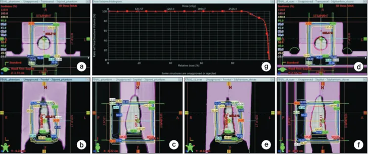
Fig. 2 shows the comparison results of the dose difference between treatment plan of assigned average HU value of the 3D printed bolus to virtual 3D structure at TPS with treatment plan of actual 3D printed bolus. As shown in the Fig. 2, the treatment plan with the virtual bolus structure and the treatment plan with the actual phantom
showed the 0.2% mean dose difference and 0.3% max dose difference in the PTV lesion. In Fig. 3a, b show the patient set-up with printed bolus and Fig. 3c shows 4 month follow up result. The complete local response was confirmed by radiation oncologist.
The dosimetric accuracy of the treatment plan was evaluated with gamma evaluation method with radiochro- mic film placed inside finger phantom covered by printed bolus. The passing rate of gamma evaluation, 2%, 2 mm criteria, was 99.6%.
The surface dose was measured with OSLDs during the treatment to verify the treatment plan. The surface dose was measured three times on the anterior and posterior surface of the treatment lesion. The dose difference between
a
b c
d
e f
g
Fig. 2. The isodose lines difference of the treatment plan in (a) axial, (b) coronal and (c) sagittal view for actual treatment plan without applying HU value to bolus structure. The isodose lines difference of the treatment plan in (d) axial, (e) coronal and (f) sagittal view for actual treatment plan with applying HU value to bolus structure. (g) DVH difference between two plans. Box is represent the without HU assign plan and triangle is represent the HU assigned plan.
a b c
1
2
Fig. 3. (a) A series of clinical photographs of patient before treatment set-up, (b) after treatment set-up, (c) patient picture before treatment and 4 months after treatment.
the treatment plan with the OSLD measurement were 0.3±4.2% at anterior side and 2.1±3.2% at posterior side. The OSLD measurement results were shown at Table 2.
Discussion
In radiotherapy using photon beams, sufficient thickness of build-up material is required to treat the patient's skin surface, and build-ups are made using flat boluses commonly used in general. However, the use of a flat- shaped bolus to create irregular build-up materials can not adequately cover the patient's skin surface and creates an air layer between the bolus and the patient's skin. And it has a disadvantage that the set-up between treatments can vary and the shape changes easily depending on the patient's movement during treatment too.
In this study, in order to overcome the disadvantages of conventional method, 3D printing technique was used to create customized bolus according to the patient and used for MF treatment. Since the bolus using 3D printing technique can be designed and printed to match the shape of the irregular patient's skin accurately, it is more accurate than the conventional flat bolus method. In addition, the 3D bolus printed by the Fused deposition modeling (FDM) method using PLA filament with no flexibility has the advantage of being able to serve as a fixing tool to prevent the intra and inter movement error during the treatment and to be easily stored. During the course of radiation therapy, the patient's set-up is first checked using a laser in the treatment room and secondary confirmation is performed using an MV and kV imaging device. In the case of using 3D printing bolus, the set-up is carried out using fixed bolus, so the set-up can be done in less time than the conventional method. However, considering the patient treatment will start after 2~3 days from the CT
simulation, the bulky bolus increases the production time in proportion to the volume of the bolus and it may take additional time to start the treatment. Also, if the patient does not match the lesion due to biomechanical changes, buoyancy or weight loss, the bolus should be reprinted.
The most cost of patient specific bolus using 3D printing technique is for filament materials, with the exceptions of printer equipment and human labor and it was about $16 for 1 patient specific bolus.
As can be seen from the plan comparison with two different bolus structure setting results, the difference of the HU values causes an average dose difference of 0.2%.
For more accurate treatment planning, it is appropriate to substitute the mean HU value of the beam path into the virtual bolus structure. This result indicates that the in homogeneity in printed bolus is neglectable. As Fig. 3 shown, we follow up the patient treated with the 3D printed bolus treatment plan for 4 months and the patient was well treated.
When applying the 3D printed bolus in a TPS, it may be more accurate to assign measured or calculated density of a 3D printed bolus. However, in this study, HU value acquired from CT image is used since the AP/PA technique is a relatively simple radiation therapy method. In this case, it is easy to find the dose inaccuracy and apply the dose correction factor. We even confirmed that the effect of the inaccuracy is not great by the pretreatment QA. (The absolute film measurement, 2%, 2 mm criterion gamma passing rate 99.6%) This method has the advantage that the patient does not need to take CT once again after the bolus is made and it could be applied if we do not know the exact density of the 3D printed bolus.
In 3D printing, the production time increases in propor- tion to the volume to be printed. In the case of the bolus printed in this study, two 3D printers was used about 15 hours of production time each, which means that more Table 2. The in-vivo dosimetry result with the OSLD measurement.
Expected dose @ TPS : 260 cGy (Anterior & posterior side both)
OSLD position OSLD measurement result Average dose
(cGy)
S.D (cGy)
Difference to 1st (cGy) 2nd (cGy) 3rd (cGy) TPS
Anterior side of PTV 250.4 260.6 271.2 260.7 ±10.4 0.3%
Posterior side of PTV 257.2 273.8 265.5 265.5 ±8.3 2.1%
Average dose (cGy) 253.8 267.2 268.4 263.1 1.2%
than 30 hours of production time is required at single 3D printer. Therefore, sufficient time is required for making the patient specific bolus using 3D printing technique.
Conclusion
In this study, we treated Mycosis fungoides patient with patient specific bolus using 3D printing technique.
The 3D printed bolus has the advantages of easy patient set-up, comfort of patient, function of build-up and immobilization. The accuracy of treatment plan was verified by pretreatment QA and in-vivo dosimetry. The QA results and 4 month follow up result shows the radiation treatment using 3D printing bolus is feasible to treat irregular patient skin.
Acknowledgements
This research was supported by the National Research Foun- dation of Korea (NRF) grant funded by the Korea govern ment (MSIP) (2014R1A1A2058154 and NRF-2016R1C1B2014792).
Conflicts of Interest
The authors have nothing to disclose.
Availability of Data and Materials
All relevant data are within the paper and its supporting information files.
References
1. HOPPE, Richard T. Mycosis fungoides: radiation therapy.
Dermatologic therapy. 2003;16:347-354.
2. SCHOLTZ, W. Ueber den Einfluss der Röntgenstrahlen auf die Haut in gesundem und krankem Zustande. Archiv für
Dermatologie und Syphilis. 1902;59:421-446.
3. MICAILY, Bizhan, et al. Radiotherapy for unilesional mycosis fungoides. International Journal of Radiation Oncology Biology Physics. 1998;42:361-364.
4. HOPPE, R. T., et al. Electron-beam therapy for mycosis fungoides: the Stanford University experience. Cancer treatment reports. 1979;63:691-700.
5. MAJITHIA, Lonika, et al. Treating Cutaneous T-Cell Lymphoma with Highly Irregular Surfaces with Photon Irradiation Using Rice as Tissue Compensator. Frontiers in oncology. 2015;5.
6. Kyoungjun Yoon, et al. Development of new 4D phantom model in respiratory gated volumetric modulated arc therapy for lung SBRT. Progress in Medical Physics.
2014;25:100-109.
7. Sang Gyu Ju, et al. New technique for developing a proton range compensator with use of a 3-dimensional printer.
International Journal of Radiation Oncology Biology Physics. 2014,88: 453-458.
8. Jin-Suk HA, et al. Customized 3D Printed Bolus for Breast Reconstruction for Modified Radical Mastectomy (MRM).
Progress in Medical Physics. 2016;27:196-202.
9. Holtzer NA, Galis J, Paalman MI, Heukelom S. 3D printing of tissue equivalent boluses and molds for external beam radiotherapy. In: Estro 33, Vienna.
10. BORCA, Valeria Casanova, et al. Dosimetric characte- rization and use of GAFCHROMIC EBT3 film for IMRT dose verification. Journal of applied clinical medical physics. 2013;14:158-171.
11. KUTCHER, Gerald J., et al. Comprehensive QA for radi- ation oncology: report of AAPM radiation therapy commi- ttee task group 40. Medical physics. 1994;21:581-618.
12. YUSOF, Fasihah Hanum, et al. On the use of optically stimulated luminescent dosimeter for surface dose measurement during radiotherapy. PloS one. 2015;10:
e0128544.