http://dx.doi.org/10.7316/khnes.2012.23.1.034
고분자 전해질 연료전지에서 탄소복합 기체확산층의 제조와 특성분석
심중표1†ㆍ한춘수1ㆍ선호정2ㆍ박경세3ㆍ이지정4ㆍ이홍기4
1군산대학교 나노화학공학과, 2군산대학교 신소재공학과, 3군산대학교 화학과,
4우석대학교 수소연료전지 및 응용부품기술 지역혁신센터
Preparation and Characterization for Carbon Composite Gas Diffusion Layer on Polymer Electrolyte Membrane Fuel Cells
JOONGPYO SHIM1†, CHOONSOO HAN1, HOJUNG SUN2, GYUNGSE PARK3, JIJUNG LEE4, HONGKI LEE4
1Department of Nano & Chemical Engineering, Kunsan National University, Jeonbuk, 573-701, Korea
2Department of Material Science & Engineering, Kunsan National University, Jeonbuk, 573-701, Korea
3Department of Chemistry, Kunsan National University, Jeonbuk, 573-701, Korea
4Fuel Cell Regional Innovation Center, Woosuk University, Jeonbuk, 565-701, Korea
Abstract >> Gas diffusion layers (GDLs) of carbon composite type in polymer electrolyte fuel cells were prepared by simple and cheap manufacturing process. To obtain the carbon composite GDLs, carbon black with polymer binder was mixed in solvent, rolled to make sheet, and finally heat-treated at 340℃. The performance of fuel cell using composite GDLs was changed by PTFE content. The physical properties of composite GDLs for pore, conductivity and air permeability were analyzed to compare with the variation of fuel cell performance. The conductivity of composite GDLs was very similar to carbon paper as commercial GDL but pore properties and air flux were considerably different. The porosity, PTFE content and conductivity for composite GDLs did not have an influence on the cell performance much. The increase of pore diameter and air flux led to enhance cell performance.
Key words : Polymer electrolyte membrane fuel cell(고분자 전해질 연료전지), Gas diffusion layer(기체 확산층), Carbon composite(탄소복합체), Electrode(전극), porosity(기공도)
†Corresponding author : [email protected]
[ 접수일 : 2012.1.27 수정일 : 2012.2.15 게재확정일 : 2012.2.24 ] Copyright ⓒ 2012 KHNES
1. Introduction
Polymer electrolyte membrane fuel cells (PEMFCs) are good power sources for electronic devices because of their high efficiency, high power density, low
emissions, low operation temperature, and low noise1). Although PEMFCs have many advantages, there are still many obstacles to commercialization such as the high cost of materials and low durability. A membrane electrode assembly (MEA), which is the heart of a PEMFC, consists of a catalyst, a polymer electrolyte membrane and a gas diffusion layer (GDL).
The functions of the GDL are to act as a gas
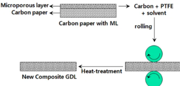
Fig. 1 Concept for manufacturing process of carbon composite GDL
conductivity3), appropriate hydrophobicity4,5), high air permeability6) and sufficient mechanical strength7-9). GDLs are typically carbon-based materials, and usually in cloth or paper form10,11). They are manufactured using huge and high-cost processes of carbonization or fabrication. Only a few researches studies on the preparation of GDLs without carbon paper or carbon cloth have been reported. Hayashi et al.12) and Chen- Yang et al.13) reported a process for obtaining diffusion media from a combination of carbon materials and polytetrafluoroethylene (PTFE). They showed that the performance of a PEMFC containing such GDLs changed depending on the composition of the carbon materials and PTFE.
In this study, the carbon composite GDLs were prepared by mixing carbon black with a polymer binder, namely PTFE. The main properties of GDLs that affect fuel cell performance are hydrophobicity, electrical conductivity, pore size distribution, and air permeability. We investigated the role of each of these properties in cell performance.
2. Experimentals
To prepare the carbon composite GDL, carbon black (Vulcan XC-72, Cabot, Boston, MA, USA) and a PTFE suspension (60% solid, DuPont, Wilmington, DE, USA) were mixed in a water/isopropyl alcohol (IPA) solvent. The solution was agitated to make a paste-like gum, and then rolled on a glass plate until it formed a thin sheet. The carbon composite GDL sheet were dried at 80℃ for 6h and then heat-treated at 340℃ for 1h to remove surfactant contained in the PTFE suspension. The GDL thickness was from 150
to 200 mm and its PTFE content was from 20%
(PF2) to 50% (PF5). Fig. 1 shows the manufacturing process for the carbon composite GDL.
The weights of carbon and binder were measured by thermal gravimetric analysis (TGA; SDT Q600, TA Instrument, New Castle, DE, USA), and the surface morphologies of the GDLs were observed by scanning electron microscopy (SEM; S-4800, Hitachi, Tokyo, Japan). The porosity and pore size distribution were measured using mercury porosimeter (AutoPore 9500, Micromeritics, Norcross, GA, USA).
Air flux through a plane (along the z direction) of the GDLs was measured with a laboratory-made instrument using the Gurley method (ASTM D737). This instru- ment, a permeometer, measured air flow per minute at 1.27 cm (0.5 inch) water pressure drop between the gas inlet and outlet. Single-phase flow through a porous medium is described by Darcy’s law14):
(1)
where K is the absolute permeability of the porous material, μ is the viscosity (1.85 x 10⁻⁵ Pa・s for air) of the flowing fluid, υ is the superficial velocity of the fluid and P is the pressure. Solution of Darcy’s law for the one-dimensional flow of a compressible fluid results in the following equation15):
Fig. 2 TGA of carbon composite GDL and carbon paper in air
(2)
where Pin is the inlet pressure, Pout is the outlet pressure, L is the length of the GDL, R is the universal gas constant, T is the temperature, MWair is the molecular weight of air and m’ is the mass flux through the GDL.
The through-plane resistance was measured using DC power supply (Jhp-1500A, Jin Heung Scientific Co, Korea) using Au-coated Cu plates. The GDL was set between the two plates which were connected to the power supply and a current-voltage multimeter (34401A, Agilent, Santa Clara, CA, USA). The measured resistance included the total resistance of the bulk material and the interface contact between the GDL and the metal plate. We measured the resistances of GDLs with two and four sheets compressed at 25 kgf/cm2 and then, calculated the resistance, ρ (Ωcm), using the following equation, which was proposed by the New Energy and Industrial Technology Development Organization (NEDO) and Mitsubishi Electric:
(3)
where R4 and R2 are the resistances for two and four sheets, respectively, A is the electrode area and t is the GDL thickness.
MEAs were prepared as follows16), using a catalytic ink consisting of Pt/C (20%, Johnson Matthey, London, UK), Nafion (5% solution, DE521, DuPont, Wilmington, DE, USA) and IPA. The solid particles of Pt/C were dispersed uniformly by ultrasonication and the particles were connected by the Nafion polymer. The catalytic ink was sprayed on the GDL until the Pt loading reached 0.3 mg/cm2. The electrode size was 25 cm2 and dried at 60℃ for 3h to remove solvents. To prepare
the MEA, two electrodes were sandwiched with a Nafion 112 membrane (EW 1100, DuPont, Wilmington, DE, USA) and hot-pressed at 120℃ and 200 bar for 2min. Before hot-pressing, the Nafion 112 was treated using a well-known membrane cleaning procedure17). The fuel cell was operated at 80℃ and humidified hydrogen and air were supplied to the cell. The temperatures of the hydrogen and the air were 90 and 70℃, respectively, and the gas flows were controlled at 1.5 and 3.0 excess, respectively. The fuel cell performance was measured in constant current mode from open circuit voltage (OCV) to 0.3V.
3. Results and Discussion
The PTFE content of the GDL is a very important factor with respect to hydrophobic properties; these properties prevent water-flooding in the GDL and vent vapor to the outside of the GDL. As show in Fig. 2, TGA was carried out in an air atmosphere to determine the PTFE content and compare it with that in a commercial GDL. Weight loss for all the GDLs started at around 530℃, and this was assigned to
Fig. 3 Cell performance of carbon composite GDL and carbon paper as a function of mixing ratio
(a) (b)
(c) (d)
(e) (f)
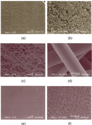
Fig. 4 SEM images of carbon composite GDL (CB8/PF2) (a,b), carbon paper (c,d) and microporous layer of carbon paper (e,f)
PTFE decomposition18,19). The second weight losses for the carbon composite GDLs were observed above 600℃, which is the region for carbon oxidation20). However, the second weight loss of carbon paper occurs above 700℃ because its carbon material consists of graphitized carbon fibers. Finally all the materials were burned above 750℃ for the carbon composite GDL and 850℃ for the carbon paper. The PTFE loading in the GDL was confirmed from the weight loss induced by the decomposition of PTFE at around 550℃ in air.
Fig. 3 shows the fuel cell performances of MEAs containing carbon composite GDLs and two commercial carbon papers. All the carbon composite GDLs showed lower performances than those of commercial carbon paper. The PTFE content in the carbon composite GDLs had a significant effect on cell performance.
The cell performance increased with increasing PTFE content until 40wt% PTFE. A low PTFE content may induce water-flooding phenomena in the GDL and prevent reactant gases from diffusing into the catalyst layer4,21). The performance of the GDL with 50%
PTFE under the high current region, 0.3~0.5V of
cell voltage, was lower than that with 40% PTFE because too high a PTFE loading may increase the resistance of the GDL.
SEM images of a carbon composite GDL (CB8/
PF2) and carbon paper are shown in Fig. 4. The surface morphology of the carbon composite GDL looks very smooth and dense compared with that of the carbon paper. It seems very similar to the micro porous layer (MPL) on carbon paper produced by E-TEK22). It was estimated that its pore size was much very smaller than that of carbon paper, and similar to that of an MPL.
Fig. 5 shows the pore size distribution of the carbon composite GDL, carbon paper and carbon paper with an MPL. The main pores of the carbon paper were in the range 10 - 100 μm, which were formed by the
Fig. 5 Pore size distributions of carbon composite GDL, carbon paper and carbon paper with MPL
Fig. 6 Conductivity of carbon composite GDL, carbon paper and carbon paper with MPL at 25 kgf/cm2
internal space between carbon fibers. The carbon paper with an MPL had two main pore types; pores in the range 0.04 - 0.5 μm in the MPL and pores in the range 10 - 100 μm in the carbon paper, the same as those in the other carbon paper. However, the carbon composite GDL had pores in the range 0.01 - 3.0 μm.
Pore diameter above 50 nm is assigned to macro-pore, that of 2 - 50 nm is assigned to meso-pore and that less than 2 nm is assigned to micro-pore23). The sharp peak for the pore between 0.01 and 0.5 μm in the carbon composite GDL may be the result of pores formed by the spaces in agglomerated primary carbon particles, and the broad one in the range 0.5 - 3.0 μm may result from pores formed by the interspaces between the primary particles24,25). Diffusion of gas in porous media occurs mainly through Bulk and Knudsen diffusion processes. The effective diffusion coefficient in the Bulk diffusion regime, which is assigned to pore diameters above 7 μm, is three orders higher than that in the Knudsen diffusion regime for pores below 7 nm26). Larger pores therefore enhance mass transport through porous media. In the commercial carbon paper, pores above 10 μm were dominant in
the pore distribution, but the pores in the carbon paper with an MPL were well distributed in all ranges.
However, the carbon composite GDL had pores in the micro-pore regions. This means that bulk diffusion for gas transport through large pores is deficient in the carbon composite GDL.
The role of the GDL with respect to electrical properties is to supply electrons, which will be produced or consumed at the catalytic layer, to or from a bipolar plate. The conductivity of the GDL is therefore a very important factor. Fig. 6 shows the through- plane conductivities of the carbon composite GDLs, carbon paper and carbon paper with an MPL; these were measured by the two-probe method. The GDL conductivity decreased with increasing PTFE content showing a linear relationship with the portion of non- conductor in the GDL. Carbon paper showed a very high conductivity as a result of the high conductivity of carbon fibers. However, the conductivity of carbon paper with an MPL was very similar to that of the carbon composite GDL with 20% PTFE despite the MPL on the carbon paper. This may be the reason for the composition of MPL being the same as that
Fig. 7 Air flux of carbon composite GDL, carbon paper and carbon paper with MPL
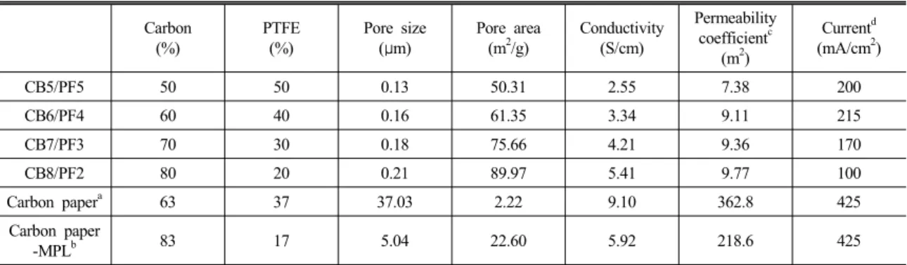
Table 1 Physical properties of carbon composite GDLs and carbon papers
Carbon (%)
PTFE (%)
Pore size (μm)
Pore area (m2/g)
Conductivity (S/cm)
Permeability coefficientc
(m2)
Currentd (mA/cm2)
CB5/PF5 50 50 0.13 50.31 2.55 7.38 200
CB6/PF4 60 40 0.16 61.35 3.34 9.11 215
CB7/PF3 70 30 0.18 75.66 4.21 9.36 170
CB8/PF2 80 20 0.21 89.97 5.41 9.77 100
Carbon papera 63 37 37.03 2.22 9.10 362.8 425
Carbon paper
-MPLb 83 17 5.04 22.60 5.92 218.6 425
a: Toray 060ST (E-TEK). b: LT 1200 (E-TEK), c: x10-12, d: at 0.5V
Fig. 8 Physical properties of carbon composite GDL as a function of cell voltage
of the carbon composite GDL.
The through-plane air fluxes of the carbon composite GDLs were measured using a laboratory-made apparatus.
Fig. 7 shows the air fluxes of various GDLs as a function of PTFE content. Commercial GDLs, which are based on carbon fibers, had very high air fluxes compared with those of carbon composite GDLs. The PTFE binder decreased the air fluxes in the carbon composite GDLs because PTFE particles block the passage of gases through the GDLs27). The permeability coefficients of the GDLs were calculated using Darcy’s law; the results are shown in Table 1. These results
are different from the values reported in the literature.
Gostick et al.28) found the through-plane permeability coefficients for SGL, Ballard and Toray carbon papers to be in the range 5.7 x 10⁻¹² to 37.4 x 10⁻¹² m2, which are approximately 10 orders lower than those of the carbon composite GDLs. These differences may be caused by different measurement methods and apparatus.
Table 1 shows a summary of the physical properties for various GDLs and Fig. 8 shows the relationship between physical properties and cell performance (cell voltage at 0.2 A/cm2). The porosity, PTFE content
and conductivity did not have much influence on the cell performance. Increase in pore diameter and air flux enhanced cell performance, but an increase in the pore area had the opposite effect. We concluded that increasing the pore diameter and air flux improved the fuel cell performance; Prasanna et al. also reported similar results29). If these carbon composite GDLs are used in fuel cells operated at high current (>1 A/cm2), the conductivity and PTFE content are also important factors with regard to cell performance30,31).
4. Conclusions
The characteristics of carbon composite GDLs for PEMFCs were investigated in terms of fuel cell per- formance and physical properties. The carbon composite GDLs were obtained by mixing carbon black and a polymer binder in a solvent, rolling to form a sheet, and finally heat-treating at 340℃. The performances of fuel cells using carbon composite GDLs were changed by changing the PTFE content. The conductivities of the carbon composite GDLs were very similar to that of a carbon paper, commercial GDL but the pore properties and air fluxes were significantly different.
Macro-pores do not exist in the carbon composite GDLs, unlike the situation for carbon paper, and this may decrease mass transport though the GDL. The physical properties of the carbon composite GDLs were analyzed to determine their effects on fuel cell performance. The porosities, PTFE contents and con- ductivities for the carbon composite GDLs did not have much influence on the cell performance. Increase in pore diameter and air flux enhanced cell performance because of improved gas transport through the GDLs.
Acknowledgement
This work was financially supported by the Program
of Regional Innovation Center at Woosuk University which was conducted by the Ministry of Knowledge Economy of the Korean Government.
References
1. EG&G Technical Services, Inc., “Fuel Cell Hand- book”, U.S. Department of Energy, West Virginia, p1-12, 2004
2. S. Litster, G. McLean, “PEM fuel cell electrodes”, J. Power Sources, Vol. 130, 2004, p. 61.
3. S. Park, J.-W. Lee, B.N. Popov, “Effect of carbon loading in microporous layer on PEM fuel cell per- formance”, J. Power Sources, Vol. 163, 2006, p.
357.
4. G.-G. Park, Y.-J. Sohn, T.-H. Yang, Y.-G. Yoon, W.-Y. Lee, C.-S. Kim, “Effect of PTFE contents in the gas diffusion media on the performance of PEMFC”, J. Power Sources, Vol. 131, 2004, p.
182.
5. J. Lobato, P. Canizares, M.A. Rodrigo, C. Ruiz- Lopez, J.J. Linares, “Influence of the Teflon loading in the gas diffusion layer of PBI-based PEM fuel cells”, J. Appl. Electrochem., Vol. 38, 2008, p. 793.
6. J.P. Feser, A.K. Prasad, S.G. Advani, “Experi- mental characterization of in-plane permeability of gas diffusion layers”, J. Power Sources, Vol. 162, 2006, p. 1226.
7. J. Ge, A. Higier, H. Liu, “Effect of gas diffusion layer compression on PEM fuel cell performance”, J. Power Sources, Vol. 159, 2006, p. 922.
8. S. Escribano, J.-F. Blachot, J. Etheve, A. Morin, R. Mosdale, “Characterization of PEMFCs gas diffusion layers properties”, J. Power Sources, Vol. 156, 2006, p. 8.
9. E.-J. Ahn, G.-G. Park, Y.-G. Yoon, J.-S. Park, W.-Y. Lee, C.-S. Kim, “Effect of clamping pressure on surface properties of gas diffusion layer in PEFCs”, J. Kor. Electrochem. Soc, Vol.
membrane fuel cell (PEMFC)”, J. Power Sources, Vol. 107, 2002, p. 5.
11. E. Antolini, R.R. Passor, E.A. Ticianelli, “Effects of the carbon powder characteristics in the cathode gas diffusion layer on the performance of polymer electrolyte fuel cells”, J. Power Sources, Vol. 109, 2002 p. 477.
12. M. Hayashi, T. Sugitani, Y. Asano, US Patent 2005/0173244 A1, 2005.
13. Y.W. Chen-Yang, T.F. Hung, J. Huang, F.L.
Yang, “Novel single-layer gas diffusion layer based on PTFE/carbon black composite for proton exchange membrane fuel cell”, J. Power Sources Vol. 173, 2007, p. 183.
14. F.A.L. Dullien, Porous Media: Fluid Transport and Pore Structure, Academic Press, New York, 1992.
15. J. Geertsma, “Estimating the coefficient of inertial resistance in fluid flow through porous media”, Soc. Pet. Eng. J. Vol. 10, 1974, p. 445.
16. K. Ahn, C. Yang, S. Lee, “A Study on Electro- chemical Characteristics of MEA with Nafion Ionomer Content in Catalyst Layer for PEMFC”, Trans. Kor. Hydrogen New Energy Soc, Vol. 21, 2010, p. 540.
17. D. Weng, J.S. Wainright, U. Landau, R.F.
Savinell, “Electro-osmotic Drag Coefficient of Water and Methanol in Polymer Electrolytes at Elevated Temperatures”, J. Electrochem. Soc, Vol. 143, 1996, p. 1260.
18. D. Antonioli, M. Laus, K. Sparnacci, S. Deregibus, V. Kapeliouchko, G. Palamone, T. Poggio, G.
Zuccheri, R. Passeri, “Thermal and DMA charac- terization of PTFE-PMMA nanocomposites from core-shell nanoparticles”, Macromol. Symp. Vol.
296, 2010, p. 197.
19. “Thermalgravimetric analysis”, TA Instruments.
20. Thermal Analysis Application No HB 451, Mettler
management by a microporous sublayer for PEM fuel cells”, J. Power Sources, Vol. 109, 2002, p.
38.
22. J.-J. Lee, I.-T. Kim, Y. Zhang, H.-K. Lee, J.
Shim, “Comparison of Cell Performance with Physical Properties of Gas Diffusion Layers in PEMFCs”, J. Kor. Electrochem. Soc, Vol. 10, 2007, p. 270.
23. J. Rouquerol, D. Avnir, C.W. Fairbridge, D.H.
Everett, J.H. Haynes, N. Pernicone, J.D.F.
Ramsay, K.S.W. Sing, K.K. Unger, “Recom- mendations for the characterization of porous solids”, Pure. Appl. Chem., Vol. 66, 1994, p.
1739.
24. M. Watanabe, M. Tomikawa, S. Motoo, “Ex- perimental analysis of the reaction layer structure in a gas diffusion electrode”, J. Electroanal.
Chem., Vol. 195, 1985, p. 81.
25. M. Uchida, Y. Aoyama, N. Eda, A. Ohta,
“Investigation of the Microstructure in the Catalyst Layer and Effects of Both Perfluorosul- fonate Ionomer and PTFE-Loaded Carbon on the Catalyst Layer of Polymer Electrolyte Fuel Cells”, J. Electrochem. Soc., Vol. 142, 1995, p. 4143.
26. R.H. Perry, D.W. Green, “Perry’s Chemical Engineers’ Handbook”, 7thed., McGrawHill, 1997, p5.
27. H. Jeon, T. Cho, W. Choi, “Water Repellent Coating of Carbon Cloth with Different Size PTFE and Gas Permeabilities”, Trans. Kor.
Hydrogen New Energy Soc, Vol. 21, 2010, p.
313.
28. J.T. Gostick, M.W. Fowler, M.D. Pritzker, M.A.
Ioannidis, L.M. Behra, “In-plane and through- plane gas permeability of carbon fiber electrode backing layers”, J. Power Sources, Vol. 162, 2006, p. 228.
29. M. Prasanna, H.Y. Ha, E.A. Cho, S.-A. Hong,
I.-H. Oh, “Influence of cathode gas diffusion media on the performance of the PEMFCs”, J.
Power Sources, Vol. 131, 2004, p. 147.
30. L. Giorgi, E. Antolini, A. Pozio, E. Passalacqua,
“Influence of the PTFE content in the diffusion layer of low-Pt loading electrodes for polymer
electrolyte fuel cells”, Electrochim. Acta, Vol.
43, 1998, p. 3675.
31. C. Lim, C.Y. Wang, “Effects of hydrophobic polymer content in GDL on power performance of a PEM fuel cell”, Electrochim. Acta, Vol. 49, 2004, p. 4149.