OSP 표면처리된 FR-4 PCB기판과 Sn58%Bi 복합솔더 접합부의 미세조직 및 접합강도에 미치는 Sn-MWCNT의 영향
박현준·이충재·민경득·정승부† 성균관대학교 신소재공학과
Effect of Sn Decorated MWCNT Particle on Microstructures and Bonding Strengths of the OSP Surface Finished FR-4 Components Assembled with
Sn58%Bi Composite Solder Joints
Hyun-Joon Park, Choong-Jae Lee, Kyung Deuk Min, and Seung-Boo Jung† School of Advanced Materials Science and Engineering, Sungkyunkwan University,
2066, Seobu-ro, Jangan-gu, Suwon-si, Gyeonggi-do 16419, Korea
(Received December 12, 2019: Corrected December 24, 2019: Accepted December 29, 2019)
초 록: 전자제품에서 사용되던 Sn-Pb계 솔더합금은 RoHS, WEEE, REACH 등의 환경규제에 의해 무연솔더합금(Pb free solder alloy)으로 빠르게 대체되고 있다. 그 중에서도 Sn58%Bi(in wt.%) 합금은 융점이 낮고 Sn-Pb계 합금에 비해 기계적특성이 우수하여, 전자제품 솔더합금으로 사용하기 위한 연구가 진행되고 있다. 그러나 Sn58%Bi 솔더합금은 구성 원소인 Bi의 취성으로 인해 기계적인 신뢰성이 저하되는 문제를 개선할 필요가 있다. 따라서 본 연구에서는 다양한 함량 의 Sn-MWCNT (multiwalled carbon nanotube) 입자를 첨가한 Sn58%Bi 복합솔더를 제조한 후, OSP처리된 FR-4 기판 및 FR-4 컴포넌트를 리플로우(reflow) 횟수를 1회부터 7회까지 진행하였다. 접합시편의 접합강도 및 파괴에너지는 전단 시험(die shear test)을 통해 측정하였고, 주사전자현미경(scanning electron microscope, SEM)으로 미세조직 및 파괴모드 를 분석하였다. Sn-MWCNT 첨가에 의해 Sn58%Bi 복합솔더 접합부에서 조직 미세화가 관찰되었고, 함량이 0.1 wt.%일 때 접합강도와 파괴에너지는 각각 20.4%, 15.4% 만큼 증가하였다. 또한 파단면에서 연성파괴(ductile failure) 영역이 관 찰되었으며, F-x(force-displacement to failure) 그래프를 통해 Sn-MWCNT의 첨가가 복합솔더의 연성(ductility)을 증가 시킨 것을 확인할 수 있었다.
Abstract: Sn-Pb solder alloys in electronics rapidly has been replaced to Pb free solder alloys because of various environmental regulations such as restriction of hazardous substances directive (RoHS), European Union waste electrical, waste electrical and electronic equipment (WEEE), registration evaluation authorization and of chemicals (REACH) etc.
Because Sn58%Bi (in wt.%) solder alloy has low melting point and higher mechanical properties than that of Sn-Pb solder, it has been studied to manufacture electronic components. However, the reliability of Sn58%Bi solder could be lowered because of the brittleness of Bi element included in the solder alloy. Therefore, we observed the microstructures of Sn58%Bi composite solders with various contents of Sn-decorated multiwalled carbon nanotube (Sn-MWCNT) particles and evaluated bonding strength of the FR-4 components assembled with Sn58%Bi composite solder. Also, microstructures and bonding strengths of the Sn58%Bi composite solder joints were evaluated with the number of reflows from 1 to 7 times, respectively. Bonding strengths and fracture energies of the Sn58%Bi composite solder joints were measured by die shear test. Microstructures and fracture modes were observed with scanning electron microscope (SEM).
Microstructures in the Sn58%Bi composite solder joints were finer than that of only Sn58%Bi solder joint. Bonding strength and fracture energy of Sn58%Bi composite solder including 0.1 wt.% of Sn-decorated MWCNT particles increased up to 20.4% and 15.4% at 5 times in reflow, respectively.
Keywords: Sn58%Bi composite solder, multiwalled carbon nanotube (MWCNT), Microstructure, Intermetallic compound (IMC), bonding strength, fracture energy
†
Corresponding author E-mail: [email protected]
© 2019, The Korean Microelectronics and Packaging Society
This is an Open-Access article distributed under the terms of the Creative Commons Attribution Non-Commercial License(http://creativecommons.org/
licenses/by-nc/3.0) which permits unrestricted non-commercial use, distribution, and reproduction in any medium, provided the original work is
properly cited.
하이브리드(hybrid) 및 복합솔더(composite solder) 개발에 대한 연구가 현재까지 진행되고 있다.5-7) 특히 SnBi계 합 금은 융점이 낮아 저온공정이 가능하다는 장점과 SnPb계 합금에 비해 기계적특성(mechanical property)이 우수한 것으로 알려져 있지만, SnBi계 솔더의 미세조직 내에 분 포하는 Bi의 취성으로 발생되는 문제를 해결하고, 내충 격 신뢰성을 향상시키는 것이 시급한 상황이다.8,9)
따라서, Lin 등은10) TiO2 나노분말을 솔더합금의 제 2의 강화상(reinforcement)으로 첨가하여 SnPb 솔더합금의 조 직 미세화로 경도를 향상시켰고, Hu 등은11) Sn58%Bi(in wt.%)에 Al2O3를 첨가하여 기계적특성 및 electromigration 의 거동을 검토하였다. 또한, Zhang 등은12) SnAgCu 나노 입자를 첨가하여 Sn58%Bi 솔더합금의 경도를 향상시켰 다. 위와 같이 다양한 종류의 강화상을 첨가하여 솔더합 금의 기계적인 특성을 향상시킬 수 있으며, 특히 탄소나 노튜브(carbon nanotube, CNT)는 우수한 기계적, 전기적, 열적 특성으로 인해 강화상으로 사용될 수 있는 가능성 이 보고되고 있다.13,14)
CNT는 1991년 Iijima 등에15)의해 발견된 탄소의 동소 체로 원기둥 형태의 나노구조이며, 벽의 결합 숫자에 따 라 단중벽 탄소나노튜브(single walled carbon nanotube, SWCNT)과 다중벽 탄소나노튜브(multi walled carbon nanotube, MWCNT)로 분류된다. MWCNT는 최근 대량 생산기술의 확보로 인해 가격이 저렴하여 복합솔더 (composite solder)의 제조에서 강화상으로 사용될 수 있 는 가능성을 높였다.14,16,17) 그러나, 솔더합금과 MWCNT 는 화학적, 물리적 물성차이가 존재하므로 복합솔더를 제 조할 때 다양한 문제점이 발생한다. 예를 들어, MWCNT 와 솔더합금은 화학적으로 결합하지 않기 때문에 약한 원 자 간의 힘인 Van der Waals 힘으로 결합이 유지될 뿐만 아니라,18) 두 재료 간의 밀도차이로 인하여 솔더내부에 MWCNT 입자를 균일하게 분산하는 것이 매우 어렵다.
Sun 등의 보고에 의하면 MWCNT가 솔더에 첨가된 복합 솔더의 리플로우(reflow) 공정중에 MWCNT가 솔더 표면 에 주로 편석되거나, aggregation 되며 솔더계면에서 보이 드(void) 등이 주로 잔류하는 문제점이 있다.18,19)
따라서, 편석과 aggregation 문제를 해결하기 위하여 MWCNT에 Ag, Ni, Sn 등의 나노 혹은 마이크로 사이
강도를 평가하였으며, 동시에 리플로우 횟수가 접합부의 미세조직과 접합강도에 미치는 영향도 함께 검토하였다.
2. 실험 방법
Fig. 1은 재료 및 시편의 준비와 전단시험의 모식도를 나 타낸다. 본 실험에서는 Cu 전극이 OSP(organic solderability preservative)로 표면처리된 FR-4 PCB기판 및 FR-4 컴포넌 트를 상, 하부에 배치하고 Sn-MWCNT가 첨가된 Sn58%Bi 복합솔더로 접합하여 시편을 제작한 후, 접합부의 미세 조직과 접합강도를 평가하였다. FR-4 PCB기판 상부에 실 장(packaging)된 FR-4 컴포넌트의 두께는 1 mm 면적은 15×15 mm2 이며, 기판과 컴포넌트에는 각각 64개(8×8)의 I/O(input/output) 전극으로 구성되었다. 이때 I/O전극 Cu pad의 사이즈는 380 μm, pitch는 1.6 mm였다.
본 실험에서는 Sn58%Bi 및 Sn-MWCNT 분말과 상용 플럭스(CVP-520, Alpha Inc, Korea)를 페이스트 믹서기 (ARE-310, Thinky Co, Japan)를 사용해 기계적으로 교반 하여 Sn58%Bi 복합솔더 페이스트를 제조하였으며, Sn- MWCNT가 복합솔더 접합부의 미세조직 및 접합강도에 미치는 영향을 분석하기 위해 0, 0.05, 0.1, 0.2 wt.%로 첨 가하였다.
FR-4 PCB기판과 FR-4 컴포넌트를 접합하여 시편을 제 조하는 공정은 다음과 같다. 먼저 Sn58%Bi 복합솔더 페 이스트를 스크린 프린팅(screen printing) 방법을 사용하여 FR-4 PCB기판에 인쇄하였고, 사용된 금속 마스크(metal mask)의 오프닝 사이즈와 두께는 각각 550 μm, 0.15 mm 이다. 다음으로 페이스트가 인쇄된 FR-4 PCB기판 위에 FR-4 컴포넌트를 임시로 부착하고 리플로우 장비(RF- 430-N2, JPL Co, Japan)를 이용하여 접합하였다. 이때, 리 플로우 횟수가 복합솔더 접합부의 미세조직 및 접합강도 에 미치는 영향을 분석하기 위해 1, 2, 3, 5, 7회로 리플로 우를 시행하였으며 리플로우 후 솔더볼의 직경은 약 420 μm였다.
리플로우 공정 후에 SEM(SU8010, Hitachi Co, Japan)를 이용하여 접합부의 미세조직을 관찰하였고, 전단시험장 비(Dage 4000 PXY, DAGE Co, England)를 이용하여 접합 강도를 평가하였다. 이때, 전단시험은 Die shear testing 규
격(Mil-Std-883-2019)을 기준으로 전단높이는 30 μm, 전 단속도는 200 μm/s 조건으로 실시하였다. 전단시험 후에 는 F-x(force-displacement) curve 그래프로 부터 파괴에너 지를 계산하였으며, 파단면을 SEM으로 관찰하여 솔더 접합부의 파괴모드 및 미세조직을 분석하였다.
3. 결과 및 고찰
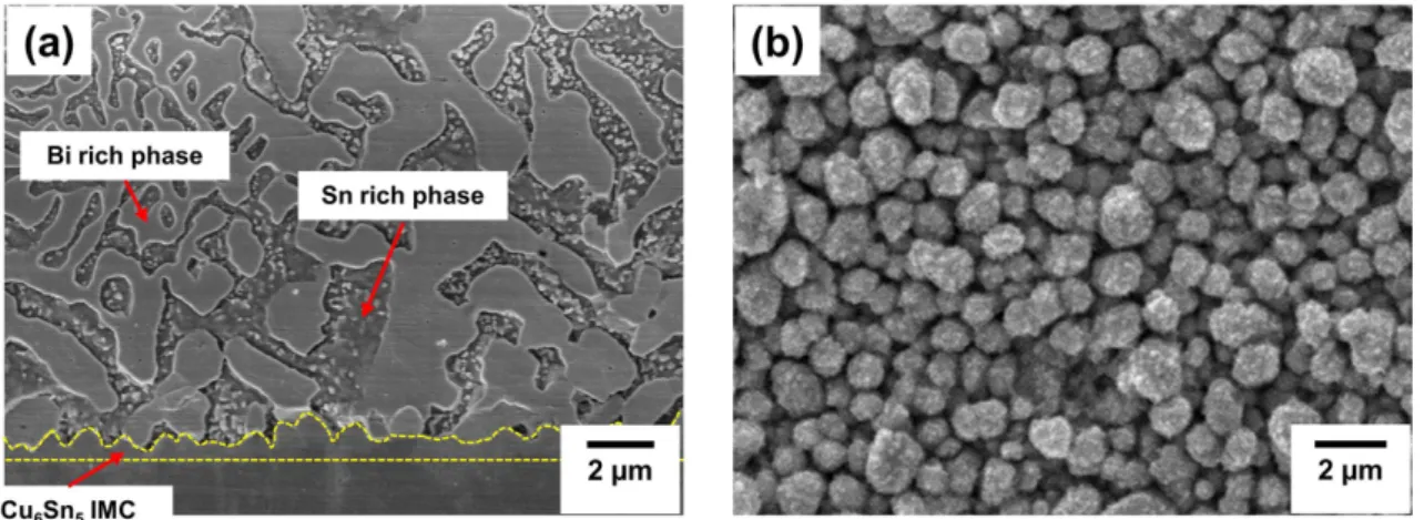
Fig. 2는 접합부의 단면에서 관찰한 Sn58%Bi 복합솔 더의 미세조직 및 OSP 표면처리된 Cu 전극과 계면반응 으로 생성된 IMC(intermetallic compound)의 형상을 나 타낸다. Sn58%Bi 복합솔더의 미세조직은 Sn rich 상과 Bi rich 상으로 이루어진 lamellar 구조가 관측되는데, 이는
Sn58%Bi 솔더가 응고될 때 공정반응(eutectic reaction, L → Sn + Bi)이 발생하기 때문이다.24, 25) 리플로우 공 정 후에 복합솔더와 OSP 처리된 Cu 전극의 계면에서 scallop 타입의 Cu6Sn5 IMC가 관찰되었다. 이때 IMC의 morphology는 솔더합금을 에칭을 통해 제거한 후 위쪽 (top view)에서 관찰하였다. 선행연구에 따르면 Sn58%Bi 솔더와 Cu 계면에서는 산업에서 주로 사용되는 상용솔 더인 Sn3.0Ag0.5Cu에 비해 얇은 두께의 IMC가 생성되는 데, 이는 Sn58%Bi을 이루고 있는 Bi가 Cu와 반응하지 않고, 주로 Sn만이 Cu와 반응하여 IMC를 생성하기 때 문이다.26)
Fig. 3에서 보는 것처럼 IMC의 두께는 리플로우 횟수 가 증가할수록 0.45 µm에서 1.93 µm까지 증가하였으며, Fig. 1. Schematic diagrams of the manufacture flow of test kit; (a) screen printing and reflow process and (b) die shear test method.
Fig. 2. SEM micrographs of Sn58%Bi solder; (a) cross sectional microstructure and (b) top view IMC morphology of Sn58%Bi composite solder joint.
리플로우 공정이 반복될 때 솔더합금은 재용융되지만 IMC의 융점은 공정온도보다 훨씬 높아 재용융이 이루어 지지 않고 용융된 복합솔더와 IMC사이의 반응확산 (reaction diffusion)으로 성장한다.27) 또한, Fig. 4에서 알 수 있듯이 단면조직에서 Sn-MWCNT가 첨가된 Sn58%Bi 복 합솔더의 미세한 결정립(grain)은 솔더합금이 응고될 때 첨가된 Sn-MWCNT 입자의 영향 때문이다.28, 29) 따라서, Fig. 4의 붉은 원으로 표기된 결정립 미세화 영역을 통해 Sn-MWCNT 입자가 Sn rich 상에 주로 석출되는 것은 MWCNT 표면에 데코레이션 된 Sn과의 반응 때문으로 사료된다.
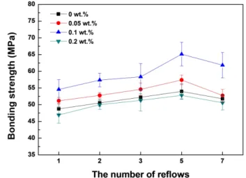
FR-4 PCB기판 및 FR-4 컴포넌트를 Sn58%Bi 복합솔더 로 접합한 시편의 접합강도를 전단시험으로 측정한 결과 는 Fig. 5에 나타내었다. Fig. 5에서 나타내는 것처럼 복 합솔더 접합부의 접합강도는 Sn-MWCNT를 0 wt.% 첨가 하였을 때 54 MPa로부터 0.1 wt.%에서는 65 MPa까지 증
가하였다. 이때 복합솔더 접합부의 접합강도가 향상되는 강화 메커니즘은 크게 2가지 현상으로 설명할 수 있다.
첫째로 Sn-MWCNT가 결정립을 미세화시키고, 증가한 결 정립계(grain boundary) 숫자가 전위(dislocation)의 이동을 방해하는, Hall-Petch 상관관계식으로 설명할 수 있다.28) 두번째로 Sn-MWCNT가 복합솔더 내부에서 pinning point 로 작용하여 전위의 이동을 방해하는 분산강화 (dispersion hardening) 메커니즘으로 인하여 기계적인 강도가 향상 된다.29)
그러나, Sn-MWCNT가 0.2 wt.% 이상일 때 다른 복합 솔더에 비해 낮은 접합강도를 나타내는 것은 과도한 Sn- MWCNT 함량으로 인해 aggregation이 발생하거나, 표면 적의 증가로 인하여 복합솔더 내부에 Fig. 7(d)와 같은 기 공(void) 량의 증가 때문으로 사료된다. 또한, 리플로우 횟 수가 5회가 될 때까지 접합강도는 증가하고 7회의 리플 로우 후의 복합솔더 접합부는 과도한 IMC의 성장으로 인 Fig. 3. IMC thickness in Sn58%Bi composite solder joints with
contents of Sn-MWCNT particle after reflow process from 1 to 7 times.
Fig. 4. SEM micrographs shows microstructures of Sn58%Bi composite solder joints with contents of Sn-MWCNT particles; (a) 0 wt.%
(b) 0.1 wt.%.
Fig. 5. Bonding strength of Sn58%Bi composite solder joints with contents of Sn-MWCNT particles and numbers of reflows.
해 오히려 접합강도가 감소하였다.30)
접합강도를 측정한 후 복합솔더 접합부의 전단시험 시 얻어지는 F-x 그래프로부터 파단이 발생하는 파괴에너지 (fracture energy)를 계산하여 Fig. 6에 나타내었다. F-x 그 래프에서 알 수 있듯이 파단이 발생하기까지 필요한 변 위(displacement to failure)는 0 wt.%에서는 895 µm, 0.1 wt.%일 때 1,209 µm로 Sn-MWCNT의 첨가에 의해 약 35% 증가하였다. 또한 파괴에너지는 접합강도와 마찬가 지로 리플로우 횟수가 5회 일 때, Sn-WMWCNT가 0.1 wt.% 첨가된 복합솔더에서 가장 높은 값인 262 mJ를 나
타내었다. 그러나 Sn-MWCNT가 0.2 wt.% 이상 첨가되었 을 때 다른 복합솔더에 비해 낮은 파괴에너지가 나타나 는 것은 MWCNT의 aggregation과 기공으로 인하여 전단 시험 시 크랙(crack)이 촉진되었기 때문이다.
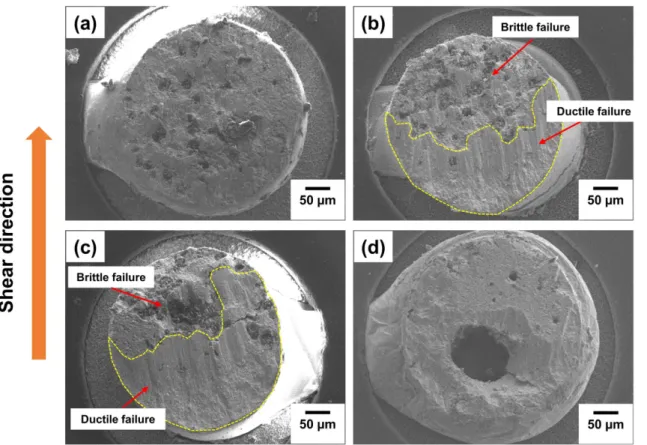
Fig. 7에 전단시험 후 파단면으로 파괴모드(failure mode) 를 나타내었다. Fig. 7에서 알 수 있듯이 Sn-MWCNT를 첨가하지 않은 Sn58%Bi 솔더 접합부에서는 솔더합금 내 부에서 취성파괴(brittle failure)가 발생하였고, Sn-MWCNT 가 첨가된 Sn58%Bi 복합솔더 접합부 일부 영역에서는 연 성파괴(ductile failure)가 발생하였다. 그러나, Fig. 8과 같 Fig. 6. (a) F-X (Force-Displacement to failure) curve after 5 times reflow, and (b) fracture energy of Sn58%Bi composite solder joints
with contents of Sn-MWCNT particles and numbers of reflows.
Fig. 7. Fracture surfaces of Sn58%Bi composite solder joints with content of Sn-MWCNT particles; (a) 0 wt.%, (b) 0.05 wt.%, (c) 0.1 wt.%, (d) 0.2 wt.%.
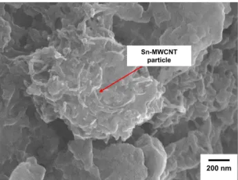
이 Sn-MWCNT가 0.2 wt.% 이상인 Sn58%Bi 복합솔더 접합부의 파단면에서 MWCNT의 aggregation 및 void가 주로 관찰되었으며, 다른 복합솔더 접합부에 비해 낮은 접합강도 및 파괴에너지를 나타내었다. 따라서, Sn- MWCNT가 0.1 wt.% 이하일 때 크랙의 전파를 방해하여 Sn58%Bi 복합솔더 접합부의 연성(ductility)을 향상시켰 음을 확인하였다.
4. 결 론
본 연구에서는 OSP처리된 FR-4 PCB기판 및 FR-4 컴 포넌트를 Sn-MWCNT를 첨가한 Sn58%Bi 복합솔더로 접 합한 뒤 접합부의 미세조직 관찰하고, 접합강도를 평가 하였다. 리플로우 횟수를 1회에서 7회까지 진행하면서 복 합솔더 접합부의 접합강도와 파단에너지를 구하고, 파괴 모드를 분석하여 아래와 같은 결론을 얻었다.
1) 리플로우 공정 이후에 솔더접합 계면에서 scallop 타 입의 Cu6Sn5 IMC가 생성되었고, 리플로우 횟수가 7회까 지 증가할 때 IMC 층은 0.45 µm에서 1.93 µm까지 증가 하였다.
2) Sn-MWCNT는 Sn rich 상에 주로 존재하여 Sn58%Bi 복합솔더의 결정립을 미세화시켰고, 접합강도 및 파괴에 너지는 각각 65 MPa, 262 mJ까지 증가하였다. 그러나, Sn- MWCNT를 0.2 wt.% 이상 첨가한 복합솔더의 접합강도 와 파괴에너지는 MWCNT의 aggregation과 void의 증가 로 인하여 각 각 53 MPa, 235 mJ를 나타내었다.
3) 리플로우 5회 실시 후 Sn-MWCNT가 0.1 wt.%인 복 합솔더 접합부의 접합강도 및 파괴에너지는 각 각 65 MPa, 262 mJ이지만 7회 리플로우 에서는 과도한 IMC의 성장으로 인하여 62 MPa, 249 mJ로 감소하였다.
4) Sn-MWCNT가 첨가되지 않은 Sn58%Bi 솔더 접합부 에서는 취성파괴가 주로 발생하고, 복합솔더의 파단면에 서는 일부 영역에서 연성파괴가 관찰되었다.
Solder Alloys with Rare Earth Element Additions”, Materials Science and Engineering: R: Reports, 44(1), 1 (2004).
5. R. A. Islam, Y. Chan, W. Jillek, and S. Islam, “Comparative Study of Wetting Behavior and Mechanical Properties (micro- hardness) of Sn–Zn and Sn–Pb Solders”, Microelectronics Journal, 37(8), 705 (2006).
6. W. R. Osório, L. C. Peixoto, L. R. Garcia, N. Mangelinck- Noël, and A. Garcia, “Microstructure and Mechanical Prop- erties of Sn–Bi, Sn–Ag and Sn–Zn Lead-free Solder Alloys”, Journal of Alloys and Compounds, 572, 97 (2013).
7. J.-W. Yoon and S.-B. Jung, “Effect of Surface Finish on Inter- facial Reactions of Cu/Sn–Ag–Cu/Cu (ENIG) Sandwich Sol- der Joints”, Journal of alloys and compounds, 448(1-2), 177 (2008).
8. W. Tomlinson and I. Collier, “The Mechanical Properties and Microstructures of Copper and Brass Joints Soldered with Eutectic Tin-bismuth Solder”, Journal of Materials Science, 22(5), 1835 (1987).
9. L. Shen, Z. Y. Tan, and Z. Chen, “Nanoindentation Study on the Creep Resistance of SnBi Solder Alloy with Reactive Nano-metallic Fillers”, Materials Science and Engineering: A, 561, 232 (2013).
10. D. Lin, G. Wang, T. Srivatsan, M. Al-Hajri, and M. Petraroli,
“Influence of Titanium Dioxide Nanopowder Addition on Microstructural Development and Hardness of Tin–lead Sol- der”, Materials Letters, 57(21), 3193 (2003).
11. T. Hu, Y. Li, Y.-C. Chan, and F. Wu, “Effect of Nano Al2O3 Particles Doping on Electromigration and Mechanical Prop- erties of Sn–58Bi Solder Joints”, Microelectronics Reliability, 55(8), 1226 (2015).
12. L. Zhang, W. Tao, J. Liu, Y. Zhang, Z. Cheng, C. Andersson, Y. Gao, and Q. Zhai, “Manufacture, Microstructure and Microhardness Analysis of Sn-Bi Lead-free Solder Rein- forced with Sn-Ag-Cu Nano-particles”, Proc. International Conference on Electronic Packaging Technology & High Density Packaging, Shanghai, China, 1, IEEE (2008).
13. S. Demoustier, E. Minoux, M. Le Baillif, M. Charles, and A.
Ziaei, “Review of Two Microwave Applications of Carbon Nanotubes: Nano-antennas and Nano-switches”, Comptes Rendus Physique, 9(1), 53 (2008).
14. L. Yang, H. Liu, Y. Zhang, and H. Yu, “Study on the Reli- ability of Carbon Nanotube-reinforced Sn-58Bi Lead-free Solder Joints”, Journal of Materials Engineering and Perfor- mance, 26(12), 6028 (2017).
15. S. Iijima, “Synthesis of Carbon Nanotubes”, Nature, 354 (6348), 56 (1991).
Fig. 8. SEM micrograph shows Sn-MWCNT particles tangled at fracture surface.
16. S. Nai, J. Wei, and M. Gupta, “Lead-free Solder Reinforced with Multiwalled Carbon Nanotubes”, Journal of electronic materials, 35(7), 1518 (2006).
17. H. Peng, X.-c. LÜ, T.-S. Lin, H.-X. Li, A. Jing, M. Xin, J.- C. Feng, Y. Zhang, L. Qi, and Y.-Y. Qian, “Improvement of Mechanical Properties of Sn–58Bi Alloy with Multi-walled Carbon Nanotubes”, Transactions of Nonferrous Metals Soci- ety of China, 22, s692 (2012).
18. H. Sun, Y. Chan, and F. Wu, “The Impact of Reflow Solder- ing Induced Dopant Redistribution on the Mechanical Prop- erties of CNTs Doped Sn58Bi Solder Joints”, Journal of Materials Science: Materials in Electronics, 26(7), 5318 (2015).
19. H. Sun, X. Hu, Y. Chan, and F. Wu, “Effect of Nickel-coating Modified CNTs on the Dopant Dispersion and Performance of BGA Solder Joints”, Proc. 67th Electronic Components and Technology Conference (ECTC), 1981, IEEE (2017).
20. S. Chantaramanee, S. Wisutmethangoon, L. Sikong, and T.
Plookphol, “Development of a Lead-free Composite Solder from Sn–Ag–Cu and Ag-coated Carbon Nanotubes”, Journal of Materials Science: Materials in Electronics, 24(10), 3707 (2013).
21. C.-J. Lee, K. D. Min, B.-U. Hwang, J.-H. Kim, and S.-B.
Jung, “The Effect of pH on Synthesizing Ni-decorated MWCNTs and its Application for Sn-58Bi Solder”, Current Applied Physics, 19(11), 1182 (2019).
22. C.-J. Lee, K. D. Min, H. J. Park, J.-H. Kim, and S.-B. Jung,
“Effect of Sn-Decorated MWCNTs on the Mechanical Reli- ability of Sn–58Bi Solder”, Electronic Materials Letters, 15(6), 693 (2019).
23. C.-J. Lee, H. Jeong, K.-H. Jung, K. D. Min, and S.-B. Jung,
“Thermal and Mechanical Property of FCLED Package Com- ponent Interconnected with Sn–MWCNT Composite Solder”, Journal of Materials Science: Materials in Electronics, 30, 12869 (2019).
24. H. Ohtani and K. Ishida, “A Thermodynamic Study of the Phase Equilibria in the Bi-Sn-Sb System”, Journal of Elec- tronic Materials, 23(8), 747 (1994).
25. C. Zhang, S.-d. Liu, G.-t. Qian, Z. Jian, and X. Feng, “Effect of Sb Content on Properties of Sn—Bi solders”, Transactions of Nonferrous Metals Society of China, 24(1), 184 (2014).
26. F. Wang, L. Zhou, Z. Zhang, J. Wang, X. Wang, and M. Wu,
“Effect of Sn-Ag-Cu on the Improvement of Electromigration Behavior in Sn-58Bi Solder Joint”, Journal of Electronic Materials, 46(10), 6204 (2017).
27. P. Liu, P. Yao, and J. Liu, “Effects of Multiple Reflows on Interfacial Reaction and Shear Strength of SnAgCu and SnPb Solder Joints with Different PCB Surface Finishes”, Journal of Alloys and Compounds, 470(1-2), 188 (2009).
28. K. M. Kumar, V. Kripesh, and A. A. Tay, “Influence of Sin- gle-wall Carbon Nanotube Addition on the Microstructural and Tensile Properties of Sn–Pb Solder Alloy”, Journal of Alloys and Compounds, 455(1-2), 148 (2008).
29. L. Zhang and K.-N. Tu, “Structure and Properties of lead-free Solders Bearing Micro and Nano particles”, Materials Science and Engineering: R: Reports, 82, 1 (2014).
30. H.-J. Park, C.-J. Lee, K. D. Min, and S.-B. Jung, “Micro- structures and Mechanical Properties of the Sn58wt.% Bi Composite Solders with Sn Decorated MWCNT Particles”, Journal of Electronic Materials, 48(3), 1746 (2019).