Numerical Investigation of Effects of Tip Clearance Height on Fan Performance and Tip Clearance Flow in an Axial Fan of the
Cooling Tower
냉각탑용 축류팬의 팁 간격이 팬 성능 및 틈새 유동에 미치는 영향에 관한 수치해석적 연구
KeonJe Oh 오 건 제
(접수일 : 2011년 07월 08일, 수정일 : 2011년 09월 09일, 채택확정:2011년 09월 09일)
Key Words:냉각탑용 팬(Cooling Tower Fan), 팁 간격(Tip Clearance Height), 성능(Performance), 누설유동 (Leakage Flow), 전산유체역학(CFD)
Abstract:팁 간격의 크기가 냉각탑용 축류팬의 성능과 누설 유동에 미치는 영향을 조사하기 위해서 서로 다 른 2가지 팁 간격을 가진 경우에 대해서 점성유동을 해석하였다. 케이싱 내에서 작동하는 축류팬 주위의 유 동을 연속방정식, Navier-Stokes 방정식 등을 지배방정식으로 사용하여 수치해석 하였다. 난류유동에 나타나
는 레이놀즈 응력은 난류모델을 사용하여 계산하였다. 전체적으로 H형 격자계를 사용하였으며, 팁 주
위의 유동을 해석하기 위해서 팁 영역 주위에 부분적으로 조밀한 격자를 두었다. 팁 간격이 증가하면 누설 유동의 증가로 인한 유동 손실의 증가로 전압상승과 수력효율이 감소하였다. 팬 직경에 대한 팁 간격이 0.4%에서 1.0%로 증가하면 전압상승 값이 약 10% 정도 감소하였으며, 수력효율은 약 3% 정도 감소하였다.
팁 간격이 팁 근처 날개 주위의 압력에 미치는 영향을 보면, 팁 간격이 증가하여 누설 유동이 증가하면 흡 입면과 압력면의 압력차가 전연 부근에서 감소함을 알 수 있었다. 누설 와류의 중심은 코드를 따라서 흡입 면으로 부터 떨어져 나가면서 형성됨을 알 수 있었다. 누설 와류의 위치를 보면 팁 간격이 증가하면 와류 중심의 위치가 흡입면 쪽으로 이동하고, 흡입면에서 떨어진 거리도 날개 후반부에서 증가 폭이 커지는 포물 선 형태로 증가함을 알 수 있었다.
오건제(교신저자) : 경남대학교 기계자동화공학부 E-mail : [email protected], Tel : 055-249-2616
1. 서 론
Cooling towers are heat removal devices and axial flow fans are widely used to force the air into the tower. The flow in the tip clearance region between the rotor of the fan and the casing is quite complex and presents interesting flow features. The interaction between the tip leakage flow and the passage flow causes the rolling-up of the tip leakage vortex and flow separations on the casing. Characteristics of the tip flow field are highly sensitive to variations in tip clearance height. Most of previous studies concerning the tip
clearance flow have been focused on the axial compressors
1-5). Little research effort has been made to understand the tip clearance flow field for the axial fans. Zhu et al.
(6)measured and calculated the flow field in the tip clearance region of an axial ventilation fan with various tip clearance heights. However, they did not show the detailed behavior of the tip clearance flow in the blade passage. The cooling tower fan for the present study is very large and has a high Reynolds number. It is difficult to conduct measurements of the flow field in the tip clearance region for the fan with a high Reynolds number.
Numerical simulation technique is a useful tool to
describe the tip flow field of the cooling tower fan.
The purpose of the present study is to investigate effects of the tip clearance height on the structures of the tip clearance flow field in an axial fan of the cooling tower. Viscous flow calculations are performed for the fan flow field including the tip clearance flow using the Navier-Stokes equations and the turbulence model. The turbulence model can give good results for the turbulent flows with high Reynolds number like the present flow model. Calculation results are obtained at two tip clearance heights.
The secondary flows in various cross-flow planes at the tip, the static pressure distributions on the blade surface near the tip and the trajectory of the tip vortex core in the blade passage are examined to understand the flow structure and the effects of the clearance height on the tip flow field.
2. Axial fan model
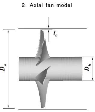
Fig. 1 Ducted fan model
The present fan model is a ducted fan as shown in Fig. 1. The fan model of interest is a large axial flow fan which is currently used in the cooling tower. The fan has six blades, the diameter of the fan D
is 4.27 m, and the hub ratio(=D
hD
) is 0.3. The design flow rate Q is 10,000 m
min and the rotational speed of the fan is 250 rpm. The flow coefficient
A⋅V Q
is
0.229 where V
tis the tip speed and A
D
D
h
is the inlet area. The blade section has NACA 4409 airfoil geometry. The chord length at the hub is 1,048 mm and the chord length at the tip is 524 mm. The blade stagger angles at the tip and the hub are given 70° and 38.6°, respectively. The Reynolds number, based on the tip speed and the diameter of the fan, is 1.602×10
7. The normalized tip clearance heights to the fan diameter t
cD
are chosen as 0.4% and 1.0%. These two values correspond to a small and a large tip clearance gap, respectively, of the ducted axial fan.
3. Governing equations
The govering equations are the continuity and the Reynolds-averaged Navier-Stokes equations.
The Reynolds stresses are modeled using the turbulence model. The governing equations in the rotating cylindrical coordinate can be written as
x
U r
r
rV r
W
(1) where ,
, and S
denote the flow variables, diffusion coefficients, and source terms, respectively
(7).
4. Computational procedure
Fig. 2 Grid configuration on the hub shaft and the
blade
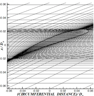
Fig. 3 A close view of the computational grid at the tip on the constant radius surface
The governing equations are solved using the Navier-Stokes code which was developed and validated for the simulation of turbulent flows in an axial fan model by author et al.
7-8). The code uses hybrid numerical scheme and the SIMPLE algorithm based on the finite volume approach.
The H-type computational grids are generated in the calculation domain of one blade passage between the hub and the casing. The grid consists of 93 and 72 in the axial and circumferential(blade to blade) directions. Particularly, 20 grid points are distributed in the circumferential direction on the tip surface. In the radial direction, 65 grid points are used in the region between the hub and the tip. In the tip clearance region between the tip and the casing, 12 and 30 grid points are allocated for the case of t
cD
=0.4% and 1.0%, respectively.
Fine grid spacings are used near the leadings, trailing edges and wall surfaces. The grid configuration on the hub shaft and the blade is shown in Fig.2. A close view of the computational grid at the tip on the constant radius surface is shown in Fig.3.
The inlet and outlet boundary planes are placed 0.3 fan diameter upstream and 0.5 fan diameter downstream of the fan. A constant volume flow rate is specified over the inlet and outlet planes.
The wall function is used for boundary conditions on the wall surfaces. Periodic boundary conditions are imposed in the circumferential direction.
5. Result and discussion
Table 1 Performance data for the axial fan model Tip clearance height [%] 0.4 1.0
Flow rate [m
3/min] 10,000 10,000
Flow coefficient 0.229 0.229
Total pressure rise [Pa] 255.18 232.82 Pressure coefficient 0.135 0.124 Hydraulic efficiency [%] 67.56 64.63
At first, calculated performance data for the two clearance heights are presented in Table 1. The pressure coefficient is defined by ⋅V
t⋅P
twhere P
tis the total pressure rise, is the fluid density, and V
tis the tip speed. Table 1 shows that the total pressure rise is seen to be substantially decreased as the clearance height is increased. Calculations show a loss of around 10%
in the total pressure rise as the clearance height is increased from 0.4% to 1.0%. With increasing tip clearance height, the increased tip leakage flow induces a more flow loss in the tip clearance region and the hydraulic efficiency are decreased.
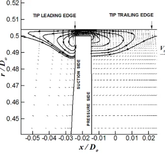
Fig. 4 Cross sections at the tip and other notations
Fig. 5(a) Projected velocity vectors and stream-traces in the cross section a a′ at
c
xl
tip for t
cD
Fig.4 shows definitions of the cross section at the tip and other notations to be used for the display of the calculation results. The section a a′ is parallel to the axial direction. The section b b′ is perpendicular to the camber line on the tip surface. The distance y in the cross section b b′ is measured from the wall. The axial chord c
xis measured from the tip leading edge.
Fig. 5(b) Projected velocity vectors and stream-traces in the cross section a a′ at
c
xl
tip for t
cD
Projected velocity vectors and stream-traces of the tip leakage flow in the cross section a a′
at c
xl
tip are shown in Fig. 5. The velocity vectors in the relative coordinate to the moving blade are projected into the cross section a a′.
The tip leakage flow meets with the incoming flow and causes the severe interaction, resulting in a flow separation region on the casing. This flow region acts like a blockage to the incoming passage flow to the blade. The size of the region becomes larger in the larger clearance case which is due to the more entrainment of the leakage flow. It is observed that the flow moves upward on the pressure side to enter the gap and moves downward on the suction side mixing with the incoming flow.
Static pressure distributions on the blade surface at ⋅rD
are shown in. Fig. 6. The static pressure is non-dimensionalized by the tip speed and the fluid density. The pressure difference between the pressure and the suction side near the leading edge is reduced in the larger clearance case. The pressure difference across the tip near the leading edge is decreased by the blockage effect of the leakage flow. Therefore, when the clearance height is increased, the tip leakage flow region is extended as shown in Fig.
5 and the pressure difference is further reduced by
Fig. 6 Static pressure distributions on the blade
surface at ⋅rD
the larger blockage effect. It can be also found that the location of the minimum pressure on the suction side moves downstream in the larger clearance case. The location of minimum pressure is linked to the detachment of the tip leakage vortex.
Fig. 7(a) Projected velocity vectors and stream-traces in the cross section b b′ at c
xl
tip for
t
cD
Fig. 7(b) Projected velocity vectors and stream-traces in the cross section b b′ at
c
xl
tip for t
cD
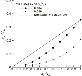
Fig. 8 Trajectories of the tip leakage vortex in the blade passage
Projected velocity vectors and stream- traces of the secondary flow in the cross section b b′ at c
xl
tip are shown in Fig.7. Fig. 7 shows that the tip leakage flow exits the gap like a jet flow and rolls up into a discrete vortex. The tip vortex core is more detached from the suction side wall when the tip clearance height is decreased from 1.0% to 0.4%. This indicates that the trajectory of the vortex depends on the clearance height.
Fig. 8 shows the trajectories of the tip leakage vortex in the blade passage. The distance of the vortex center y
cis measured from the suction side of the blade in the b b′ section. Present results are compared with the following similarity solution of the idealized model by Chen et al.
(1).
x x
Ly
c ⋅
cos
⋅
tan
tan
m id span
(2)
where
x−xLis the axial distance from the leading edge at the tip,
β1is the inlet flow angle,
β2
is the outlet flow angle,
βmis the mean flow
angle, and
σis the solidity. The idealized model
has been derived by a similarity analysis in the
transverse section based on an inviscid slender
body approach. The model assumes that the
clearance height and the transverse plane velocities
are very small, and the pressure difference across the blade does not vary in the span. In the idealized model, the onset of vortex roll-up occurs at the leading edge and the vortex is detached from the suction side at a constant rate. However, present results show that the initial vortex appears further downstream and that the vortex remains close to the wall in the forepart of the chord before it is rapidly detached from the wall. Also, it is found that the detachment moves further downstream in the larger clearance case. Similar feature of the tip leakage vortex can be observed in the experimental study by Inoue and Kuroumaru
(3)for an axial compressor rotor. These discrepancies in the trajectory are due to the fact that the formation and the detachment of the vortex are influenced by the pressure on the blade surface near the tip which is given in Fig. 4. The reduced pressure difference near the leading edge by the blockage effect of the leakage flow moves the onset of the vortex downstream. The detachment of the vortex is delayed in the larger clearance case as the location of minimum pressure on the suction side moves further downstream in the chord-wise direction.
6. Conclusions
In this paper, tip clearance flows in an axial fan of the cooling tower are simulated at two tip clearance heights. From the calculation results, the following conclusions can be drawn:
1. Calculated performance data show a loss of around 10% in the total pressure rise when the clearance height is increased from 0.4% to 1.0%.
2. A flow separation region can be seen on the casing near the tip which is due to the interaction of the leakage flow with the incoming passage flow. This region acts like a blockage to the incoming passage flow. The size of the region becomes large as the clearance height is increased.
3. The pressure difference between the pressure and the suction side near the tip is further reduced
in the larger clearance case by the larger blockage effect of the leakage flow. The location of minimum pressure on the suction side moves downstream when the clearance height is increased.
4. In the present calculations, the initial vortex appears further downstream, whereas in the idealized model by Chen et al.
(1), the vortex is generated at the leading edge. The detachment of the vortex is further delayed at the larger clearance as the location of minimum pressure on the suction side moves further downstream in the chord-wise direction.
Acknowledgement
This work was supported by Kyungnam University Foundation Grant, 2010.
Reference