Vol. 25, No. 1 (2015)
48
Rapid Synthesis and Consolidation of Nanostructured Ti-TiC Composites from TiH
2and CNT by Pulsed Current Activated Heating
Na-Ra Park and In-Jin Shon
†Division of Advanced Materials Engineering, the Research Center of Hydrogen and Fuel Cell, Chonbuk National University, 664-14 Deokjin-dong 1-ga, Deokjin-gu, Jeonju, Jeonbuk 561-756, Korea
(Received November 1, 2014 : Received in revised form December 24, 2014 : Accepted December 25, 2014)
Abstract
TiH2 nanopowder was made by high energy ball milling. The milled TiH2 and CNT powders were then simultaneously synthesized and consolidated using pulsed current activated sintering (PCAS) within one minute under an applied pressure of 80 MPa. The milling did not induce any reaction between the constituent powders. Meanwhile, PCAS of the TiH2-CNT mixture produced a Ti-TiC composite according to the reaction (0.92TiH2+ 0.08CNT→ 0.84Ti + 0.08TiC + 0.92H2, 0.84TiH2+ 0.16CNT→ 0.68Ti + 0.16TiC + 0.84H2). Highly dense nanocrystalline Ti-TiC composites with a relative density of up to 99.7 % were obtained. The hardness and fracture toughness of the dense Ti-8 mole% TiC and Ti-16 mole%TiC produced by PCAS were also investigated. The hardness of the Ti-8 mole% TiC and Ti-16 mole% TiC composites was higher than that of Ti. The hardness value of the Ti-16 mole% TiC composite was higher than that of the Ti-8 mole% TiC composite without a decrease in fracture toughness.
Key words
rapid sintering, composit, nanomaterial, mechanical properties, Ti-TiC.1. Introduction
Metal-ceramic composites have been developed to find for the optimum combination of low density, high oxi- dation resistance and high hardness of ceramic and metal toughness. They are recommended as candidates for bio- materials, aerospace, automotive and defense applications.
Ti has a density of 4.506 g cm
−3, a Young’s modulus of 116 GPa, a biocompatibility and a good fracture toughness.
The attractive properties of titanium carbide is high hard- ness, low density, relatively high thermal and electrical conductivities. TiC is also very stable, with a melting temperature of 2727 K, and does not undergo phase transformations. Hence, a microstructure consisting of Ti and TiC may be able to satisfy the mechanical property requirements of structural materials.
Nanocrystalline materials have been extensively studied in order to produce advanced materials that have im- proved physical and mechanical properties,
1,2)such high strength and hardness as well as excellent ductility and toughness.
3,4)Recently, nanocrystalline powders have been developed using thermochemical and thermomechanical
processes such as the spray conversion process(SCP), co- precipitation, and high-energy milling.
5-7)The sintering temperature of high-energy mechanically milled powder is lower than that of unmilled powder due to the increased reactivity, internal and surface energies, and surface area of the milled powder, all of which contribute to its mechanical activation.
8-10)However, the grain size of sintered materials is much larger than that of pre-sintered powders due to the rapid grain growth during conventional sintering. Therefore, even though the initial particle size can be less than 100 nm, the grain size rapidly increases up to 2 μm or larger during conventional sintering.
11)Therefore, one of the keys to the commercial success of nanostructured materials is to control the grain growth during sintering. In this regard, PCAS has been shown to be effective for sintering nanostructured materials over very short times(within 1 minute).
12-14)This paper reports on the simultaneously rapid synthesis and consolidation of dense nanostructured Ti-TiC com- posite starting with high-energy ball-milled TiH
2and CNT nanopowders using PCAS. The mechanical properties
†Corresponding author
E-Mail : [email protected] (I.-J. Shon, Chonbuk Nat'l Univ.)
©Materials Research Society of Korea, All rights reserved.
This is an Open-Access article distributed under the terms of the Creative Commons Attribution Non-Commercial License (http://creative- commons.org/licenses/by-nc/3.0) which permits unrestricted non-commercial use, distribution, and reproduction in any medium, provided the original work is properly cited.
Rapid Consolidation of Nanostructured Ti-TiC Composites from TiH2 and CNT by Pulsed Current Heating 49
and grain sizes of the resulting nanostructured Ti-TiC composite were also evaluated by Vickers hardness and FE-SEM.
2. Experimental Procedures
TiH
2(99.5 %, −200 mesh, Sejong) and CNT(Carbon Nanotechnolgies Incorporated) powders were used as raw materials. TiH
2and CNT powders were mixed in a high energy ball mill. For high-energy ball milling, a Pulverisette-5 planetary mill was used at 250 rpm for 10 h. Tungsten carbide balls(9 mm in diameter) were used for milling in a sealed cylindrical stainless steel vial under argon atmosphere. The weight ratio of ball-to-powder was 30:1. After the milling process, the grain sizes of the mixed TiH
2and CNT powders were calculated by Suryanarayana and Norton’s formula
15):
B
r(B
crystalline+ B
strain) cosθ = k λ / L + ηsinθ (1) where B
ris the full width at half-maximum(FWHM) of the diffraction peak after instrumental correction, B
crystallineand B
strainare FWHM caused by the small grain size and internal stress, respectively, k is a constant(with a value of 0.9), λ is the wavelength of the X-ray radiation; L and η are the grain size and internal strain, respectively; and θ is the Bragg angle. The parameters B and B
rfollow Cauchy’s form with the relationship: B = B
r+ B
s, where B and B
sare the FWHM of the broadened Bragg peak and the standard sample’s Bragg peaks, respectively.
After the milling processes, the milled powders were placed in a graphite die(outside diameter, 35 mm; inside diameter, 10 mm; height, 40 mm) and were then intro- duced into the pulsed current activated sintering system (Eltek, South Korea), shown schematically in Ref.
12-14)The four major stages in the sintering process were as follows: Stage 1 involved the creation of a vacuum in the system. During Stage 2, a uniaxial pressure of 80 MPa was applied. During Stage 3, a pulsed current(on time;
20 μs, off time; 10 μs) flowed into the system and was maintained at 1150
oC with a heating rate of 1200
oC/min.
The system was then turned off without a holding time.
A pyrometer focused on the surface of the graphite die measured the temperature during PCAS. Finally, during Stage 4, the sample was cooled to room temperature. The process was carried out under a vacuum of 5.33 Pa.
The relative densities of the sintered sample were mea- sured by the Archimedes method. Microstructural infor- mation was obtained from the Ti-TiC composites which were polished. Compositional and microstructural analyses of the products were performed through X-ray diffrac- tion(XRD), and scanning electron microscopy(SEM) with energy dispersive X-ray analysis(EDAX). Vickers hardness
was measured by performing indentations at load of 10 kg and a dwell time of 15 s on the sintered samples.
3. Results and Discussion
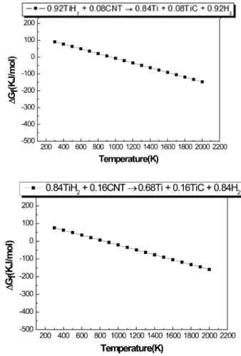
The interaction between TiH
2and CNT, i.e.,
0.92TiH
2+ 0.08CNT → 0.84Ti + 0.08TiC + 0.92H
2(2) 0.84TiH
2+ 0.16CNT → 0.68Ti + 0.16TiC + 0.84H
2(3) are thermodynamically feasible above 800K as shown in Fig. 1.
Fig. 2 indicates X-ray diffraction patterns of high energy ball milled powders. Only TiH
2peaks were identified after milling. This indicates that reaction (2) and (3) did not occur during the high energy ball milling method.
However, the full width at half-maximum(FWHM) of the diffraction peak in Fig. 2(a) and (b) are broad due to the refinement of powders and strains. Therefore, powder milled using the high energy ball milling method was smaller than that of raw powder. The grain size of TiH
2calculated using Suryanarayana and Grant Norton’s
Fig. 1. Temperature dependence of the Gibbs free energy variation by interaction of TiH2 with CNT.
formula was 22 nm.
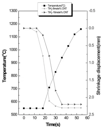
The shrinkage displacement-time(temperature) curve pro- vides a useful information on the consolidation behavior.
Fig. 3 shows the shrinkage record of TiH
2-8 mole%
CNT, and TiH
2-16 mole% CNT compacts. In all cases, the shrinkage displacements are nearly constant up to 550
oC and then abruptly increase above the temperature.
Afterwards, they contract almost linearly above tem- perature of 950
oC at which the consolidation terminates.
The shrinkage curve suggests that the consolidation terminates in one minute.
These powders were rapidly sintered under the applica- tion of high pressure(80MPa) which had a significant effect on the total driving force, F
D, as
16)F
D= γ + (P
ar/ π), (4)
where γ is the surface energy, P
ais the applied pressure, and r is the radius of the particle. The effect of pressure on the densification of TiO
2during high- frequency induction heated sintering was investigated by Shon et al.
17)A significant increase in the relative density was observed as the pressure increased from about 60 to 100MPa during sintering at 800
oC. Secondly, the role of
the current(resistive or inductive) in sintering and or synthesis has been the focus of several attempts aimed at providing an explanation for the observed enhancement of sintering and the improved characteristics of the products. The role played by the current has been in- terpreted in various ways, the effect being explained in terms of the fast heating rate due to Joule heating, the presence of plasma in pores separating powder particles, and the intrinsic contribution of the current to mass transport.
18-21)Thirdly, raw powders were very fine and many defect was introduced by high-energy ball milling.
So, The powders were activated, and contact points for diffusion route increased. The sintering temperature of high-energy mechanically milled powder is lower than that of unmilled powder due to the increased reactivity, internal and surface energies, and surface area of the milled powder, which contribute to its so-called mechanical activation.
22-24)Fig. 4 shows XRD patterns of the high-energy ball milled powder heated to 1150
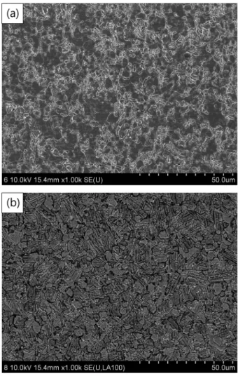
oC in which only Ti and TiC peaks are detected. The average grain sizes of Ti and TiC in the composites sintered from high energy ball milled powders using Suryanarayana and Grant Norton’s formula are 132 nm, 65 nm and 78 nm, 24 nm which were obtained from X-ray data in Fig. 4 using Sur- yanarayana and Norton’s formula. Fig. 5 shows the SEM
Fig. 3. Variations of temperature and shrinkage displacement with heating time during the sintering of TiH2-8 mole%CNT, and TiH2- 16 mole% CNT by PCAS.Fig. 2. XRD patterns of mechanically milled powders: (a) TiH2-8 mole%CNT, (b) TiH2-16 mole%CNT.
Rapid Consolidation of Nanostructured Ti-TiC Composites from TiH2 and CNT by Pulsed Current Heating 51
images of Ti-8 mole% TiC, and Ti-16 mole% TiC samples heated to 1150
oC. Nearly full dense Ti-8 mole% TiC, and Ti-16 mole% TiC composites were observed in Fig.
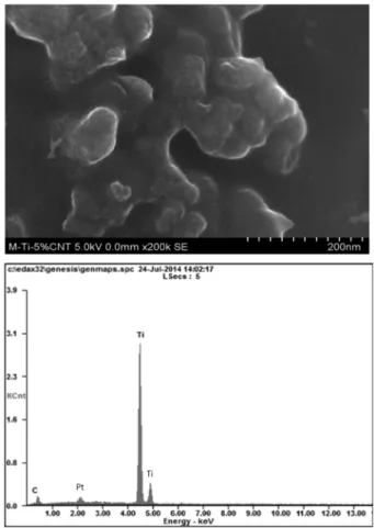
5(a) and (b). The corresponding relative densities were 99.6 and 99.7 %, respectively. FE-SEM image and EDS of Ti-16 mole% TiC composite was shown in Fig. 6. It is also obvious that the microstructure consists of nanograins in Fig. 6. And in EDS, Ti, C and Pt peaks were detected.
Pt comes from surface coating to observe microstructure clearly. And there are no other peaks, such as Fe or W, which can possibly happen during the milling process.
Vickers hardness measurements were made on polished sections of the Ti-8 mole% TiC and TiC-16 mole% TiC composites composite using a 10 kg
fload and a 15 s dwell time. The calculated hardness value of Ti-8 mole%
TiC and TiC-16 mole.% TiC composites sintered at 1150
o
C from high energy ball milled powders were 888 and 952 kg/mm
2, respectively. These values represent an average of five measurements. Indentations with large enough loads produced median cracks around the indentation. The length of these cracks permits an estimation of the fracture toughness of the material. From the length of these cracks, fracture toughness values can be determined using the equation by Anstis et al.
25)K
IC= 0.016(E/H)
1/2· P/C
3/2(5) where E is Young’s modulus, H the indentation hardness, P the indentation load, and C the trace length of the crack measured from the center of the indentation.
The modulus was estimated by the rule of mixtures for the 0.09 and 0.18 volume fraction of TiC and the 0.91and 0.82 volume fraction of Ti in Ti-8 mole% TiC and TiC- 16 mole.% TiC composites, using E(TiC) = 517.9 GPa
26)and E(Ti) = 116 GPa.
27)As in the case of hardness values, the toughness values were derived from the average of five measurements. The toughness values of Ti-8 mole%
TiC and Ti-16 mole% TiC composites obtained from high energy ball milled powders are 7.5 and 7.3 MPa·m
1/2, respectively.
Kim et al.
28)studied on sintering of nanostructured Ti from miiled TiH
2by high-frequency induction heating.
The hardness of nanostructured Ti was reported as 567 kg/mm
2. The hardness values of Ti-8 mole% TiC and Ti- 16 mole% TiC composites were higher than that of TiC due to addition of TiC hard phase as expected. Com-
Fig. 5. SEM images of Ti-TiC system : (a) Ti-8 mole% TiC and (b) Ti-16 mole% TiC.Fig. 4. XRD patterns of (a) Ti-8 mole% TiC and (b) Ti-16 mole%
TiC composites sintered from high energy ball milled powders.
paring hardness and fracture toughness of Ti-8 mole%
TiC with Ti-16 mole% TiC, hardness of TiC-16 mole%
TiC composite is higher than that of Ti-8 mole% TiC composite without decease of fracture toughness. Fig. 7 shows Vickers indentation in the Ti-8 mole% TiC and Ti- 16 mole% TiC composites sintered from high energy ball milled powders. One to three additional cracks were observed to propagate from the indentation corner. The toughness of Ti-TiC composite may be that the TiC may deter the crack propagation. Fig. 8 shows a crack pro- pagated in a deflective manner( ↑) in Ti-16 mole% TiC composite. The reason without decrease of fracture toughness of Ti-16 mole% TiC composite is believed that TiC in the composite may deter the crack propagation.
4. Conclusions
TiH
2nanopowders were made by a high energy ball milling method. Using pulsed current activated sintering, simultaneous synthesis and densification of Ti-8 mole%
TiC with Ti-16 mole% TiC composites was accomplished.
Relative densities of the sintered specimens were 99.6 % and 99.7 %, respectively. The average grain sizes of Ti and TiC in the composites sintered from high energy ball milled powders are 132 nm, 65 nm and 78 nm, 24 nm,
respectively. The calculated hardness value of Ti-8 mole%
TiC and Ti-16 mole.% TiC composites were 888, 952 kg/
mm
2and 7.5, 7.3 MPa·m
1/2, respectively. The hardness of TiC-16 mole% TiC composite is higher than that of Ti- 8 mole% TiC composite without decease of fracture
Fig. 7. Vickers hardness indentation in (a) Ti-8 mole% TiC and (b) Ti-16 mole% TiC composites.Fig. 8. Crack propagation in a Ti-16 mole% TiC composite.
Fig. 6. FE-SEM image and EDS of a Ti-16 mole% TiC composite.
Rapid Consolidation of Nanostructured Ti-TiC Composites from TiH2 and CNT by Pulsed Current Heating 53
toughness. The reason without decrease of fracture tough- ness of TiC-16 mole% TiC composite is believed that TiC in the composite may deter the crack propagation.
Acknowledgment
This research was supported by the Basic Science Re- search Program, through the National Research Foundation of Korea(NRF), funded by the Ministry of Education(No.
2012R1A1A4A01001300) and this work was supported by the Human Resources Development program(No.
20134030200330) of the Korea Institute of Energy Tech- nology Evaluation and Planning(KETEP) grant funded by the Korea government Ministry of Trade, Industry and Energy.
References
1. M. Sherif El-Eskandarany, J. Alloys Compd., 305, 225 (2000).
2. L Fu, LH Cao and YS Fan, Scripta Materialia, 44, 1061 (2001).
3. H. S. Kang, I. J. Shon, J. M. Doh and J. K. Yoon, Mater. Trans., 55(7), 1109 (2014).
4. I. J. Shon, H. S. Kang, J. M. Doh, B. J. Park and J. K.
Yoon, Mater. Trans., 53, 1539 (2012).
5. Z Fang, JW Eason, Int. J. Refractory Met. Hard Mater., 13, 297 (1995).
6. I. J. Shon, K. I. Na, J. M. Doh, H. K. Park and J. K.
Yoon, Met. Mater. Int., 19, 99 (2013).
7. S. M. Kwak, H. K. Park and I. J. Shon, Korean J. Met.
Mater., 51, 314 (2013).
8. F. Charlot, E. Gaffet, B. Zeghmati, F. Bernard, J. C.
Liepce, Mater. Sci. Eng., A262, 279 (1999).
9. G. W. Lee and I. J. Shon, Korean J. Met. Mater., 51, 95 (2013).
10. M. K. Beyer, H. Clausen-Schaumann, Chem. Rev., 105,
2921 (2005).
11. J. Jung and S. Kang, Scripta Materialia, 56, 561 (2007).
12. N. R. Park and I. J. Shon, Korean J. Met. Mater., 51, 821 (2013).
13. N. R. Park, K. I. Na, H. J. Kwon, J. W. Lim and I. J.
Shon, Korean J. Met. Mater., 51, 753 (2013).
14. I. J. Shon, S. L. Du, J. M. Doh and J. K. Yoon, Met.
Mater. Int., 19, 1041 (2013).
15. C Suryanarayana, M Grant Norton, X-ray diffraction a practical approach, p. 213, New York, Plenum Press (1998).
16. R. L. Coble, J. Appl. Phys., 41, 4798 (1970).
17. H. C. Kim, H. K Park, I. J. Shon and I. Y. Ko, J. Ceram.
Process. Res., 7, 327 (2006).
18. Z Shen, M Johnsson, Z Zhao and M Nygren, J. Am.
Ceram. Soc., 85, 1921 (2002).
19. JE Garay, U Anselmi-Tamburini, ZA Munir, SC Glade and P Asoka- Kumar, Appl. Phys. Lett., 85, 573 (2004).
20. JR Friedman, JE Garay, U Anselmi-Tamburini, ZA Munir, Intermetallics, 12, 589 (2004).
21. JE Garay, U Anselmi-Tamburini and ZA Munir, Acta Mater., 51, 4487 (2003).
22. F. Charlot, E. Gaffet, B. Zeghmati, F. Bernard and J. C.
Liepce, Mater. Sci. Eng., A262, 279 (1999).
23. I. J. Shon, S. L. Du, H. S. Kang, J. M. Doh and J. K.
Yoon, Mater. Res. Bull., 49, 584 (2014).
24. M. K. Beyer and H. Clausen-Schaumann, Chem. Rev., 105, 2921 (2005).
25. GR Anstis, P Chantikul, BR Lawn and DB Marshall, J.
Am. Ceram. Soc., 64, 533 (1981).
26. J. W. Kim and S.H. Kang, J. Alloys Compd., 528, 20 (2012).
27. http://en.wikipedia.org/wiki/Elastic properties of the elements (data page).
28. N. R. Kim, S. W. Cho, W. B. Kim and I. J. Shon, Korean J. Met. Mater., 50(1), 34 (2012).