- 195 -
Experimental Evaluation of Superconductor Flywheel Energy Storage System with Hybrid Type Active Magnetic Bearing
J. P. Lee
*,a, H. G. Kim
a, S. C. Han
ba Kyungnam College of Information & Technology, Busan, Korea
b Korea Electric Power Research Institute, Deajeon, Korea (Received 16 March 2012; revised 10April2012; accepted 11 April 2012)
하이브리드 AMB를 포함한 초전도 플라이휠 에너지 저장장치의 실험평가
이정필
*,a, 김한근
a, 한상철
bAbstract
In this paper, we designed Active Magnetic Bearing (AMB) for large scale Superconductor Flywheel Energy Storage System (SFESS) and PD controller for AMB. And we experimentally evaluated SFESS including hybrid type AMB. The radial AMB was designed to provide force slew rate that was sufficient for the unbalance disturbances at the maximum operating speed. The thrust AMB is a hybrid type where a permanent magnet carries the weight of the flywheel and an electromagnetic actuator generates the dynamic control force. We evaluated the design performance of the manufactured AMB through comparison of FEM analysis and the results of experimental force measurement. In order to obtain gains of PD controller and design a notch filter, the system identification was performed through measuring frequency response including dynamics for the AMBs, a power amp and a sensor using a sine swept test method after levitating the flywheel. Through measuring the current input of the AMBs and the orbit of a flywheel according to rotational speed, we verified excellent control performance of the AMBs with small amount current for the large scale SFESS.
Keywords : Active magnetic bearing, Superconductor flywheel energy storage system(SFESS), Notch filter, Sine swept test, PD controller
I. Introduction
In recent, many researches on an energy storage system have been done since an energy storage
system is able to cope with varying power demand, and is efficient countermeasure to improve power quality. An energy storage system can be used for an uninterruptible power supply (UPS), power quality improvement, load leveling, and storage of a distributed power source such as a solar power and a wind power. A superconductor flywheel energy
*Corresponding author. Tel : +82 51 320 1492 e-mail : [email protected]
storage system (SFESS) is more attractive than any other energy storage system because of various reasons such as rapid charge/discharge, infinite charge/discharge cycle and environmental friendliness [1, 2].
Since the SFESS with an AMB can minimize a mechanical friction loss, the energy efficiency is higher than that with a mechanical bearing such as a ball bearing. However, continuous supply of power is needed to levitate a flywheel and to control position of a flywheel shaft using an AMB. Therefore the AMB and the controller must be designed for minimizing consumption of power.
In this paper, we designed and manufactured the AMBs which were composed of a radial bearing and a hybrid thrust bearing to control the large scale SFESS. The manufactured AMBs were designed for maximum performance and minimum power consumption. We evaluated the designed performance of the manufactured AMBs through comparison of the FEM analysis and the results of force measurement test. In order to obtain gains of a PD controller and design a notch filter, the system identification was performed through measuring frequency response including dynamics for the AMBs, a power amp and a sensor using a sine swept test method after levitating the flywheel. To evaluate vibration suppression ability of the proposed AMBs, a high speed rotation test was performed through its application in the large scale SFESS including the flywheel, the radial AMB, the hybrid thrust AMB and the motor/generator. The rotating body including the flywheel was about 425 kg and its inertia moment was 13.2 kgm2. Through the high speed rotation test after applying to large SFESS, it was conformed that vibration suppression ability was very excellent despite little input current. Vibration magnitude of wheel axis was 10μm at 15,000 RPM.
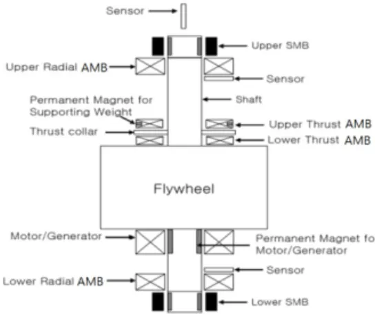
II. Design and manufacture of AMB and SFESS Fig. 1 shows the schematic diagram of the SFESS.
The SFESS is composed of a flywheel for energy
storage, a thrust bearing for levitating flywheel, the radial AMB for vibration control of axis and a motor/generator for energy conversion. Since the AMB is open-loop unstable, the position of the rotor is measured by a set of sensors located at the bottom and top of the rotor, and delivered to the controller.
The thrust AMB is a hybrid type where the weight of the rotor is supported by permanent magnet while an electromagnetic actuator generates the dynamic control forces. The axial motion of the rotor is also measured by a position sensor.
Fig. 1. Schematic diagram of SFESS with AMB.
2.1 Design and manufacture of radial AMB The radial AMB was designed to hetero-polar type having an eight-pole. Two adjacent poles are wired in series and two opposing pairs control each axis of the bearing. We employed the bias linearization method for the control of the radial AMB [3], where the current in each pair of coils is the sum of the constant bias current and the control current. If this method is used, the static load capacity of the radial AMB can be written as [4]
0 2
max
μ
sat g
B F = A
(1)
where Ag is the pole face area and Bsat is the saturation flux density of the bearing stator material.
Since the rotor spins vertically, the static force on the
bearing would not be large. The current design of the AMB has the pole face area of 8.8 cm2, which results in the static load capacity of approximately 1000 N per AMB, assuming the saturation density of 1.2 T.
Since there are two AMBs in the system, the total static load capacity in the radial direction is 2000 N.
The dynamic load capacity is related to the force slew rate of the AMB. Assuming that the main cause of the dynamic load is the unbalance disturbance, the maximum force slew rate that the AMB must provide is
max max
Ω
=Fsync dt
dF
(2)
where Fsync is the synchronous force by unbalance and Ωmax the maximum running speed. Considering the measured unbalance of the prototype rotor and the maximum operating speed of 20,000 rpm, the required force slew rate is estimated to be 3 N/sec.
When switching power amplifiers are used to drive the AMB (which is typical for a large-scale system), the force slew rate of the AMB is approximately determined by the parameters of the power amplifiers that drive the bearing coils [4], which can be stated as
0 max max max
2 g
V I dt
dF = α
(3)
In equation (3), g0is the nominal air gap, Imaxthe maximum current, Vmaxthe maximum voltage of the amplifier. The biasing ratio α determines the bias current with respect to the maximum current. Using the force slew rate requirement stated above, we can calculate the parameters for the power amplifiers.
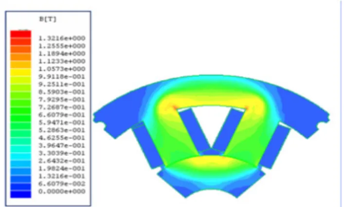
Fig. 2 shows the analytical result of magnetic flux density distribution of the designed radial AMB in case of 10 A of current and 0.6 mm of gap between the AMB pole and the wheel shaft. In this Fig, it was shown that the manufactured AMB was well designed without saturation. Through this result, we manufactured the radial AMB. Fig. 3(a) shows the manufactured radial AMB.
Fig. 2. Flux density of the radial AMB.
Fig. 3. The photograph of (A) the radial AMB and (B) the thrust bearing.
2.2 Manufacture of thrust bearing
In order to decrease the power consumption of the thrust actuator, the permanent magnets were used to carry the weight of the rotor. The design of the thrust bearing depends on the force and axial stiffness of this magnet pair, which can be calculated by the equivalent current sheet method [5]. The total axial force is the sum of the force by the actuator, the force by the permanent magnets and the weight of the rotor.
z W g
Wg z
g I N F A
pm pm z
g
z −
+ +
− +
= 2 2 2
0 2 2 0
) (
) ( 4 μ
(4)
where gpm is the nominal air gap between the permanent magnets, W the weight of the rotor, z the axial displacement from the nominal gap, Iz the control current to the thrust actuator. The axial stiffness can be obtained by differentiating equation (4) with respect to the axial displacement and evaluating it at zero displacement.
pm z g z
z z
g W g
I N A z
K F 2
2 03
2 2 0 0
−
∂ =
−∂
=
=
μ (5)
Assuming that the maximum static loading on the thrust actuator is 1 G, we can determine the size of the actuator using equation (1). Fig. 3(b) shows the manufactured thrust AMB.
2.3 Control system design
Since the AMB is open-loop unstable, we need a feedback controller for stable operation. With the dynamic model, we can design the controller. We designed a proportional-derivative (PD) type controller. The controller was embodied using the xPC which was a real time digital control system.
Fig. 4. Block diagram of control system.
Fig. 4 shows the block diagram of control system.
The controller was embodied using the MATLAB/
Simulink in the Host PC. The target PC obtains a sensor signal through the A/D, and after calculating the appropriate command value, the value is transfer to the current amplifier through the D/A. The current amplifier generates the current which is proportional to the controller command and transmits its current to the coil of the AMB.
2.4 Manufacture of SFESS
To assess vibration suppression ability of the AMB, a high speed rotation test is performed through its application in the large scale SFESS.
Fig. 5 shows the completed SFESS including the flywheel, the radial AMB, the thrust bearing and the motor/generator. The rotating body including the flywheel was about 425 kg and its inertia moment was 13.2 kg•m2. The wheel shaft made of SUS304.
Total length was 1,119 mm and diameter of the wheel was 580 mm.
Fig. 5. The photograph of (A) completed SFESS (B) rotating body with flywheel.
III. Test results and discussion
To prove validity of the design results of radial AMB, the magnetic force by the FEM analysis in design stage was compared with that by the experimental measurement after manufactured.
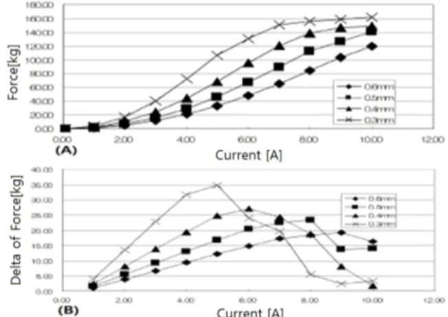
Fig. 6. The simulation results of (a) force measurement (b) variation of force for the different.
Fig. 6 shows the simulation results using the FEM analysis for magnetic force according to input current change (0~10 A) and gap change (0.3~0.6 mm) between the actuator and the flywheel shaft. 120 kgf of force was shown in case of 10 A in 0.6 mm of gap.
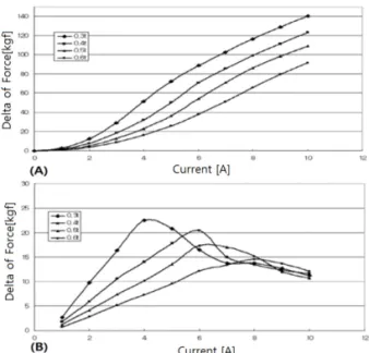
To measure magnetic force of the manufactured radial AMB according to input current and gap change, we made the test rig like Fig. 7. After putting
the measured pole down, flowing the current in the coil of measured pole. Then the pole pull the shaft in Fig. 7 and load cell in Fig. 7 measure the magnetic force.
Fig. 8 shows the experimental measurement results using the test rig in Fig. 7 for measuring magnetic force according to input current change and gap change. 95 kgf of force was shown in case of 10 A in 0.6 mm of gap. This difference of both results is due to manufacture errors, measurement error and difference between a property value of the Si-steel used in the FEM analysis and used in manufacture.
But the trend of magnetic saturation by simulation results was similar to that by the experimental results.
Fig. 7. Test rig for measuring magnetic force of radial AMB.
Fig. 8. The experimental test results of (a) force measurement (b) variation of force for the different current and different gap.
As the AMB system is fundamentally unstable, feedback controller is needed for stable operation. To select gain of PD controller and to design proper filter, we must know the dynamics of the system.
Initial PD gain can be selected using state space model of magnetic bearing. If the flywheel can be levitated using initially selected PD gains, frequency response of AMB can be measured. The controller was structured using xPC system of Mathworks. The sampling rate was 10 kHz. We measured frequency response using sine swept method to 5 kHz. Fig. 9 shows the block diagram for measuring frequency response.
Fig. 10, Fig. 11 and Fig. 12 show the measured frequency responses for thrust AMB, radial upper and lower AMB respectively. The measured frequency responses include dynamics for the AMB, the power amp and the sensor. The frequency responses were measured in stationary state after levitating the flywheel. The result for thrust AMB frequency response in Fig. 10 had no critical mode.
Thus any filter design does not need.
Fig. 9. Block diagram for sine swept method.
Fig. 10. Open loop bode plot of the measured frequency response for thrust AMB.
Fig. 11. Open loop bode plot of the measured frequency response for upper radial AMB without notch filter.
As shown in Fig. 11, the upper radial AMB without a notch filter has 1st bending mode having magnitude of 3.4 dB around 610 Hz. And lower radial AMB without notch filter in Fig. 12 has 1st bending mode having magnitude of -9.6 dB around 610 Hz and magnitude of 0.15 dB around 750 Hz.
We tuned the PD gain using initial gain obtained using state space model of magnetic bearing. We obtained P-gain 16.7 and D gain 0.02. The notch filters were designed that magnitude of 1st bending mode of open loop system becomes under -15 dB.
The designed digital notch filter was as following
6 5
4 3 2 1
6 5
4 3 2 1
8655 . 0 9 . 4 97 . 11 1 . 16 56 . 12 395 . 5 1
9306 . 0 144 . 5 27 . 12 11 . 16 27 . 12 144 . 5 9306 . 0
−
−
−
−
−
−
−
−
−
−
−
−
+
− +
− +
−
+
− +
− +
−
z z
z z z z
z z
z z z z
(6)
Fig. 12. Open loop bode plot of the measured frequency response for upper radial AMB without notch filter.
Fig. 13. Open loop bode plot of the measured frequency response for upper radial AMB with notch filter and PD controller.
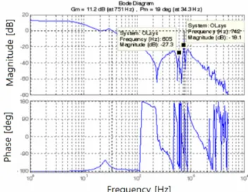
Fig. 14. Open loop bode plot of the measured frequency response for upper radial AMB with notch filter and PD controller.
Fig. 13 and 14 show the upper and lower open loop bode plot after applying the obtained PD gain and the designed notch filter. In the open loop bode plot of Fig. 13, the magnitude in 1st bending around 610 Hz of the upper radial AMB was -20.4 dB. And In the open loop bode plot of Fig. 14, the magnitude in 1st bending around 610 Hz of lower radial AMB was -27 dB and the magnitude in 2st bending around 750 Hz of lower radial AMB was -18 dB. We were confirmed that the notch filters for upper and lower AMB well designed. Fig. 15, and Fig. 16 show the nyquist plot to confirm the stability of the system.
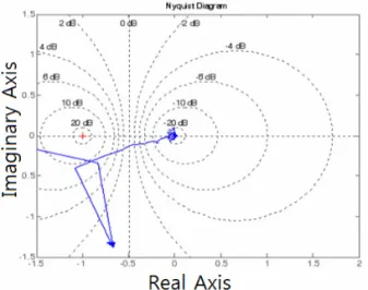
Fig. 15. Nyquist plot of upper radial AMB.
Fig. 16. Nyquist plot of lower radial AMB.
Fig. 17. SISO block diagram of AMB system.
Fig. 18 show current input and the orbits in the cylindrical mode (1,200 rpm), the conical mode (3,000 rpm) and the high speed region (10,000 and 15,000 rpm). In all rotation speed region, the input current did not exceed 3 A ±1 A. The 3 A is the bias current and the ±1 A is the control current. It was shown that the frequency of the input current came to
be high according to increase of rotation speed of the flywheel. This means that the designed AMB is well manufactured and the designed controller is well operated in high speed rotation.
Fig. 18. Current inputs and orbits according to rotation speed.
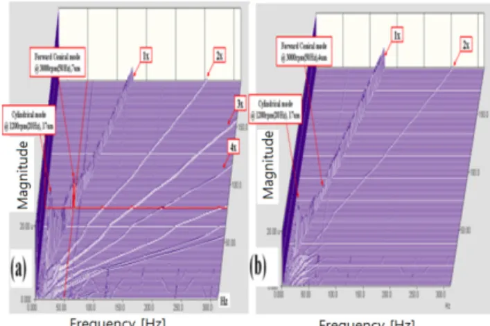
To assess vibration suppression ability of the AMB, a high speed rotation test was performed through its application in the large scale SFESS. Fig. 19 and Fig.
20 shows the vibration control results of the flywheel shaft in low rotational speed region and high rotational speed region respectively. The proposed AMB in the large scale SFESS had enough vibration suppression ability for the cylindrical mode in 1,200 (rpm) and the conical mode in 3,000 (rpm). And the average vibration value by 15,000 rpm was less than 10 μm. This value will be the world's highest record in large scale SFESS.
Fig. 19. Waterfall plot (a) upper part and (b) lower part in low rotation speed region (0~7000 RPM).
Fig. 20. Waterfall plot (a) upper part and (b) lower part in high rotation speed region (6000~15,000 RPM).
IV. Conclusions
In this paper, we designed the AMB and the controller which have maximum performance and minimum power consumption for applying large scale SFESS. Through comparison between the FEM analysis results for design model and experimental test results for manufactured AMB, exactness of the design result was verified. Selection of the PD controller gains and the filter design using system identification through sine swept test were performed.
Through the high speed rotation test after applying to
large SFESS, it was confirmed that the PD controller, the notch filters for upper and lower AMB well designed and vibration suppression ability was very excellent despite little input current. The vibration magnitude of wheel axis was 10 μm at 15,000 RPM.
References
[1] D. J. You, S. M. Jang, J. P. Lee and T. H. Sung,
“Dynamic performance Estimation of high-power SFESS using the operating torque of a PM synchronous Motor/generator”, IEEE Trans. Magnetics, Vol. 44, No. 11, pp. 4155-4158, 2008
[2] J. P. Lee, B. J. Park, Y. H. Han, S. Y. Jung and T. H.
Sung, “Energy loss by drag force of superconductor flywheel energy storage system with permanent magnet rotor”, IEEE Trans. Magnetics, Vol. 44, No. 11, pp. 4397-4400, 2008
[3] E. H. Maslen and D. C. Meeker, “Fault Tolerance of Magnetic Bearings by Generalized Bias Current Linearization”, IEEE Trans. Magnetics, vol. 31, pp.
2304-2314, May 1995.
[4] E. H. Maslen, P. Hermann, M. Scott, and R. R.
Humphris, “Practical limits to the performance of magnetic bearing: peak force, slew rate, and displacement sensitivity”, NASA Conference on Magnetic Suspension Technology, NASA Langley Research Center, Hampton, VA, 1988.
[5] C. Chen et al, “A Magnetic Suspension Theory and Its Application to the Heart Quest Ventricular Assist Device”, Artif. Organs, vol. 26, pp. 947-951, 2002.
[6] B. C. Park, S. Y. Jung, S. C. Han, J. P. Lee, Y. H. Han, and B. J. Park, “Simulation and Experimental Analysis of Magnetic Levitation Relative Stability for the Flywheel Energy Storage”, Trans. KIEE. Vol. 59. No.
9, pp. 1605-1610, Sep 2010.
[7] S. Y. Yoo, C. H. Park, S. K. Choi, J. P. Lee and M. K.
Nho, “Validation of Flexible Rotor Model for a Large Capacity Flywheel Energy Storage System”, Trans.
KSME. Vol. 32. No. 12, pp. 1096-1101, 2008.