1. INTRODUCTION
As the product life cycles decline drastically, technological leadership of the highest possible quality is required in order to react to the constantly increasing innovation dynamics. Engineers have to decrease the time for construction and evaluation of the prototypes. A mainly computer-based development of products - using 3D CAD systems - offers many advantages regarding the optimization of the time, costs and quality. But on the other hand they quickly leads to a restricted, reduced perception of the product during the development process. Therefore digital mock-ups (DMU) require virtual environments (VE) to improve the perception of the computer-based models, respectively the product. [1][2][3]
As the cumulative amount of spent fuel increases, the reliable and effective management of the spent fuel has become a world-wide mission. At the Korea Atomic Energy Research Institute (KAERI) considerable R&D effort is being made to develop management technology that will enhance the environmental friendliness and proliferation resistance as well as maximize the use of the available energy resources. For this mission, KAERI is developing the Advanced Spent Fuel Conditioning Process (ACP) as a pre-disposal treatment process for spent fuel. This technology involves the process of reducing the uranium oxide by lithium in a high temperature molten salt bath. Equipment used for such a spent fuel recycling and management process must operate in intense radiation fields as well as in a high temperature. Remote operation has played a significant role in this process because of the combined chemical and radiological contamination. Furthermore, a remote operation is expected to play a stronger role in future works.
Conventional approach to the development of the process and the remote maintenance technology is to fabricate the process equipment on the same scale as the real environment and demonstrate the remote handling operation using simulated fuel called a mock-up test. But this mock-up test is
expensive and time consuming, since the design may need to be modified and the equipment fabricated again to account for the problemsfound during a testing. To deal with this problem, we developed a digital mockup for the ACP. Also, for an effective utilization of the digital mockup, we developed user interface modules such as the data acquisition and display module and the external input device interface module.
2. ESTABLISHMENT OF THE DIGITAL MOCKUP FOR THE ACP 2.1 Overview of the ACP
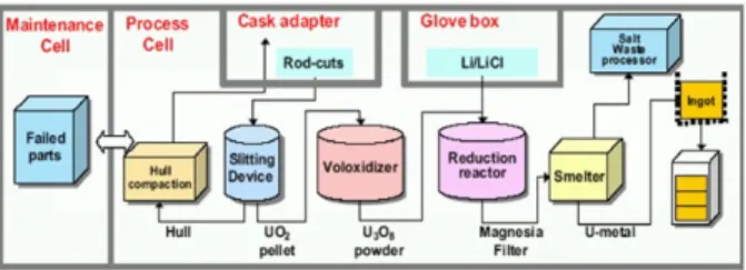
The reliable and effective management of spent fuel has become a worldwide mission. One of the alternatives is pyroprocessing. Pyroprocessing recycles the uranium resources that reside in the spent fuel. KAERI is also developing this process namely the ACP. The process flow chart of the ACP is shown in Fig. 1.
Figure 1. The process flow chart of the ACP.
The objective of the ACP is to treat the spent fuel in a molten salt (LiCl) bath to remove the volatile and high-heat load fission products and to convert the spent fuel into a metallic form more suitable for disposal in a repository. The process is to treat a high radioactive material including spent nuclear fuel. Therefore, this process is conducted in a sealed facility, called a hot cell. The ACP process consists of several
Development of the Interface Module for an Effective Application of a
Digital Mockup
TaiGil Song*, SungHyun Kim**, GwangMook Lim***, JiSup Yoon**** and SangHo Lee*****
Spent Fuel Technology Development Division, KAERI, Daejeon, Korea (* Tel: 82-42-868-2083; Fax: 82-42-868-2854; E-mail: [email protected]) (** Tel: 82-42-868-8877; Fax: 82-42-868-2854; E-mail: [email protected]) (*** Tel: 82-42-868-2071; Fax: 82-42-868-2854; E-mail: [email protected]) (**** Tel: 82-42-868-2855; Fax: 82-42-868-2854; E-mail: [email protected])
Dept. of Computer Sciense, Chungbuk University, Chungju, Korea
(*****Tel: 82-43-261-2253; Fax: 82-43-276-2253; E-mail: [email protected])
Abstract: As the cumulative amount of spent fuel increases, the reliable and effective management of the spent fuel has become a world-wide mission. For this mission, KAERI is developing the Advanced Spent Fuel Conditioning Process (ACP) as a pre-disposal treatment process for spent fuel. Conventional approach to the development of the process and the remote operation technology is to fabricate the process equipment on the same scale as the real environment and demonstrate the remote handling operation using simulated fuel called a mock-up test. But this mock-up test is expensive and time consuming, since the design may need to be modified and the equipment fabricated again to account for the problemsfound during a testing. To deal with this problem, we developed a digital mockup for the ACP. Also, for an effective utilization of the digital mockup, we developed user interface modules such as the data acquisition and display module and the external input device interface module. The result of this implementation shows that a continuous motion of the manipulator using the external device interface can be represented easily and the information display screens responded well to the simulation situation.
Keywords: virtual environment, digital mock-up, advanced spent fuel conditioning process(ACP), LLTI, interface module
ICCAS2005 June 2-5, KINTEX, Gyeonggi-Do, Korea
ICCAS2005 June 2-5, KINTEX, Gyeonggi-Do, KOREA
equipment such as a slitting device, a voloxidizer, a reduction reactor, and a smelting furnace. [5]
2.2 Development tool for the DMU
For developing the DMU, we used the ENVISION software. ENVISION is a product of the Dassault Co. and is a computer based robotic workcell simulation package for a design, evaluation, and an analysis. The ENVISION has two simulation languages and a low-level interface library such as GSL(Graphic Simulation Language) and CLI (Command Line Interpreter) and LLTI(Low Level Telerobotic Interface).
The GSL is a procedural language used to control the behavior of the simulation models. GSL incorporates conventions commonly used in high-level computer languages with specific enhancements for a model’s motion and simulation. The CLI is a powerful communication, command, and control system for accessing and operating an ENVISION system. It is accessible from both inside and outside the ENVISION menu system. LLTI uses a remote tele-operation with an on-line parallel monitoring of external devices. This process uses an on-line, bidirectional communication to provide a realistic, real-time simulation that reflects changes in the working environment as the work progresses. [8]
2.3 Building the virtual devices of the equipment for the ACP
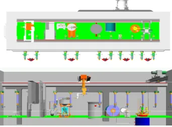
Figure 2 shows the process flow chart for building a DMU using the ENVISION packages. The first stage for building the virtual device is a 3D modeling. Figure 3 shows the 3D model of the process equipment and the remote handling device for the ACP. After modeling the process and remote ooperation/maintenance equipment, a virtual device is created by assigning the kinematics to a part model.
Figure 2. The process flow chart for building the digital mockup.
The motion destination position of a virtual device model is represented by a tag point which is a Cartesian coordinate frame with x, y, and z axes. To determine the position of a tag point in the layout, a part model of a virtual device model must be used to attach the tag point. With the attachment, the position of a tag point can be determined with respect to the base coordinate system of the part model of the device model to which the tag point is attached.
A virtual device’s motion represents a movement of the base frame or TCP frame of a device model to a tag point in the layout world. To generate this type of motion, the device model must have inverse kinematics. In this category, a manipulator model represents the general case, where the TCP frame of the manipulator model is required to move to a tag point defined in the workcell.
Figure 3. Built 3D model of the process equipments and remote handling devices for the ACP.
2.4 Establishment of the DMU for the ACP
For the establishment of the DMU, the process equipment and maintenance devices are modeled in 3-D graphics and the appropriate kinematics are assigned. As described above, several virtual devices are created. As shown in figure 4, the DMU of the ACP is established using ENVISION, which is to analyze and define the remote operation processes of the process equipment instead of using a real mockup. Also, the virtual workcell of the ACP is implemented to the graphical environment, which is almost identical to that of the real environment.
Figure 4. Established digital mockup for the ACP. The virtual device simulates the real device and should be tested before laying out the virtual work cell. In the DMU, the virtual device of the master-slave manipulator is mounted on to the hot cell wall and the telescopic servo manipulator (TSM) is attached to a transporter such as a crane. Also, several virtual devices such as a crane, TSM, voloxidizer, reduction reactor, uranium melting furnace, non-destructive assay system, etc., are arranged in the hot cell.
The virtual devices are assigned with various mobile attributes such as a relative position, kinematic constraints, and a range of mobility. A jogging motion of each joint of them is tested on the DMU.
3. DEVELOPMENT OF THE INTERFACE MODULE FOR THE DMU
The virtual devices in the DMU are activated only by the GSL and CLI or a jogging motion. Therefore, one simple
ICCAS2005 June 2-5, KINTEX, Gyeonggi-Do, KOREA
motion of the virtual device such as a TSM requires numerous sets of input data for each joint. Thus, a continuous motion of the TSM cannot really be represented. Also, users require various information for an effective use and for and accurate result of the analysis of the DMU. To deal with this problem, in this research, we developed an interface module. [4][6]
As shown in Fig 5, the interface module has the client-server architecture on the PC platform The interface program of the external input device with a 6 DOF is designed using the LLTI based on the TCP/IP network and the user information display interface module is developed using the ENVISION AXXESS library[8] on the MS Visual C++ platform.
This interface module consists of the external input device interface and the user information display interface. The external input device interface module should be allowed to input the 6 DOF data of the external input device such as the phantom device through the LLTI. The interface routine is designed to receive the 6 DOF input data and to create the data structure according to the LLTI data specification.
As shown in Fig 6, the user information display interface module is developed by using the ENVISION Axsess API, which is a flexible API framework based on DLL. Using the Axxess API, a user can easily integrate the developing software with the ENVISION kernel. In order to communicate with real time between DMU and user information interface module, we used the Axxess callback routine which is executed before and after a display in the world and when a world is created or destroyed
PC (Client)
TCP/IP
TCP/IP formatted LLTI6 DOF data & Axxess Event
DMU Server Onyx2/IBM IntelliStation Win2000 (OS) ENVIS-ION LLTI (TCP/ IP) AXXESS GSL&CLI Win2000 (OS) Device Inte rface (Visual C++) Ne twork (TCP/IP) AXXESS API Lib. PC (Client) TCP/IP
TCP/IP formatted LLTI6 DOF data & Axxess Event
DMU Server Onyx2/IBM IntelliStation Win2000 (OS) ENVIS-ION LLTI (TCP/ IP) AXXESS GSL&CLI Win2000 (OS) ENVIS-ION LLTI (TCP/ IP) AXXESS GSL&CLI Win2000 (OS) Device Inte rface (Visual C++) Ne twork (TCP/IP) AXXESS API Lib. Win2000 (OS) Device Inte rface (Visual C++) Ne twork (TCP/IP) AXXESS API Lib.
Figure 5. System configuration for developing the interface module for the DMU
Loading Control Dialog Select Device
(AxsDe vSelect)
Select Target
(AxsTagSelect)
Monitoring
(AxsWorl dCall backAdd)
Ge tDe vice TCP Ge tTag Infor m Ge tDistance Collision check
ENVISION
ENVISION DialogueDialogueControl Control
(Axs UserDll)
Loading Control Dialog Select Device
(AxsDe vSelect)
Select Target
(AxsTagSelect)
Monitoring
(AxsWorl dCall backAdd)
Ge tDe vice TCP Ge tTag Infor m Ge tDistance Collision check
ENVISION
ENVISION DialogueDialogueControl Control
(Axs UserDll)
Figure 6. The function diagram for the user information display interface module
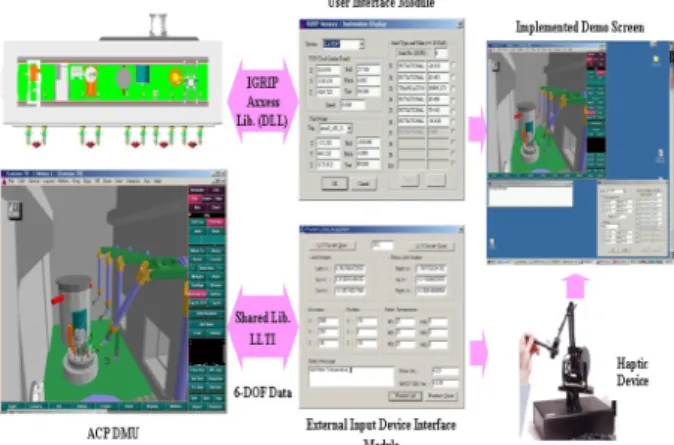
As shown in Fig 7, to demonstrate the applicability of the interface module, the developed system has been applied to a
phantom device and the ACP DMU. To activate the external input device interface system, a set of user I/O is designed including the LLTI for connecting the Phantom device. [7]
From the result of the demonstration, the external input device interface module communicated well with the Phantom device through the LLTI and the virtual manipulator of the DMU activated well accurately according to the received 6 DOF data. Also, the information display module responded well to the event of the DMU in a real-time
Figure 7. Implementation of the developed interface module for DMU.
4. CONCLUSION
In this research, we established the DMU for the ACP. Also, for improving the user interface and its effectiveness, we developed an interface module for the DMU. The result of this implementation shows that a continuous motion of the manipulator using the external device interface can be represented easily and the information display screens responded well to the simulation situation.
ACKNOWLEDGMENTS
The authors are grateful for the support provided by a grant from the Atomic Energy R&D Program of the Ministry of Science and Technology in Korea.
REFERENCES
[1] A. Raneda, M. Siuko, T. Virvalo. “A virtual reality human-machine interface for teleoperation,” Proc. Int. Conf. On Machine Automation ICMA2000, 561-566, Osaka, Japan, 2000
[2] Frank S. Cheng, “A Methodology for Development Robotic Workcell Simulation Models,” Proc. of the 2000
Winter Simulation Conference, pp. 1265-1271, 2000
[3] Yudaka Omura, etc., "Virtual prototyping for canister receiving devices of high level waste storage facility",
Proc. of '99 DENEB User Meeting for Korean Users,
1999
[4] Dr. Antal K Bejczy, “Calibrated Virtual Reality in Telerobotics”, Proc. of 5th International Workshop on
Robotics in Alpe-Adria-Danube Region, pp. 35-47, 1996
[5] Y, J. Shin, etc., "Development of Advanced Spent Fuel Management Process", KAERI/RR- 2128/2000, 2000. [6] S. J. Yoon, Simulation and Simulator, Sunhaksa, 2003 [7] SensAble, “Phantom Premium User’s Guide”, 2003 [8] Deneb, "ENVISION User Manual and Tutorials", 1995.