• 검색 결과가 없습니다.

ORIGINAL ARTICLE

N/A
N/A
Protected

Academic year: 2021

Share "ORIGINAL ARTICLE"

Copied!
13
0
0

로드 중.... (전체 텍스트 보기)

전체 글

(1)

eISSN 2384-1230 Clin J Korean Assoc Orthod 2019;9(2):59-71 https://doi.org/10.33777/cjkao.2019.9.2.59

ABSTRACT

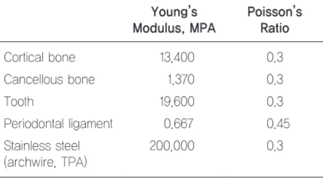
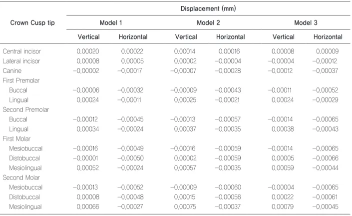
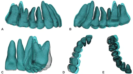
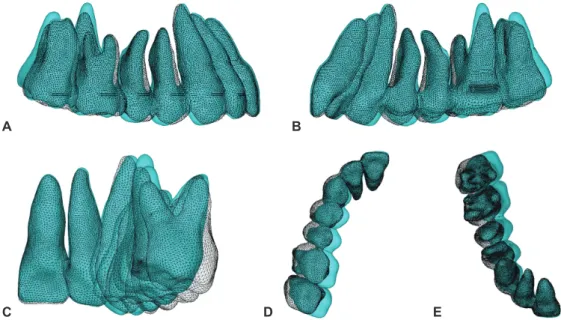
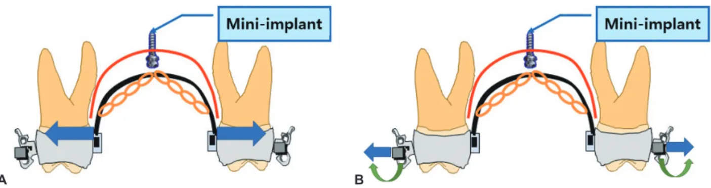
Objective This study evaluated the effect of the antero-posterior position of the midpalatal orthodontic mini-implant during maxillary posterior teeth intrusion using three-dimensional finite element model (3D-FEM) analysis. Methods A 3D-FEM was constructed from the computed tomography (CT) data of an adult male patient. Three simulation models were constructed according to the midpalatal mini-implant position: Model 1, at the interproximal level of the second premolar and first molar; Model 2, at the mesiopalatal cusp level of the first molar; and Model 3, at the interproximal level of the first and second molars. A 200-g force was applied from the bilateral hooks of the transpalatal arch (TPA) to the location of the mini-implant. Results In all models, the whole maxillary teeth showed intrusive movement, most at the second molar. As the mini-implant was positioned more posteriorly, intrusive displacement of the posterior teeth increased, while the intrusion and labioversion of the anterior teeth decreased. The palatal tipping movement of posterior teeth was remarkable. The highest stress value was shown on the trifurcation and palatal root surface area of the first molar. Conclusion A posteriorly positioned midpalatal mini-implant was more effective to intrude the maxillary posterior teeth without undesirable anterior teeth intrusion or labioversion. Expansion or buccal torque bending of the TPA could prevent the palatal tipping of the posterior teeth. (Clin J Korean Assoc Orthod 2019;9(2):59-71)

Key words FEM, Micro-implant, Orthodontic mini-implant, Tooth movement, Midpalatal mini-implant, Intrusion

ORIGINAL ARTICLE

Effect of Antero-Posterior Position of the Midpalatal Mini-Implant on the Intrusion of Maxillary Posterior Teeth:

A Three-Dimensional Finite Element Analysis

Kwang-Hyo Choi,

1,2

Il-Hyung Yang,

2,3

Seung-Hak Baek,

2,3

Sug-Joon Ahn,

2,3

Won-Hee Lim,

2,3

Shin-Jae Lee,

2,3

Tae-Woo Kim

2,3

1

Honors Orthodontic Clinic, Seoul, Korea

2

Department of Orthodontics, School of Dentistry,

3

Dental Research Institute, Seoul National University, Seoul, Korea

Corresponding author: Tae-Woo Kim Department of Orthodontics, School of Dentistry, Seoul National University Dental Hospital,

101 Daehak-ro, Jongno-gu, Seoul 03080, Korea Tel: +82-2-2072-3317 Fax: +82-2-2072-3817 E-mail: [email protected] Received: March 25, 2019 / Revised: April 15, 2019 / Accepted: April 15, 2019

Dr. 최 광 효 Dr. 양 일 형 Dr. 백 승 학 Dr. 안 석 준 Dr. 임 원 희 Dr. 이 신 재 Dr. 김 태 우

(2)

Clin J Korean Assoc Orthod 2019;9(2):59-71

INTRODUCTION

An anterior open bite is a difficult problem to treat. Orthognathic surgery is indispensable in pa- tients with severe skeletal discrepancy, but in pa- tients with mild skeletal discrepancy, various ther- apeutic modalities have been proposed, such as extruding the anterior teeth with vertical elastics,

1

changing the occlusion plane via multi-loop arch- wire,

2

and intruding the posterior teeth with a bite block

3

or high-pull headgear.

4

Recently, intrusion of the posterior teeth with temporary anchorage device (TAD)-like miniplates

5,6

or mini-implants

7

has emerged as an effective technique for the cor- rection of anterior open bite. Intrusion of the max- illary posterior teeth makes the occlusion plane steeper, and successful counter-clockwise rota- tion of the mandible can close the bite. According to the position of TADs, there are various force mechanisms and device designs.

Intrusion of the maxillary posterior teeth using one midpalatal mini-implant with a transpalatal arch (TPA) is an effective method to treat anterior open bite (Figure 1),

8-10

and several clinical studies have been reported. However, in vivo studies could not assess the biomechanical aspects. Three-di- mensional finite element model (3D-FEM) anal-

ysis is necessary to evaluate biomechanical fac- tors such as displacement and stress distribution of structures with complex geometries in various loading and boundary conditions.

The position of the mini-implant on the midpal- atal suture line can affect the direction of force from the mini-implant to the bilateral hooks of the TPA. By controlling the vector of force, teeth movement could be changed in not only posteri- or but also anterior teeth that are engaged with a heavy archwire.

The aim of this study is to evaluate the effect of the antero-posterior position of a mini-implant during maxillary posterior teeth intrusion with a midpala- tal mini-implant and TPA using 3D-FEM analysis.

MATERIALS AND METHODS

From the computed tomography (CT) images (SCT-6800 TXL, Shimadzu Co., Tokyo, Japan;

1.0-mm slice thickness) of a patient with normal occlusion (24-year-old male), a 3D virtual model of the maxilla was reconstructed using 3D image processing software (MIMICS Version 7.10, Ma- terialise NV, Leuven, Belgium). In every slice of the CT scan, the image was divided into the teeth, cortical bone, and cancellous bone (Figure 2) by

Figure 1. Intrusion of posterior teeth using single midpalatal mini-implant with transpalatal arch.

(3)

Midpalatal Mini-Implant on the Intrusion of Maxillary Posterior Teeth: 3D EFM | Choi et al.

one investigator. Then, the data were reconstruct- ed to a 3D geometric model (stereolithography file format; STL) which was imported to the 3D-FEM analysis software (ANSYS 12.0, Swanson Analy- sis System, Houston, PA). The periodontal mem- brane was assumed to have a constant thickness of 0.25 mm around the teeth. However, there was a difference in the thickness of the cortical bone depending on the location, as shown by the CT da- ta. Brackets and a 0.019×0.025-inch stainless steel archwire were placed on the surface of the teeth.

The usage of CT images was carried out under the tenets of the Helsinki Declaration (Figure 3).

The TPA connecting the lingual surface of the bilateral first molars was designed with a 0.9-mm diameter (Figure 3). The TPA was consistently kept 5 mm from the palate to achieve clearance for the intrusive movement.

The basic 3D-FEM model—including the max- illary teeth, periodontal membrane, cortical and cancellous bone, bracket and archwire, and TPA- was created with a mesh of tetrahedral elements.

A total of 498,276 elements and 96,510 nodes were used for the model. The mechanical proper- ties used are shown in Table 1.

11,12

The interfaces

Figure 2. Materials used to assemble a model. Cortical bone (A), cancellous bone (B), PDL (C), teeth (D).

Figure 3. 3D-FEM. A, Frontal view. B, Occlusal view. C, Sagittal view.

A A

B B

C

C D

Table 1. Mechanical properties of the materials Young’s Modulus, MPA

Poisson’s Ratio

Cortical bone 13,400 0.3

Cancellous bone 1,370 0.3

Tooth 19,600 0.3

Periodontal ligament 0.667 0.45

Stainless steel (archwire, TPA)

200,000 0.3

(4)

Clin J Korean Assoc Orthod 2019;9(2):59-71

between the bracket and tooth, TPA and tooth, and bracket and archwire were defined as fully bonded surfaces. All the teeth of the dentition were inter- preted as one unit without interaction of the adja- cent teeth at the interproximal surface.

Three simulation models were created to simu-

late different positions of the midpalatal mini-im- plant (Figure 4). In Model 1, it was assumed that the mini-implant was located at the interproximal level between the second premolar and first molar (Figure 4A). In Model 2, the mini-implant was po- sitioned at the level of the mesiopalatal cusp of the

Figure 4. Three simulation models constructed according to the position of the midpalatal mini-implant. A, Model 1. Mini-implant at interproximal level between maxillary second premolar and first molar. B, Model 2. Mini-implant at level of first molar mesiopalatal cusp. C, Model 3. Mini-implant at interproximal level between first and second molars.

A B C

Table 2. Displacement on the crown cusp tip or incisal edge

Crown Cusp tip

Displacement (mm)

Model 1 Model 2 Model 3

Vertical Horizontal Vertical Horizontal Vertical Horizontal

Central incisor 0.00020 0.00022 0.00014 0.00016 0.00008 0.00009

Lateral incisor 0.00008 0.00005 0.00002 -0.00004 -0.00004 -0.00012

Canine -0.00002 -0.00017 -0.00007 -0.00028 -0.00012 -0.00037

First Premolar

Buccal -0.00006 -0.00032 -0.00009 -0.00043 -0.00011 -0.00052

Lingual 0.00024 -0.00011 0.00025 -0.00021 0.00024 -0.00029

Second Premolar

Buccal -0.00012 -0.00045 -0.00013 -0.00057 -0.00014 -0.00065

Lingual 0.00034 -0.00024 0.00037 -0.00035 0.00038 -0.00043

First Molar

Mesiobuccal -0.00016 -0.00049 -0.00016 -0.00059 -0.00014 -0.00065

Distobuccal -0.00001 -0.00050 0.00002 -0.00059 0.00005 -0.00066

Mesiolingual 0.00052 -0.00024 0.00057 -0.00035 0.00059 -0.00044

Second Molar

Mesiobuccal -0.00013 -0.00052 -0.00009 -0.00060 -0.00004 -0.00065

Distobuccal 0.00008 -0.00048 0.00015 -0.00056 0.00022 -0.00061

Mesiolingual 0.00066 -0.00027 0.00075 -0.00037 0.00079 -0.00045

Vertical displacement: (+) intrusive, (-) extrusive, Horizontal displacement: (+) forward, (-) backward.

(5)

Midpalatal Mini-Implant on the Intrusion of Maxillary Posterior Teeth: 3D EFM | Choi et al.

first molar (Figure 4B). Finally, in the third mod- el, the mini-implant was positioned at the inter- proximal level between the first and second mo- lars (Figure 4C).

In each simulation model, the intrusion force of 200 g was activated from the bilateral hooks of the TPA to the assumed position of the mini-im- plant. The initial displacement of the teeth and the Von Mises stress distribution along the root sur- face were evaluated. To determine the amount of tipping movements of teeth, displacements of the nodes at the root apexes and the cusp tips of every tooth were assessed separately.

RESULTS

Displacements and Von Mises stress distribu- tions at the crown cusp tips and root apexes in each tooth of the simulation models are shown in Table 2 and 3.

For the evaluation of displacement, Model 1 showed the maximum value of intrusive dis- placement at the mesio-lingual cusps of the mo- lars (0.000656 mm) with an increase of displace- ment value distributed from the anterior teeth to the posterior directions. In all posterior teeth, in- trusive displacements of the buccal cusps were smaller than those of the palatal cusps. Some of the buccal cusps even showed extrusive displace- ment. In the antero-posterior direction, the central incisor showed the highest forward displacements of 0.000221 mm among all models (Figures 5, 6).

In Model 2, the maximum intrusive displace- ment on the second molar (0.000746 mm) and the palatal tipping tendency were also seen, as in the first model. However, the intrusion values of the posterior teeth increased considerably compared to the same teeth of the first model. The central in- cisor had a forward displacement of 0.000160 mm

(Figures 7, 8). Table 3.

Displacement and Von Mises stress on the root apexes Root apex

Model 1 Model 2 Model 3 Displacement (mm) Stress (N/mm

2

) Displacement (mm) Stress (N/mm

2

) Displacement (mm) Stress (N/mm

2

) Vertical Horizontal Vertical Horizontal Vertical Horizontal Central Incisor 0.00011 0.00004 0.00038 0.00009 0.00006 0.00037 0.00007 0.00007 0.00038 Lateral incisor 0.00012 0.00009 0.00106 0.00011 0.00011 0.00120 0.00010 0.00013 0.00128 Canine 0.00007 0.00015 0.00153 0.00006 0.00017 0.00169 0.00004 0.00018 0.00177 First Premolar 0.00004 0.00012 0.00083 0.00003 0.00012 0.00088 0.00002 0.00011 0.00088 Second Premolar 0.00002 0.00016 0.00152 0.00002 0.00015 0.00153 0.00001 0.00012 0.00146 First Molar Mesial -0.00009 0.00000 0.00076 -0.00008 -0.00002 0.00074 -0.00006 -0.00004 0.00069 Distal -0.00011 -0.00003 0.00122 -0.00008 -0.00005 0.00119 -0.00005 -0.00006 0.00113 Palatal 0.00059 0.00026 0.00328 0.00065 0.00025 0.00346 0.00068 0.00022 0.00346 Second Molar Mesial -0.00004 0.00001 0.00173 0.00001 0.00002 0.00176 0.00006 0.00003 0.00171 Distal 0.00000 -0.00001 0.00096 0.00006 0.00000 0.00103 0.00012 0.00001 0.00107 Palatal 0.00072 0.00022 0.00249 0.00081 0.00020 0.00273 0.00084 0.00017 0.00282

(6)

Clin J Korean Assoc Orthod 2019;9(2):59-71 Clin J Korean Assoc Orthod 2019;9(2):59-71

D E

In Model 3, the maximum intrusive displace- ment was found on the second molar (0.000793 mm), and it was the highest value among all three models. As in the prior models, the palatal cusps showed more intrusion than the buccal cusps.

However, the actual intrusive displacement values on the buccal cusps were greater than the values of Models 1 and 2. The central incisor had a forward displacement of 0.000095 mm and was the small- est of the three models (Figures 9, 10).

Figure 5. Model 1. Displacements of maxillary teeth. A, Sagittal view (external). B, Sagittal view (lingual). C, Occlusal view. D, Coronal view (root side). Von Mises stress distribution. E, Sagittal view (external). F, Sagittal view (lingual). G, Coronal view (root side).

Figure 6. Model 1. Superimposition of the original (white mesh) and deformed model (color). The displacement of teeth was magni- fied by 500 times. A, B, Sagittal view (external and lingual). C, Coronal view (posterior side). D, E, Axial view (occlusal side and root side). All teeth in the dentition were intruded. Note the maximum displacement of the lingual cusp of the premolar and molar (B, C) and palatal tipping tendency (C-E).

A E

A

F B

G

C D

B

C

(7)

Midpalatal Mini-Implant on the Intrusion of Maxillary Posterior Teeth: 3D EFM | Choi et al.

Midpalatal Mini-Implant on the Intrusion of Maxillary Posterior Teeth: 3D EFM | Choi et al.

For the evaluation of stress distribution, Model 1 showed the highest stress with a maximum Von Mises stress of 0.089 N/mm

2

. The first molar had the highest stress in the dentition, especially on the trifurcation area and the palatal root surface,

which was adjacent to the force application site (Figure 5). In Model 2, the maximum stress was 0.088 N/mm

2

(Figure 7). The first molar had the highest stress, but the area was narrower than that in Model 1. In Model 3, the maximum stress value

D E

Figure 7. Model 2. Displacements of maxillary teeth. A, Sagittal view (external). B, Sagittal view (lingual). C, Occlusal view. D, Coronal view (root side). Von Mises stress distribution. E, Sagittal view (external). F, Sagittal view (lingual). G, Coronal view (root side).

Figure 8. Model 2. Superimposition of the original (white mesh) and deformed model (color). A, B, Sagittal view (external and lingual).

C, Coronal view (posterior side). D, E, Axial view (occlusal side and root side). Note the maximum displacement of the lingual cusp of the premolar and molar (B, C) and palatal tipping tendency (C-E).

A E

A

F B

G

C D

B

C

(8)

Clin J Korean Assoc Orthod 2019;9(2):59-71

of 0.082 N/mm

2

was lower than those of Models 1 and 2. The first molar showed the highest stress value in the dentition, but the area decreased and was the smallest of the three models (Figure 9).

DISCUSSION

Intrusion of teeth has been a difficult technique in orthodontics because of the complication in acquiring proper anchorage. TADs allowed cli-

D E

Figure 9. Model 3. Displacements of maxillary teeth. A, Sagittal view (external). B, Sagittal view (lingual). C, Occlusal view. D, Coronal view (root side). Von Mises stress distribution. E, Sagittal view (external). F, Sagittal view (lingual). G, Coronal view (root side).

Figure 10. Model 3. Superimposition of the original (white mesh) and deformed model (color). A, B, Sagittal view (external and lin- gual). C, Coronal view (posterior side). D, E, Axial view (occlusal side and root side). Displacements of the anterior teeth were de- creased further than they were in Models 1 and 2.

A E

A

F B

G

C D

B

C

(9)

Midpalatal Mini-Implant on the Intrusion of Maxillary Posterior Teeth: 3D EFM | Choi et al.

nicians to gain absolute anchorage more easi- ly. Intrusion mechanics using mini-implants on the buccal or palatal alveolar bone need several mini-implants or other accessory appliances to balance the force.

13

However, just one midpalatal mini-implant is enough to support the intrusion force for the bilateral posterior teeth. The midpala- tal suture area contains high-quality cortical bone, which contributes to the retention of the mini-im- plants. The area within 1 mm of the midpalate has the thickest bone available (over 5.0 mm in fe- males and 5.4 mm in males).

14

Moreover, the mid- palate area is safe because there is little danger of damaging anatomical structures, and it is covered with keratinized gingiva and thus less susceptible to inflammation. In a study using human cadaveric palatal bone, insertion sites parasagittally adjacent to the first molars showed higher primary stability of mini-implants.

15

Several studies on the intrusion of the posteri- or teeth using orthodontic mini-implants

8-10

have been reported in the form of case reports or clini- cal assessments, but only a few have been reported in the form of 3D-FEM analysis. 3D-FEM analysis is valuable to evaluate biomechanical factors such as displacement and stress distribution of struc- tures with complex geometries in a specific con- dition. There was a 3D-FEM study on a sectional posterior teeth model,

13

but there has not yet been a full dentition 3D-FEM study about intrusion. In a clinical situation, intrusion of the posterior teeth can be conducted separately or together with an- terior teeth movement. Intrusion can be done si- multaneously with the leveling or space-closing procedure. Hence, 3D-FEM analysis of the full dentition engaged with an archwire is worthy of study. This study evaluated the effect of the ante- ro-posterior position of a midpalatal mini-implant on the intrusion of the maxillary posterior teeth connected with an archwire and TPA.

In 3D-FEM analysis, resemblance between the simulation model and the actual biomechanical environment is important to get a meaningful re- sult for the clinical application. In previous studies using 3D-FEM, models were generated from a la- ser scan of a dentiform.

16,17

Usually, the thickness of cortical and cancellous bone around the teeth was given in uniform or gradual depth.

13,15

Howev- er, the thickness of cortical bone varies depending on the location. Making a model based on actual patient data can result in a more realistic result. In a recent study of other subjects, FEM models were created based on patient CT data, but they were partial dentition models with only two teeth.

18

In this study, the model was generated from an adult male patient with normal occlusion to maximize the similarity of the models with maxillary den- tition. The areas of teeth, cortical bone, and can- cellous bone were addressed manually by tracing on every CT cut taken at 1.0-mm intervals in the three planes: frontal, sagittal, and coronal. This is an important precondition in tooth movement analysis.

On the labial side, a 0.019×0.025-inch stainless steel archwire was designed and bonded to the brackets of teeth. Every interface (i.e., teeth-brack- ets, brackets-archwire, teeth-TPA) was defined as a fully bonded surface to clearly indicate the ef- fect of biomechanics using a TPA for the intrusion of posterior teeth. In a clinical situation, posteri- or teeth intrusion in the dentition engaged with a heavy archwire can make the occlusal plane steep- er, facilitating open bite correction.

In all models, maximum Von Mises stress val- ues were observed in the trifurcation areas of the first molar (Figures 5, 7, 9). The maximum stress values were similar among the three models but greatest in Model 1 (0.089 N/mm

2

), then Model 2 (0.088 N/mm

2

), and lowest in Model 3 (0.082 N/

mm

2

). Another stress-increased site was the coro-

(10)

Clin J Korean Assoc Orthod 2019;9(2):59-71

nal third of the first molar palatal root. This area is adjacent to the connection of the TPA, where the intrusive force is transferred to the tooth. The maximum stress value was like that in a previous study using multiple mini-implants on the buccal and palatal sides simultaneously.

13

Root apexes are the sites where the intrusive force is condensed, and they can be critical sites of resorption.

19,20

The stress distribution is changed by the root geometries and the surface area as well as the applied force. In this study, increased stress values were shown in the palatal root apexes of the first and second molars. The value was larger in the first molar, which is directly connected to the TPA, than in the second molar. Although the dif- ference was slight, the highest value was shown in Model 3, then Model 2, and the lowest value was shown in Model 1. A more vertical portion of the applied force was delivered to the molars in Model 3 than those in the other models.

All the posterior teeth showed intrusive dis- placement (Table 2). Because all the teeth in den- tition were engaged by a rigid stainless steel arch- wire in this study, the anterior and posterior teeth moved simultaneously. The anterior teeth showed intrusive displacement as did the posteriors, but there was an increase of the displacement value distributed from the anterior teeth to the posterior directions.

In a recent 3D-FEM study,

17

the center of resis- tance of all maxillary dentition (CRM) was ap- proximately on the coronal third of the second premolar root. In this study, the intrusive force is concentrated on the hooks of the TPA connect- ing the bilateral first molars. The vector direc- tion of the force is from the hook of the TPA to the mini-implant (Figure 4). If the force passes through the rear side of the CRM, displacement of the posterior teeth increases like a lever arm. In this study, it is assumed that the CRM was situated

ahead of the first molar. In Model 2, the vector of force passed just above the first molar, and the pos- terior teeth were more intruded than the anterior teeth. In Model 1, as the force vector came closer to the CRM, the anterior teeth showed more ver- tical displacement than they did in Models 2 or 3.

In addition, the posterior teeth showed the small- est displacement among the three models. On the other hand, the force vector moved further back- ward from the CRM in Model 3, so the intrusive displacement was biggest in the posterior teeth but smallest in the anterior teeth in all models.

Extrusion of the upper incisors was reported during the intrusion of the posterior teeth when the whole arch was bonded because of a clockwise rotation of the whole maxillary dentition.

6,21,22

However, in this study, the incisors intruded even though the magnitude was lower than that of the molars. The position of the CRM and the displace- ment of teeth can vary depending on the applica- tion of orthodontic force, shape and size of the tooth, height or quality of alveolar bone, and even mechanical character of the archwire. The results of this study verified the possibility for intrusion of all maxillary dentition with a single midpalatal mini-implant.

A common palatal tipping of the teeth was ob-

served in all three simulation models. There was a

difference in the amount of displacement between

the buccal and palatal cusps of the posterior teeth

(Table 2 and 3). In the first molar, the mesiopala-

tal cusp showed the most intrusion. However, the

distobuccal cusp had only a slight intrusion, and

the mesiobuccal cusp even showed a slight extru-

sive displacement. This is because the intrusion

force acting on the lingual surface of the TPA

has both vertical and horizontal components. A

0.019×0.025-inch stainless steel archwire and a

0.9-mm stainless steel TPA were not enough to

resist the palatal tipping force. In order to resist

(11)

Midpalatal Mini-Implant on the Intrusion of Maxillary Posterior Teeth: 3D EFM | Choi et al.

this palatal tipping, additional mini-implants may be added to the buccal alveolar side to give a bal- ancing force.

13

However, careful expansion or buc- cal torque bending of the TPA or main archwire could resist the palatal tipping tendency without additional mini-implants on the buccal side (Fig- ure 11).

The incisal edge of the central incisor showed the most forward movement in Model 1, followed by Model 2, and the least in Model 3. This is be- cause the horizontal component appears on the sagittal plane in the force depending on the an- tero-posterior position of the mini-implant. When treating a patient with a Class Ⅱ open bite, when the mini-implant is placed forward, the anterior teeth are mechanically unfavorable because they are forced forward. Thus, it is advantageous to place the mini-implant backward.

In this study, the interactions between adjacent teeth were omitted. It is assumed that the dentition is tied with a heavy stainless steel archwire, which is suitable to see the overall change of the denti- tion when the intrusive force is given. This meth- od is meaningful in treating open bite by changing the occlusal plane through intrusion of the posteri- or teeth and related displacement of the other con- nected teeth. However, due to the assumption that the teeth are attached to each other, there is a dif-

ference in actual clinical situation. In some cases, the first and second molars are not connected, or connected loosely with a thin flexible archwire. In these situations, the most intrusive displacement and the palatal tipping will occur in the first mo- lar. This is consistent with the concentration of the strongest stress on the first molar in this study.

In real clinical situation, even if the teeth are fixed by a 0.019×0.025-inch archwire, there is a small but free movement due to the clearance be- tween the bracket slot and the archwire, and in- teractions between the teeth also occur. And even stainless steel archwire can be bent with heavy force. The inability to reproduce all these indi- vidual movements of the teeth in actual clinical practice is the limit of this study. The individual movements of the teeth can be larger if there is an extraction space. Intrusion of the posterior teeth could also be done in the extracted dentition in a clinical situation. The first or second premolar and second molar could be alternative options to ex- tract in the open bite patient. In this case, biome- chanical movement will be different from non-ex- tracted dentition, especially in teeth adjacent to the extraction site. Therefore, further biomechan- ical studies using 3D-FEM that allows interaction between teeth in various dental conditions are needed. The research on the type of labial arch-

Figure 11. Method to compensate for palatal tipping. A, Expansion of transpalatal arch. B, Expansion or buccal torque bending of archwire.

A B

(12)

Clin J Korean Assoc Orthod 2019;9(2):59-71

wire or the extraction of the teeth is to be studied in the second stage.

CONCLUSION

In this 3D-FEM analysis, intrusion mechanics using a midpalatal mini-implant and TPA were effective to intrude the bilateral posterior teeth.

Posteriorly positioned mini-implants were more effective to intrude the posterior teeth without un- desirable anterior teeth intrusion or labioversion, especially in the open bite patient. Although the teeth were bound with 0.019×0.025-inch stainless steel archwire and a 0.9-mm stainless steel TPA, there were palatal tipping movements of the mo- lars. Expansion or buccal torque bending of TPA could help to overcome the palatal tipping of pos- terior teeth.

Acknowledgments

This study was supported by grant No. 05-2013- 0008 from the Seoul National University Dental Hospital Research Fund.

REFERENCES

1. Rinchuse DJ. Vertical elastics for correction of anterior open bite. J Clin Orthod 1994;28:284.

2. Kim YH. Anterior openbite and its treatment with multiloop edgewise archwire. Angle Orthod 1987;57:

290-321.

3. Iscan HN, Sarisoy L. Comparison of the effects of passive posterior bite-blocks with different construction bites on the craniofacial and dentoalveolar structures.

Am J Orthod Dentofacial Orthop 1997;112:171-178.

4. Saito I, Yamaki M, Hanada K. Nonsurgical treatment of adult open bite using edgewise appliance combined with high-pull headgear and class III elastics. Angle Orthod 2005;75:277-283.

5. Umemori M, Sugawara J, Mitani H, Nagasaka H, Kawamura H. Skeletal anchorage system for open-

bite correction. Am J Orthod Dentofacial Orthop 1999;115:166-174.

6. Erverdi N, Keles A, Nanda R. The use of skeletal anchorage in open bite treatment: a cephalometric evaluation. Angle Orthod 2004;74:381-390.

7. Park HS, Kwon TG, Kwon OW. Treatment of open bite with microscrew implant anchorage. Am J Orthod Dentofacial Orthop 2004;126:627-636.

8. Kim TW, Kim H. Clinical Application of Orthodontic Mini-implant. Seoul: Myung Mun Publishing Co.; 2008, p. 157-211.

9. Xun C, Zeng X, Wang X. Microscrew anchorage in skeletal anterior open-bite treatment. Angle Orthod 2007;77:47-56.

10. Lee JS, Kim DH, Park YC, Kyung SH, Kim TK. The efficient use of midpalatal miniscrew implants. Angle Orthod 2004;74:711-714.

11. Tanne K, Miyasaka J, Yamagata Y, Sachdeva R, Tsutsumi S, Sakuda M. Three-dimensional model of the human craniofacial skeleton: method and preliminary results using finite element analysis. J Biomed Eng 1988;10:246-252.

12. Miyasaka-Hiraga J, Tanne K, Nakamura S. Finite element analysis for stresses in the craniofacial sutures produced by maxillary protraction forces applied at the upper canines. Br J Orthod 1994;21:343-348.

13. Çifter M, Saraç M. Maxillary posterior intrusion mechanics with mini-implant anchorage evaluated with the finite element method. Am J Orthod Dentofacial Orthop 2011;140:e233-e241.

14. Kang S, Lee SJ, Ahn SJ, Heo MS, Kim TW. Bone thickness of the palate for orthodontic mini-implant anchorage in adults. Am J Orthod Dentofacial Orthop 2007;131(4 Suppl):S74-S81.

15. Bourassa C, Hosein YK, Pollmann SI, Galil K, Bohay RN, Holdsworth DW, Tassi A. In-vitro comparison of different palatal sites for orthodontic miniscrew insertion: Effect of bone quality and quantity on primary stability. Am J Orthod Dentofacial Orthop 2018;154:809- 819.

16. Jang HJ, Roh WJ, Joo BH, Park KH, Kim SJ, Park YG.

Locating the center of resistance of maxillary anterior teeth retracted by Double J Retractor with palatal miniscrews. Angle Orthod 2010;80:1023-1028.

17. Jeong GM, Sung Sang-Jin, Lee KJ, Chun YS, Mo SS.

(13)

Midpalatal Mini-Implant on the Intrusion of Maxillary Posterior Teeth: 3D EFM | Choi et al.

Finite-element investigation of the center of resistance of the maxillary dentition. Korean J Orthod 2009;39:83-94.

18. Fernandes LC, Farinazzo Vitral RW, Noritomi PY, Schmitberger CA, José da Silva Campos M. Influence of the hyrax expander screw position on stress distribution in the maxilla: a study with finite elements. Am J Orthod Dentofacial Orthop 2019;155:80-87.

19. Harris DA, Jones AS, Darendeliler MA. Physical properties of root cementum: part 8. Volumetric analysis of root resorption craters after application of controlled intrusive light and heavy orthodontic forces:

a microcomputed tomography scan study. Am J Orthod

Dentofacial Orthop 2006;130:639-647.

20. Ari-Demirkaya A, Masry MA, Erverdi N. Apical root resorption of maxillary first molars after intrusion with zygomatic skeletal anchorage. Angle Orthod 2005;75:761-767.

21. Park HS, Kwon OW, Sung JH. Nonextraction treatment of an open bite with microscrew implant anchorage. Am J Orthod Dentofacial Orthop 2006;130:391-402.

22. Cousley RR. A clinical strategy for maxillary molar

intrusion using orthodontic mini-implants and a

customized palatal arch. J Orthod 2010;37:202-208.

수치

Figure 1.	Intrusion	of	posterior	teeth	using	single	midpalatal	mini-implant	with	transpalatal	arch.
Figure 2.	Materials	used	to	assemble	a	model.	Cortical	bone	(A),	cancellous	bone	(B),	PDL	(C),	teeth	(D)
Table 2.	Displacement	on	the	crown	cusp	tip	or	incisal	edge
Figure 6. Model	1.	Superimposition	of	the	original	(white	mesh)	and	deformed	model	(color).	The	displacement	of	teeth	was	magni- Model	1.	Superimposition	of	the	original	(white	mesh)	and	deformed	model	(color).	The	displacement	of	teeth	was	magni-fied	by	5
+4

참조

관련 문서

Objective: The purpose of this study is to determine the prevalence of sinus disease and abnormalities in patients scheduled for dental implant in maxillary posterior area

Panoramic radiographs taken with the new bite block showed better stability in inter-maxillary vertical space, antero-posterior position, and bilateral symmetry than

A Transpalatal arch on maxillary second molars was hung on distal side of posterior mini-implant to generate moments for distal root movement.. B Broken line represents

Conclusions: These results show that the periotest is a useful method for the evaluation of mini-implant stability, but it can only be applied to limited areas with thick cortical

Objective: This study investigated the skeletal and dentoalveolar changes after intrusion of maxillary posterior teeth using miniscrew implants during the treatment and

Objective: The purpose of this study was to investigate changes in the mandibular dental arch from presurgical orthodontic treatment and orthognathic surgery, and to evaluate

The axis changes of the maxillary central incisors according to the length of the anterior retraction hook under low and high orthodontic mini-implant traction in both models