Sensor-Based Path Planning for Planar Two-identical-Link Robots by Generalized Voronoi Graph
Ming-Lei Shao
1, Kyoo-Sik Shin
2*1Department of Mechanical Engineering, Hanyang University
2Department of Robot Engineering, Hanyang University
일반화된 보로노이 그래프를 이용한 동일 두 링크 로봇의 센서 기반 경로계획
소명뢰1, 신규식2*
1한양대학교 기계공학과, 2한양대학교 로봇공학과
Abstract The generalized Voronoi graph (GVG) is a topological map of a constrained environment. This is defined in terms of workspace distance measurements using only sensor-provided information, with a robot having a maximum distance from obstacles, and is the optimum for exploration and obstacle avoidance. This is the safest path for the robot, and is very significant when studying the GVG edges of highly articulated robots. In previous work, the point-GVG edge and Rod-GVG were built with point robot and rod robot using sensor-based control. An attempt was made to use a higher degree of freedom robot to build GVG edges. This paper presents GVG-based a new local roadmap for the two-link robot in the constrained two-dimensional environment. This new local roadmap is called the two-identical-link generalized Voronoi graph (L2-GVG). This is used to explore an unknown planar workspace and build a local roadmap in an unknown configuration space R2× T2 for a planar two-identical-link robot. The two-identical-link GVG also can be constructed using only sensor-provided information. These results show the more complex properties of two-link-GVG, which are very different from point-GVG and rod-GVG. Furthermore, this approach draws on the experience of other highly articulated robots.
요 약 일반화된 보로노이 그래프(GVG)는 자율 주행 로봇을 위한 일종의 로드맵으로서. GVG는 선서에다 받은 정보만 사용하여 작업 공간거리의 계산에 따라 정의를 한다. 로봇은 장애물까지의 최대 거리를 검출할 수 있기 때문에 포인트 뷰에 서 GVG의 최적은 정출 몇 장애물 회피이다. 로봇의 경우에는, GVG는 가장 안전적인 길이라고 할 수 있다. 따라서 높이 링크 로봇의 GVG가장거리에 대한 연구가 매우 필요하다. 기존 연구에서 점(point) 로봇을 위한 GVG(point-GVG)와 로드 로봇을 위한 GVG(rod-GVG)가 발표되었다. 이 논문은 더 고차원의 로봇인 두 개의 동일 링크가 관절로 연결된 (tow-identical-link; L2) 로봇을 위한 GVG(L2-GVG)에 대한 연구이다. L2-GVG는 미지의 평면 작업공간에서 움직이는 L2 로봇의 짜임새 공간 × 상에서 로드맵을 생성하되, 이전 연구와 마찬가지로 지역적 센서 정보만을 이용해 로봇이 스 스로 주행하면서 맵을 만들어 낸다. 이 논문에서는 이전 point-GVG와 rod-GVG에서는 나타나지 않는, 관절이 존재하여 생기 는 복잡한 특성에 대해서 분석한다. 이는 다관절 로봇으로의 확장에 중요한 초석이 될 것이다.
Key Words : Two-identical-link Robots, Sensor-based Path Planning, Generalized Voronoi Graph
This work was supported by Hanyang University.
*Corresponding Author : Kyoo-Sik Shin(Hanyang Univ.) Tel: +82-31-400-5245 email: [email protected]
Received November 17, 2014 Revised December 8, 2014 Accepted December 11, 2014
1. Introduction
This work considers sensor-base exploration for two-identical-link robots operating in a non-Euclidean configuration space ×. This algorithm produces a roadmap, it is called the two-identical-link generalized Voronoi graph (L2-GVG). Robot can use this roadmap to plan paths in the unknown environment.
Our approach is based on the Generalized Voronoi Graph (GVG), which is equidistant to two and more than to obstacles [1]. Hence, the GVG edge has the maximum distances to obstacles. It is the safest path for robot. This is a very meaningful for studying the GVG edges of the highly articulated robots. Now researchers focus more on GVG-based path planning for robot.
Nagatani and co-workers introduced a path-planning algorithm based on GVG for a car-like robot [2]. They explained the details of the evaluation function for solving the problem in which the existence of a minimum turning radius for a car-like robot may prevent it from following the GVG exactly [3].
Hoff and others developed the algorithms that combine GVG with a probabilistic method to define a roadmap for the robot [4-7]. Choset and Lee proposed a new roadmap called the rod-GVG. It was developed for a rod-shaped robot in a two-dimensional workspace in [8,9]. The rod-GVG is then defined as the set of points equidistant from three obstacles in configuration space SE(2).
In a further development, in this line of research is to consider the rigid bodies, Lee and Choset then presented the convex-GVG for guiding a convex body to explore an unknown planar workspace [10].
The rod-GVG and the convex-GVG are not always connected, so they need connected additional structures.
But it is quit surprising that the L2-GVG can connect very well. This is because that two-link robot has the high DOF, it is more flexible.
For sensor-based path planning in an unknown environment, the robot must systematically more about
detecting and computing the environment information.
This procedure requires only local sensor distance measurement data and is therefore practically implementable. We assume that the body of the two-identical-link robot is covered by sensors, and that the sensors ranges are infinite and that obstacles can be measured using a series of range sensors. The robot cannot know the number of obstacles directly, but can determine this by the number of local minima. So the robot can “see” the world. L2-GVG is useful means for implementing sensor-based motion-planning algorithms.
The robot construct an L2-GVG edge until it reaches the obstacles or a node, where there are branches to explore all edges emanation. We need explored all branches from this node, if the all nodes have been explored, the algorithm finishes. The L2-GVG is a roadmap as a network of one-dimensional curves in configuration space.
2. Two-identical-link robot and distance definitions
2.1 Definition of two-identical-robot
The two-identical-link robot L2 can be represented as the union of two rod-shape rigid bodies ∈
with a rotational joint P between them. The end points for rod are and P; the end points for rod are and P. The configuration space for the robot operating in a plane is four-dimensional R×T. The configuration of the robot can be parameterized by the joint point P and the two orientations of , i.e.,
∈R×T. Let be the set of points occupied by the a-th rod of the L2-robot at configuration . Then can be written as
∈
(1)where P is the position of the joint, L is the length of the rod .
We assume that all obstacles are taken to be convex obstacles, is denoted the workspace obstacles, where the subscripts ∈ is denoted the mark number of obstacle. In work configuration space, the configurations of robot do not intersect any obstacles.
[Fig. 1] Determination of the configuration of a two-link robot.
2.2 Distance function and gradient vector The distance function will be used to define the components of L2-GVG. We assume the boundary of the robot is covered by a series of rangesensors. The robot can accurately measure the closest point on robot to the closest obstacle. The work space distance between robot and an obstacle is defined as
∈∈
║ ║ (2) The distance gradient ∇ is represented as:
∇
⋅ × ⋅ ×
∈×
(3)
where and are the nearest points on the rod a and obstacle , respectively, and is the Kronecker delta
≠ (4) We assume that the boundaries of obstacles are slightly curve, this guarantee that the distance gradient is able to always obtain.
3. Definitions for L2-GVG
3.1 There-way equidistant faceWe define the L2-GVG edges by intersecting the two-way equidistance faces, which are defined as
∈×
≤ ≤
∀ ≠
≠
∇ ≠ ∇
(5)
where (i,a) ≠(j,b) implies that i=j and a=b cannot exist simultaneously, i.e., thatcannot be a two-equidistant face. The two-equidistant face is closer to obstacles and than any other obstacles and the condition∇ ≠ ∇guarantees that
is a three-dimensional manifold under the pre-image theorem.
We define the three-way equidistant face as the three-way intersection of two-way equidistant faces.
∩∩ (6)
3.2 L2-GVG
Consider the intersection faces of three-way equidistance faces, the result is nominally a one-dimensional manifold, where there is four-way equidistant to obstacles. In actuality, this one-dimensional manifold is L-GVG edge, as the intersection of the three-way equidistant edges:
∩∩∩ (7) The L2-GVG edge is the four way equidistance face.
An L2-GVG edge may be a circle-like or a one-dimensional curve with end configurations. The end configurations for the L2-GVG edge are meet configurations and boundary configurations.
Meet configuration is the configuration where the L2-GVG edges intersect each other, i.e.,
∩∩∩ (8) where m≠{i,j,k,l}.
The boundary configuration is the configuration in which the robot has four zero-distances to obstacles or the distances to obstacles are not zero, where the robot must turn back without the new explored edge emanating from it.
The L2-GVG is the union of all four-way
equidistant edges, i.e.,
(9) The L2-GVG edges may not always exist in many environments. If i =j=k=l, where there is no L2-GVG edge; if the length of rod is too long, the robot may hit the obstacles and there is no four-way equidistance to obstacles. Fig. 2 shows the L2-GVG in rectangular environment. Any two configurations on L2 –GVG can be connected by different L2 -GVG edges.[Fig. 2] The placements of the robot along the L2-GVG in rectangular environment. The thin line represents the robot. The algorithm for planning a collision-free path for a rectangle in a planar workspace populated with polygonal obstacles is presented.
4. Characteristics of L2-GVG edge
4.1 Overlap edge of L2-GVG
The two-link GVG inherits properties from the 4-dimensional GVG for the point robot. But the two-link robot has higher degree of freedom and more complex.
If , two rods are on the same position, so there are two closest distance between one two-link robot and one obstacles. We show it in [Fig. 3].
The configuration on the two-link-GVG has five-way equidistance or six-way equidistance to obstacles, in which the robot can choose any an L2-GVG edge to trace. In Fig. 3, the robot can trace the two-link-GVG edge 、、、
、、 and . So the configuration with on L2-GVG edge is the meet configuration.
For point-GVG edge or rod-GVG, the meet configuration occurs when the robot meets a new obstacle in [2,3]. In contrast, because of the enhanced flexibility of the robot, the L2-GVG edges become more complicated, and even appear to overlap the path on L2-GVG edges. To illustrate these situations, we define the overlap edge, which is the set of configurations in which L2-GVG edges corresponding to the same set of obstacles intersect each other.
[Fig. 3] The solid lines show a configuration of a two-identical-link robot; it is in the L2-GVG edges corresponding to three obstacles C1,C2,andC3. The dashed lines represent the distance between rods a and b of the robot and the obstacles. The thick dashed line represents the double distance between rods a and b of the robot and the obstacles.
4.2 Simulation: Overlapedge
Next, a simulation result is presented to represent the overlapped edge, which is intersected by overlapped three-way equidistant faces. The simulation model is shown in [Fig. 4].
[Fig. 4] The thick solid lines represent a configuration of a two-identical-link robot; it is in the L2-GVG edges with two closest obstacles C1 and C2. The dashed lines represent the distance between the two rods a and b of the robot and the obstacles.
(a) The two-way equdistance face.
(b) The GVG edges
[Fig. 5] (a) The middle transverse face is , the upper vertical face is, and the lower vertical face is ,(b) The L2-GVG edges
and , which are one-dimensional and formed as the intersections of the two-way equidistant faces and .
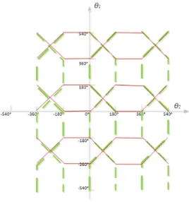
[Fig. 6] shows and , and it can clearly be seen that two edges overlapped in the area.
The simulation was performed with constraints: (1) the L2-GVG was constructed between two obstacles;
(2) the x position of the robot in configuration space was fixed. This is because the configuration space for a robot with fixed x position is essentially a three-dimensional space, and it can easily be seen that an arbitrary configuration can trace the three-way equidistant configuration.
Hence, in our simulation, the L2-GVG edge is one-dimensional, although it has three-way equidistance from obstacles. The simulation result is shown in [Fig. 5].
Fig. 5(a) shows three two-way equidistant faces.
Intersection of the middle transverse face with the upper vertical face gives two L2-GVG edges
and ,as shown in Fig. 5(b).
Fig. 6 Placements of two L2-GVG edges and
,The solid lines represent and the dashed lines represent.
The end point of overlapped edge is a meeting point as a zero-dimensional point in configuration space; in contrast, the overlapped edge is one-dimensional, and the L2-GVG edges then emanate from the end configuration of the overlapped edge where the robot is
able to identify and move in an appropriate direction to construct the L2-GVG edge.
The overlapped edge have never been presented before; they are specific characteristics that so far exist only on the L2-GVG. Obviously, since the connecting point and connecting curve are essential to proper construction of the L2-GVG, it is natural to connect the rod’s four-way equidistant faces.
5. Conclusion
This paper introduces a new GVG-based roadmap for planar two-identical-link robots, called L2-GVG.
This roadmap is defined in terms of workspace distance measurement and therefore can be constructed using only sensor information without prior knowledge of the environment. Nowhere in the process can the robot obtain prior information on the environment except by changing direction at its current position.
This procedure requires a workspace distance function and the gradient lifted into configuration space.
The configuration space of the planar two-identical-link robot is four-dimensional and the L2-GVG edge is one-dimensional. The L2-GVG edge is at the maximum distances from obstacles. It is the safest path for the robot. Because of the higher degrees of freedom of the robot, there are some configurations on L2-GVG edges that have more than one tangent space to the edge, so there are intersections of the L2-GVG edges in configuration space, with corresponding meet configurations and overlap edge.
These are new properties different from those of the point-GVG and rod-GVG.
Using work space distance function and the lifted gradient into configuration space, the robot can systematically generate the L2-GVG, thereby exploring the configuration space of the robot. This is very significant when studying the GVG edges of highly articulated robots. The next step in this line of research is to extend the current work for general two-link robots, operating in the plane.
References
[1] S. R. Ahuja, K. D. Hong, K. S. Hong, "The Rapport Multimedia Conferencing System: A Software Overviews", Proc. of 2nd IEEE Conference on Computer Workstations, pp. 52-58, March, 1988. Choset H, Burdick J. Sensor-based exploration: the hierarchical generalized Voronoi graph. Int J Robotics Res, Vol. 19(2),pp. 6–12 5,2000
DOI: http://dx.doi.org/10.1109/COMWOR.1988.4800 [2] Nagatani K, Choset H. Toward robust sensor based
exploration by constructing reduced generalized Voronoi graph. In: IEEE/RSJ international conference on intelligent robots and systems, Kyongju, Korea, pp. 1687–1692, 1999.
DOI: http://dx.doi.org/10.1109/IROS.1999.811721
[3] Nagatani K, Iwai Y, Tanaka Y. Sensor based navigation for car-like mobile robots using generalized Voronoi. Adv Robotics, Vol, 17(5), pp. 385–401, 2003.
DOI: http://dx.doi.org/10.1163/15685530360663409 [4] Kenneth E Hoff III, John Keyser, Ming Lin, Dinesh
Manocha, and Tim Culver. Fast computation of generalized voronoi diagrams using graphics hardware. In Proceedings of the 26th annual conference on Computer graph- ics and interactive techniques, pp. 277–286, 1999.
[5] Kenneth Hoff III, Tim Culver, John Keyser, Ming C Lin, and Dinesh Manocha. Interactive motion planning using hardware-accelerated com-putation of generalized voronoi diagrams. In Robotics and Automation, Proceedings.
ICRA’00. IEEE International Conference on, Vol. 3, pp.
2931–2937, 2000.
DOI: http://dx.doi.org/10.1109/ROBOT.2000.846473 [6] Charles Pisula, K Hoff, Ming Lin, and Dinesh Manocha.
Randomized path planning for a rigid body based on hardware accelerated voronoi sampling. In Proc.
Workshop on Algorithmic Foundation of Robotics, volume 18. Cite-seer, 2000.
[7] Mark Foskey, Maxim Garber, Ming C Lin, and Dinesh Manocha. A voronoi-based hybrid motion planner. In Intelligent Robots and Systems, Proceedings. IEEE/RSJ International Conference on, vol.1, pp. 55–60, 2001 DOI: http://dx.doi.org/10.1109/IROS.2001.973336
[8] Choset H, Lee JY. Sensor-based construction of a retract-like structure for a planar rod robot. IEEE Trans Robotics Automation, Vol. 17(4), pp. 435–449, 2001.
DOI: http://dx.doi.org/10.1109/70.954756
[9] Lee JY, Choset H. Sensor based planning for rod shaped robots in three dimensions: piece-wise retracts of
R3×S2.IntJ Robotics Res, Vol. 24(5), pp. 343–383, 2005.
DOI: http://dx.doi.org/10.1177/0278364905053687
[10] Lee JY, Choset H. Sensor-based exploration for convex-bodies: a new roadmap for a convex-shaped robot. In: IEEE international conference on robotics and automation, pp. 1675–1682, May 2002.
DOI: http://dx.doi.org/10.1109/ROBOT.2002.1014783
Ming-Lei Shao [Regular member]
•Jul. 2009 : Harbin Institute of Technology Univ., China, BS
•Sep. 2013 ~ current : Guangzhou Institute of Advanced Technology, Chinese Acedemy of Sciences, Research Assistant
•Sep. 2009 ~ current : Hanyang Univ., PhD Candidate.
<Research Interests>
Sensor-based path planning, Generalized Voronoi graph
Kyoo-Sik Shin [Regular member]
•Feb. 1979 : Hanyang Univ., Korea, BS
•Feb. 1987 : Texas at Austin Univ., USA, MS
•Feb. 1995 : Texas at Austin Univ., USA, PhD
•Feb. 2009 ~ current : Hanyang Univ., Dept. of Robot Engineering, Professor
<Research Interests>
Design Optimization of Robot Manipulator, Robot Design Methodology, Energy Efficient Robot System, Hyper- redundant Robot, Gravity-Compensation manipulator.