CONCEPTUAL DESIGN OF CAMERA SYSTEM FOR LUNAR EXPLORATION
HaengPal Heo, YoungSun Kim, JongEuk Park, SangYoun Shin, SangSoon Yong
Korea Aerospace Research Institute
45 Eoeun-Dong, Yuseong-Gu, Daejon 305-333, Korea
,
[email protected],
[email protected],
[email protected],
[email protected]Many countries have been explored the moon and they are still try to understand it for various purposes. Even though the primary goals of the lunar exploration programs are different, most of the spacecraft for lunar exploration have been equipped with a camera system. The spacecraft for lunar exploration may consist of an orbitor and/or a lander and both of them can observe the moon using a camera. In this paper, the conceptual design of camera system for lunar exploration which can be used both in the orbitor and in the lander is introduced. It is an electro-optic camera system that can be used as a push broom manner and as a staring array camera. Therefore, the camera supports switchable function of 1D and 2D observation. 1D and 2D camera have different requirements but they can be implemented in one camera system by using two dimensional image sensor arrays. In order to be functional in different mounting platform, it is designed to have wide span of operational parameters. It is incorporated with zooming mechanism and focusing mechanism and it can also be used as a stereo camera and integration time and frame rate can also be selectable by commands.
KEY WORDS: Manuscripts, Proceedings, Guidelines for Authors, Styleguides, CDROM
1.
INTRODUCTION
The exploration of the Moon had been tried actively at the 1960’s and 1970’s mainly by Russia and USA but not a little country are trying to explore the Moon recently.
SMART-1 was launched by ESA in 2003. SELENE was sent to the moon in 2006 by Japan. Chang’e-1 was launched in 2007 by China and Chandrayan-1 was developed and launched in 2008 by India. The primary goals of these spacecrafts are not the same and many different kinds of payloads are equipped on these spacecraft. Some of them have spectrometers and some of them have scientific instrument to understand the environments of the lunar surroundings. In addition to that, most of the spacecraft for lunar exploration also equipped with a camera system even though the performances of them are not so extreme compared to the camera system for earth observation from LEO (Low Earth Orbit) satellites.
Discussions and researches on the lunar exploration are on going also in Korea nowadays. Considering the fact that the spacecraft developed for lunar exploration, even though it can be a kind of an orbitor or a kind of lander, will need to have a camera system, an electron- optic camera system has been designed conceptually for that purpose. In this paper, conceptual design of the camera system to be installed on the lunar orbitor or lander will be introduced.
2.
REQUIREMENTS
A camera system to be used for lunar exploration has been designed conceptually under the assumption that it could be mounted on a lunar orbitor or a landing system
on the surface of the moon. Because the platform was not fixed, most of the external environments and interfaces of the camera system are defined generally. The design of the camera system itself has been focused on in order to have a capability to build a camera system which is flight worthy as long as the platform is fixed.
Because the first model of the spacecraft for lunar
exploration will have many different kinds of payloads
and it can not be big scale enough to equip with high
performance electro-optic camera system, performance
requirements of the camera system would be a moderate
level. On the contrary, the camera system will be very
compact and will have a few useful functions. For
example, it is designed to support both for one
dimensional observation and two dimensional
observations and it has a compact camera electronics
using a CMOS image sensor. It also has a function to
generate three dimensional images by installing the same
two camera system on the spacecraft. These two cameras
can be operated simultaneously. Because most of people
have curiosity on the Moon, the camera will have
capabilities to take various images on the lunar scenery
under a limited position. To meet this requirement, the
camera system will have a capability to do the zooming-
up and zooming-down. It can be very useful when it is
operated in an orbitor and also when it is operated in the
landing system. Therefore, it can provide pictures with
low resolution and wide field of view and it can also
provide pictures with high resolution and narrow field of
view. Zooming mechanism needs to have focusing
mechanism. Some parts of the optical elements are to be
moved for zooming and some other parts of the optical
elements are to be moved for re-focusing.
The camera system will have on-board image processing capabilities such as non-uniformity correction, pixel rearrangement, image formatting with header information, and real-time image compression. Swath width of the camera system will be about 10km in one dimensional mode before zooming up.
The camera system has capability to keep and manage default mission parameters and they can be updated by command.
3.
SYSTEM DESIGN
The camera system is designed to fulfil the requirements explained in the previous section. The camera system consists of OM (Optical Module) and CEU (Camera Electronic Unit). Several lenses and lens housing builds the OM and it will also have a mechanism for zooming and refocusing. The motors for zooming and refocusing are to be controlled by the camera controller.
Functional block diagram of the camera system is shown in figure 1.
Figure 1. Block Diagram of the Camera System
3.1
Camera System Design
The camera system is designed to have moderate level performance because it will not be the only payload on the spacecraft for lunar exploration. High performance camera system will not be able to be accommodated on such a system because the limitation of the size, weight and power budget which is given to the camera system.
Instead, it will have versatile functional features.
It can be operated in push-broom manner at which the detector will behave just like a linear sensor. It can also be operated in a two dimensional camera mode at which the detector will behave just like an area sensor. The camera system is designed to make it possible to collect three dimensional target images. Two identical cameras will be controlled by a camera controller and a power supply module.
Push broom scanning method is designed to be installed on an orbitor system of the lunar exploration spacecraft. The altitude of the orbitor is assumed to be about 100km on the lunar orbit. The scanning speed and resultant line rate and data rates are calculated on the
orbit altitude. Scanning speed of the lunar surface will be about 1.5km per second. The resolution of the system will be up to a few meters. The resolution and swath width are changeable by command with the help of the zooming mechanism.
In order to be installed on the landing system on the moon, the camera can be designed to be operated in 2D mode. It can provide still images and the frame rate can be about 15 f/s. Zooming mechanism will also work in 2D mode to adjust the field of view and resolution.
Imaging parameters can be adjusted by commands and operating status information will be transmitted via MIL- STD-1553 interface with the spacecraft.
The image data from the detector will be processed, compressed, packetized, and transmitted to the spacecraft in real-time.
3.2
OM Design
It will be dioptrics system and focal length will be about 30cm before zoom-up. Step motor and supporting mechanical gear and housing will be equipped for the zooming and refocusing mechanism. Optical zoom will be up to 5 times and full field of view will be up to 5.6degree. Spectral band will be limited to the visible wavelength. The f number of the system will be big enough to provide good image quality and a rolling shutter operation of the sensor will be implemented in order to increase the sensitivity.
3.3
CEU Design
Camera electronics unit is designed based on the CMOS image sensor in order to be simple and compact.
The CEU consists of FPA (Focal Plane Assembly), CC (Camera Controller), and Power Supply Module.
Figure 2. CEU Configuration
A CMOS sensor will be a core of the FPA and the image data from the CMOS will be processed in the FPA.
Gain and offset control, non-uniformity correction, image compression and formatting are executed in the FPA and the data will be transmitted via wire or wireless communication.
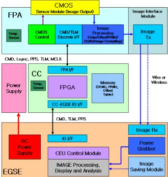
Figure 3. Image Data Transmission
The transmission of the image data via wireless communication is implemented to be tested on the ground model. The FPA is controlled by the CC via serial communication. Imaging parameter will be transmitted and FPA status will be collected on that interface.
Identical two FPAs are controlled by a CC.
Figure 4. Functional Block Diagram of FPA Image data flow from the COMS sensor is shown in the figure 4. The data passes through NUC (Non- Uniformity Correction) function, TDI (Time Delayed Integration) operation, formatting, and compression.
Most of the digital image processing is implemented inside of an FPGA. FPA will also have functions to provide the bias voltages to the CMOS together with the control of the CMOS operation.
Figure 5. Functional Block Diagram of CC
Power supply module will have DC to DC converters to provide voltages to the CC and FPA.
Functional block diagram of the CC (Camera Controller) is shown in figure 5. It has MIL-STD-1553 interface to communicate with the spacecraft. It handles command and telemetry from and to the spacecraft. The CC controls basically two motors which are used for zooming and focusing. Position of the zooming will be pre-programmed inside the CC and the zoom level will be selected by external commands. Depending on the zoom level, precise position of the optical elements is adjusted by the re-focusing mechanism. The refocusing algorithm will be implemented inside the CC.
3.4