TIG-FSW 하이브리드 용접을 이용한 이종재 맞대기 용접부의 온도 분포 특성
방 희 선*․엠,에스,엠조이**,†
*조선대학교 공과대학 선박해양공학과
*조선대학교 대학원 선박해양공학과
Temperature Behavior in Dissimilar Butt Joint During TIG Assisted Friction Stir Welding
HeeSeon Bang* and M.S. Bijoy**,†*Dept. of Naval Architecture and Ocean Engineering, Chosun University, Gwangju 501-759, Korea
**Graduate School, Chosun University, Gwangju 501-759, Korea
†Corresponding author : [email protected]
(Received September 1, 2011 ; Revised October 13, 2011 ; Accepted October 28, 2011)
Abstract
Three-dimensional finite element analysis is performed to study the temperature distribution phenomenon of TIG assisted friction stir welding (TAFSW) between dissimilar plates (Al 6061-T6 and stainless steel 304). TAFSW is a solid-state welding process that integrates TIG (Tungsten Inert Gas) into a friction stir welding (FSW), to preheat the harder material ahead of FSW tool during welding. In order to facilitate the industrial application of welding, 3D numerical modeling of heat transfer has been carried out applying Finite Element Method (FEM). The temperature distribution due to heat generation during TAFSW on dissimilar materials joint is analysed using in-house solver. Moving heat source along with frictional heat between the work specimens and tool surface is considered to calculate the heat input. The analytical model used predicts successfully the maximum welding temperatures that occur on the dissimilar materials during TAFSW. Comparison with the infra red camera and thermocouple measurement results shows that the results from the current numerical simulation have good agreement with the measured data.
Key Words : Friction stir welding, Dissimilar material, Preheating, Heat conduction, Thermocouple, Temperature distribution
1. Introduction
Dissimilar material joints are used in structures where high strength and light weight are desirable. The growing trend for light weight structural designs, especially in automotive, aerospace and ship building has made aluminum alloys to be used as an alternative material and has been reported in literatures1-3). With this new trend of joining aluminum to steels
with required improvements in weld quality has made newer challenges to the manufactures.
Friction stir welding (FSW) offers many potential benefits such as low distortion, improved joint efficiency (tensile strength), improved process robustness, etc., for welding aluminum alloys and these advantages were highlighted in literatures4,5).
Various research works has already been reported about the application of FSW process on dissimilar joining of aluminum alloy to
연 구 논 문
(a)
(b)
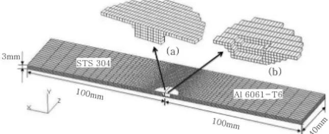
3mm STS 304
Al 6061-T6 100mm
100mm
40mm
Fig. 1 FE model for heat conduction analysis (a) Tool volume (b) Heat input volume around the tool
steel6-9). But equipment rigidity, high force to move the tool and high tool wear rate during FSW induces weld defects. These drawbacks can be overcome by localised preheating the surface of harder material ahead of the rotating tool pin during FSW process. A volume of the material plasticizes during preheating and further to this the welding process can be carried out in the same way as conventional FSW. Kong et al. has demonstrated the use of laser to preheat the workpiece surface ahead of the FSW process10). However, only a narrow portion of the workpiece can be preheated by using laser when compared with TIG arc which allows the preheating over wider area. Also, preheating by TIG arc offers several advantages such as good control over current, absence of spatter, high efficiency and low cost compared to laser.
There are many practical engineering problems that require the study of heat transfer in FSW and many research works have been reported in this area of study11,12). Hwang et al. reported that during FSW, low temperature around the joint line affects the tool pin to traverse the workpiece which results in breakage of pin13). A higher temperature softens the work piece to stick on to the tool leading to exhibit poor microstructure at weld joint. Song and Kovacevic found that preheating on Al 6061-T6 similar butt joint helps to carry out FSW more easily with reduced tool wear14). Kandakar et al. have developed an expression for heat input con- sidering the torque/power obtained from the experiments15). Li et al. proposed the FGM concept to determine thermal stresses using 3D model of Al 6061 and 304L dissimilar joint16). However, to the best knowledge of authors, there has been no report on the heat transfer analysis of dissimilar joints by TAFSW.
Heat conduction analysis on dissimilar joint by TAFSW is important as the thermal histories and the temperature distribution helps in successful implementation of TAFSW to dissimilar materials and further helps in predicting
residual stress, grain sizes and weld strength.
Therefore, this study intends to gain a clear physical insight of thermal history and temperature distribution in dissimilar butt joint between aluminum alloy (Al 6061-T6) and stainless steel 304 (STS 304) using TAFSW.
2. Heat conduction analysis 2.1 Analysis method
For numerical simulation of steady state 3D heat transfer analysis of TAFSW, in-house developed computer program to simulate heat transfer is used with adequate modifications.17) The finite element model for the heat transfer analysis of dissimilar joint for particular tool geometry and material properties (Fig. 1) is developed based on the heat transfer model described in previous work.18) To obtain heat input model, volume of the tool is deducted from the weld nugget zone and the die cavity volume is deducted from extrusion zone. Tool- workpiece contact location in the analysis model is taken same as in experiment. Al 6061- T6 and STS 304 with principal dimension 100mm×40mm×3mm is selected for numerical analysis. A non-uniform mesh with solid brick element has been used for modeling and sufficient fine mesh size is generated at the weld region to get more accurate results. For integration, time step of 1second is adopted.
The boundary conditions of the FE model are taken same as those of the experimental condition. It is assumed that the material is isotropic and the temperature at the boundary
Fig. 2 Schematic drawing of tool and infinitesimal segment area at pin surface
is room temperature. A convective coefficient of 30W-m-2.℃-1 and 25 W-m-2.℃-1 is used for aluminum and stainless steel alloys respectively at top and side surfaces19,20). Temperature dependent material properties such as thermal conductivity, density, coefficient of thermal expansion, specific heat and yield stress for Al 6061-T6 and STS304 are used in this analysis21).
2.2 Governing equation
For the formulation of finite elements of the heat conduction computer program, the governing equation for unstationary state heat conduction is
T Q
t
c T = ∇ =
∂
∂ λ 2
ρ (1)
where, T is temperature (℃), ρ is density (kg-m-3), Q is the rate of temperature change due to heat generation per volume (W-m-3.sec-1), t is time (sec), λ is thermal conductivity of the isotropic material (W-m-1. ℃-1) and c is the specific heat (J-kg-1. ℃-1).
At stainless steel side, the quantity of heat input from the TIG arc is added to the heat input from FSW process based on super position principle. The heat flux for heat input element is calculated by multiplying element volume and uniform heat flux per volume.
Uniform heat flux is obtained by dividing total
heat energy by the product of heat input volume and heating time per unit welding length.
Fig. 2 shows the schematic of FSW tool used in experiment. Rs, R1 and R2 are the radius of tool shoulder, pin top and pin bottom re- spectively. ‘H’ is the height of the pin.
In FSW, the heat energy is generated by friction and deformation process at the interface of the shoulder/workpiece and tool pin/workpiece
19). The total heat generation is given as
Qtotal = Qshoulder + Qpinsurface + Qpinbottom (2)
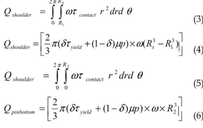
The heat generation from tool shoulder and pin bottom is22,23)
= 2
∫ ∫
π ωτ θ0
2 1
RS
R
contact
shoulder r drd
Q (3)
⎥⎦⎤
⎢⎣⎡ + − × −
= ( (1 ) ) ( )
3
2 3
1
3 R
R p
Qshoulder π δτyield δ μ ω s (4)
= 2∫ ∫π
ωτ θ
0 0
2 R2
contact
shoulder r drd
Q (5)
⎥⎦⎤
⎢⎣⎡ + − × ×
= ( (1 ) ) 23
3
2 p R
Qpinbottom π δτyield δ μ ω
(6) Where, p is the tool pressure (Pa), ω is the tool angular rotation speed (rad/s), µ is the coefficient of friction and δ is the contact slip.
The contact shear stress for sticking condition is τcontact =τyeild =σyeild 3(Pa) and shear stress for slipping condition is τcontact =μp(Pa)24). A uniform contact pressure at tool/work piece interface is assumed in this analysis as detailed contact pressure at this region is unknown. Coefficient of friction is taken as 0.4 and the percentage slip is assumed between 0.1-0.825,26).
To find the heat generated at the pin surface, consider an element of depth ‘dz’ with radius
‘R’ at a height ‘z’ from the pin bottom surface.
From the figure,
H
R
R )
tan ( 1− 2
φ = (7)
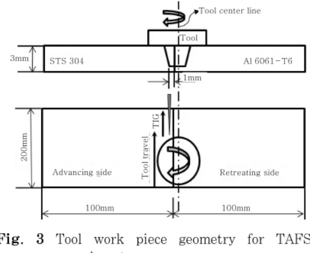
Tool
STS 304 Al 6061-T6
Tool center line
1mm 3mm
200mm
100mm 100mm
Advancing side Tool travel TIG Retreating side
Fig. 3 Tool work piece geometry for TAFSW experiment
R = R
2+ z tan φ
(8)dz Rd
dA= θ , where ‘dA’ is the infinitesimal segmental area.
=2
∫ ∫
π ωτ θ0 0
2 H
contact
pinsurface R d dz
Q (9)
‘
τ
contact’is the uniform contact shear stress at‘dA’.
=2
∫ ∫
π ωτ + φ θ0 0
2
2 tan )
(
H contact
pinsurface R z d dz
Q (10)
⎟⎟⎠
⎜⎜ ⎞
⎝
⎛ + +
= πωτ 2 2 2 φ 3 2φ
2 tan
tan 3
2 H
H R H R
QPinsurface contact
(11) Hence for heat energy generated from the surface of tapered pin is
[ ]
⎥⎦
⎢ ⎤
⎣
⎡ + +
×
×
− +
=
φ φ
ω μ δ δτ
π
3 2 2
2 2
2 tan
tan 3
) ) 1 ( (
2 H H R H R
p
Qpinsurface yield
(12)
When φ= 0, equation (12) gives the heat generation for cylindrical pin surface22).
TIG heat source is used to preheat stainless steel material surface. During preheating, the arc energy from TIG heat source acts on the work piece surface as surface heat source and conducts into the work piece. Gaussian distribution is applied to the heat source and the surface heat flux of arc is given by27)
⎟⎟⎠
⎜⎜ ⎞
⎝
⎛−
=3 2 3 22
) , , (
a a
arc m
r xp r r t VI y x
Q e
π η
(13)
r
2= ( x − w
st )
2+ y
2 (14) η is the arc efficiency, V is the voltage (V), Imis the mean current (A) and ws is the welding speed (mm-s-1) ra is the effective arc radius (mm)28).
Mean current p b
b b p p
m
T T
T I T I I
+
× +
= ×
(15)
Ip pulse current (A) Ib base current (A)
Tp pulse current duration (ms) Tb base current duration (ms)
3. Experiment
Gantry type WINXEN FSW system having maximum load capacity 29.4kN, together with DAIHEN inverter ELECON 500P TIG welding machine was used for TAFSW welding experiment.
To prevent overheating of aluminum and obtain successful weld, pin was offset to the aluminum side just penetrating steel. Dimensions of the dissimilar plates and relative location of tool pin with the butt line are given in Fig. 3.
Tungsten carbide (WC-Co12%) tool having shoulder diameter 18mm, pin top diameter 6.5mm and pin bottom diameter 5.5mm was used in the experiment. TIG leading FSW tool is implemented, where distance between TIG torch and FSW tool was 16mm and applied tool force was 5.5kN. Welding trials were conducted to determine the appropriate welding parameters under various processing conditions. The optimum welding conditions obtained from the experiment is given in Table 1.
The image of the cross-section and top surface of weld obtained with optimised welding condition is shown in Fig. 4. The stirring action took place mainly in the aluminum side because of the tool location with workpiece.
The weld nugget exhibits a classical onion ring
Welding conditions
TIG
Pulse Current/pulsed time Base Current/pulsed time Arc voltage
80A/0.2s 70A/0.5s 26 V
Gas flow rate (Argon) 7 ~ 10 ℓ/min
Arc length 2mm
Electrode angle Dia. of electrode
60°
2.4mm
FSW
Rotation speed 300 rpm
Welding speed 0.8 mm/s
Shoulder dia. Ø18 mm
Top pin dia.
Bottom pin dia.
Ø6.5 mm Ø5.5 mm
Room temperature 20℃
Table 1 Welding condition for TAFSW
Plasticized material- region
Tool Butt line
Fig. 4 Weld cross-section and top bead appearance of dissimilar welded joint by TAFSW
200
STS 304(Advancing side)
85
Butt line End
Start
Al 6061-T6 (Retreating side)
(All dimensions are in mm)
100100
400
350
300
250
200
150
100
50
0
0 50 100 150 200
Time(sec)
Temperature(℃)
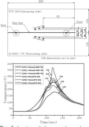
Fig. 5 Location of thermocouples and corres- ponding variation of transient tempera- ture in TAFSW (for optimum welding condition)
Fig. 6 IR camera image showing surface tem- perature during TAFSW
structure on the transverse section of aluminum alloy.
Transient temperatures at mid thickness were recorded at six locations during the TAFSW process using K type thermocouples of 1mm diameter inserted into 1.5mm diameter holes drilled on top side of work specimens (Fig. 5).
Using infrared (IR) camera, instantaneous temperature at the surface of the workpiece during TAFSW process was measured and the temperature field generated is shown in (Fig. 6).
4. Results and discussion
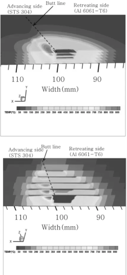
Fig. 7 shows the section plot of transient temperature distribution contour, along the
weld length and thickness, obtained from the three dimensional heat transfer analysis of dissimilar joint by TAFSW. The temperature fields are measured at 2sec after welding, at which the maximum heating temperature occurs.
The temperature contour shown in Fig. 7 is at an approximate depth of 0.2-0.4mm from top surface where maximum temperature distribution is obtained below shoulder. The heat input from TIG heat source calculated
Advancing side (STS 304)
Butt line Retreating side (Al 6061-T6)
110 100 90
Width(mm)
Advancing side (STS 304)
Butt line Retreating side (Al 6061-T6)
110 100 90
Width(mm)
Fig. 7 Temperature contour below shoulder surface along weld length and thickness obtained at 2sec after welding
after 25 seconds is superimposed with heat input by FSW to determine the maximum temperature. Because TIG heat source passes 20mm ahead of FSW tool during welding. The maximum temperature near pin top is attained due to total heat input from TIG heat source and FSW tool. At the region of maximum temperature in STS 304, plastic deformation is expected to be stronger and assumed to extend half the specimen thickness as clearly more visible on bulge part of interface as shown in Fig. 1. This could be because of its plastic state induced primarily by pre-heating tem- perature. The temperature at the butt joint surface of STS 304, which occurred due to frictional heating of tool pin side, makes the material to plastically deform and bond with Aluminium alloy in plastic state. The material deformation driven by the shoulder is more intense in upper thickness of steel face due to
higher preheating temperatures, where the metallurgical and mechanical bonding strength of aluminium with steel is expected to be higher. This in return will enhance material behavior and improve the material bonding without the need of higher torque of FSW.
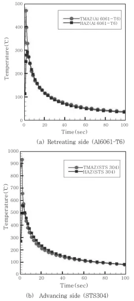
One of the other phenomena observed is during welding, the highest temperature is observed just below the shoulder near stir zone. The maximum simulated temperature at the thermo- mechanically affected zone (TMAZ) in steel occurs at advancing side is about 930℃. In case of aluminum alloy maximum tempera- ture occurs at retreating side and is about 474℃.
Due to reduction in material area below tool pin, more heat is conducted at pin bottom than at pin sidewalls. The temperature near the butt joint surface of the pin bottom comes to around 581℃. Aluminum conducts heat more at this contact region and slightly tends to melt at the butt joint surface. Aluminum alloy is completely made to deform plastically by stirring action of the pin and made to bond with STS 304 which is frictionally heated.
STS304 acts a barrier for aluminum material to flow towards steel during welding and therefore the TMAZ of aluminum is more compared to FSW joints of similar aluminum alloys. Also, the heat flow is found wider towards aluminum due to its high heat conductive characteristic compared to steel. The heat affected zone (HAZ) temperatures are 558℃
and 296℃ for steel and aluminum respectively.
The temperature history at the point of maximum temperature at TMAZ and HAZ in dissimilar joint is shown in Fig. 8. From the figure it can be inferred that due to the lower thermal conductivity and lower specific heat of STS 304, most heat is hold in STS 304 compared to Al 6061-T6.
4.1 Comparison of numerical analysis and experimental result
Numerical simulation results are validated with experimental results obtained through
500
400
300
200
100
0
0 20 40 60 80 100
Time(sec)
Temperature(℃)
TMAZ(Al 6061-T6) HAZ(Al 6061-T6)
(a) Retreating side (Al6061-T6)
1000
900
800
700
600
500
400
300
200
100
0
Temperature(℃)
TMAZ(STS 304) HAZ(STS 304)
0 20 40 60 80 100
Time(sec) (b) Advancing side (STS304)
Fig. 8 Time-Temperature plot for dissimilar joint by TAFSW
400
350
300
250
200
150
100
50
0
Temperature(℃)
0 20 40 60 80 100
Time(sec)
10 30 50 70 90
Al 6061-T6 Experiment FEM
(12mm away from butt line on Al6061)
300
250
200
150
100
50
0
Temperature(℃) STS 304
Experiment FEM
0 20 40 60 80 100
Time(sec)
10 30 50 70 90
(9mm away from butt line on STS 304)
Fig. 9 Comparison of numerically simulated and thermocouple measurement temperature history
infrared camera and thermocouples.
Higher temperature distribution at STS 304 surface is clearly visible from the infrared camera image. This instantaneous surface tem- perature measured on material-tool interface is compared with numerical simulation results (~200℃) and a reasonable match is observed.
The temperature with respect to time obtained from numerical simulation is compared with experimental thermocouple results as shown in Fig. 9. The highest of measured temperatures for steel at 9mm away from butt line and for Aluminum at 12mm away matched very close with the numerical simulation results suppor- ting experimental validation.
5. Conclusion
In this paper, an analytical technique to accurately predict the temperature history of dissimilar (Al 6061-T6 and STS 304) butt welded joint by TIG assisted FSW have been successfully established. The aluminium alloy is stirred to a plastic state and made to weld with stainless steel alloy which is frictionally heated by tool pin side. In addition, because of its plastic state induced primarily by TIG pre-heating temperature on STS304 surface, plastic deformation at joint surface is expected to be stronger and assumed to extend half the specimen thickness during welding. The maximum
temperatures predicted from numerical simulation, 2 seconds after welding, in STS and Al 6061 were 930℃ and 474℃ respectively. This enhances Al 6061 to create a sufficiently strong metallurgical bond with STS304. Aluminum conducts heat more and slightly tends to melt at the bottom of faying surface. Also, com- plemented advantage of preheating eases out the process of FSW reducing the required torque due to lower friction. Furthermore, very good agreement between the simulated and measured temperature shows the credibility of the heat conduction model used and developed, potentially providing inputs for various simulations, such as residual stress formation mechanism and distortion of the weldment. With this numerical model established, results can be taken into various cases of temperature predictions in dissimilar materials, predominantly for steel to aluminum joints.
Acknowledgement
This study was supported by research fund from Chosun University, 2010
References
1. Scott Brown: Feasibility of Replacing Structural Steel with Aluminum Alloys in the Shipbuilding Industry;(1999), http://tc.engr.wisc.edu/uer/uer99/
author1/index.html
2. M. P. Miles, T. W. Nelson and D. W. Melton:
Formability of friction stir welded dissimilar aluminum alloy sheets, Metall. Mater. Trans. A 36A (2005), 3335-3342
3. W.B.Lee, M. Schmuecker, U.A. Mercardo, G.Biallas and S.B. Jung: Interface reaction in steel-aluminum joints made by friction stir welding, Scripta Mater.
55 (2006), 355-358
4. Dawes, C.J and Thomas W.M: Friction Stir Process Welds Aluminum alloys, Weld. J. 75 (1996), 41-46.
5. R.S.Misra and Z.Y.Ma: Friction Stir Welding and Processing, Mater. Sci. Eng. R 50 (2005), 1-78 6. H.Uzun, C.D.Donne and A.Argagnotto: Friction stir
welding of dissimilar. Al 6013-T4 To X5CrNi18-10 Stainless Steel, Mater. Design 26 (2005), 41-46 7. Thaiping Chen: Process parameters study on FSW
joint of dissimilar metals for aluminum-steel, J Mater Sci 44 (2009), 2573-2580
8. H. Okamura and K. Aota: Joining of dissimilar materials with friction stir welding, Weld Int, 11 (2004), 852-860
9. W.H.Jiang and R.Kovacevic: Feasibility study of friction stir welding of 6061-T6 aluminium alloy with AISI 1018 steel, J. Eng Manuf. 10 (2004), 1323-1331 10. G.Kohn, Y.Greenberg, I.Makover and A.Munitz:
Laser-assisted friction stir welding, Welding J 81 (2002), 46-48
11. Vijay Soundararajan, Srdja Zekovic, and Radovan Kovacevic: Thermo-mechanical model with adaptive boundary conditions for friction stir welding of Al 6061, Int J Mach Tools Manuf 45 (2005), 1577-1587 12. C. Hamilton, S. Dymek and A. Sommers: A
thermal model of friction stir welding in aluminum alloys, Int J Mach Tools Manuf 48 (2008), 1120-1130 13. Y.M. Hwang, Z.W. Kang, Y.C. Chiou and H.H.Hsu:
Experimental study on temperature distributions within the workpiece during friction stir welding of aluminum alloys, Int J Mach Tools Manuf 48 (2008), 778-787
14. M.Song and R.Kovacevic: Thermal modeling of friction stir welding in a moving coordinate system and its validation, Int J Mach Tools Manuf 43 (2003), 605-615
15. M.Z.H Khandkar, J.A.Khan and A.P.Reynolds:
Prediction of temperature distribution and thermal history during friction stir welding: input torque based model, Sci Tech Weld Join 8 (2003), 165-174 16. K. Li, D. Aidun and P. Marzocca: 3-D Thermo-
Mechanical Analysis of Friction Stir Welding of Dissimilar Metals Using Functionally Graded Material Concept: Trends in Welding Research, Proceedings of the 8th International Conference, Georgia, USA, (2008), 726-730
17. Ueda.Y, Kim.Y.C, Yamakita.T and Bang.H.S:
Applicability of substituting plane deformation problems for three dimensional thermal elasto-plastic problems, J Jpn Weld Soc 6 (1988), 47-53
18. S.R. Rajesh, H.S. Bang, H.J. Kim and H.S. Bang:
Analysis of complex heat flow phenomena with friction stir welding using 3D-analytical model, Adv. Mater Res, (2007), 339-344
19. Chao.Y.J and Qi.X: Thermal and Thermomechanical Modeling of Friction Stir Welding of Aluminum Alloy 6061-T6, J Mater Proc. Manuf Sci 7 (1998), 215-233
20. P. Cavaliere, V.Dattoma and F.W.Panella: Numerical analysis of multipoint CDW welding process on stainless AISI304 steel bars, Compu Mater Sci 46, (2009), 1109-1118
21. JAHM Material Properties Database, JAHM Software, (2003), Inc,USA
22. H. Schmidt, J. Hattel and J. West: An analytical model for the heat generation in friction stir welding, 23. Model Simul Mater Sci Eng (2004), 143-157
23. H. Schmidt and JH. Hattel, Modelling the heat flow around tool probe in friction stir welding, Sci Technol Weld Join 10 (2005), 176-186
24. J.H.Hattel, H.N.B Schmidt and C.Tutum: Thermo mechanical Modelling of Friction Stir Welding:
Trends in Welding Research, in: Proceedings of the 8th International Conference, Georgia, USA., (2008), 1-10
25. R. Nandan, G. G. Roy and T. DebRoy: Numerical Simulation of Three Dimensional Heat Transfer and Plastic Flow During Friction Stir Welding, Metal.
Mater. Trans. A 37 (2006), 1247-1259
26. R. Nandan, G. G. Roy, T. J. Lienert and T.
DebRoy: Numerical modelling of 3D plastic flow and heat transfer during friction stir welding of stainless steel, Sci. Technol. Weld. Joining 11 (2006), 526-537
27. Y Chen, L Li, J Fang and X Feng: Numerical Analysis of Energy Effect in Laser-TIG Hybrid Welding, J Mater Sci Tech 19 (2003), 23-26 28. P. K. Giridharan and N. Murugan, Optimization of
pulsed GTA welding process parameters, Int J Adv Manuf Technol 40 (2009), 478-489