TIG-FSW 하이브리드 용접을 이용한 이종재 맞대기 용접부의 잔류응력 해석
방희선*․노찬승**,†․엠 에스 비조이***․방한서*․이윤기****
*조선대학교 공과대학 선박해양공학과
**조선이공대학 선박해양기계과
***한국선급 해사연구팀
****조선이공대학 자동차과
Analysis of Residual Stress on Dissimilar Butt Joint by TIG Assisted Hybrid Friction Stir Welding
Bang Hee-Seon*, Ro Chan-Seoung**,†, M.S. Bijoy***, Bang Han-Sur* and Lee Yoon-Ki****
*Dept. of Naval Architechture & Ocean Engineering, Chosun University, Gwangju 500-040, Korea
**Dept. of Naval Architechture & Mechanics, Chosun College of Science & Tech., Gwangju 501-744, Korea
***Maritime Technology Research Team, Korean Register(KR), Daejeon 305-343, Korea
****Dept. of Automobile, Chosun College of Science & Technology, Gwangju 501-744, Korea
†Corresponding author : [email protected]
(Received November 9, 2011 ; Revised December 22, 2011 ; Accepted April 30, 2012)
Abstract
This paper aimed to study and understand the mechanical phenomena of thermal elasto-plastic behavior on the dissimilar butt joint (Al 6061-T6 and STS304) by TIG assisted Friction Stir Welding. Heat conduction and residual stress analysis is carried out using in-house solver. Two-dimensional results of the heat distribution and residual stresses in dissimilar joint for particular tool geometry and material properties are presented. The predicted stress along longitudinal direction in Al 6061-T6 and STS304 are approximately between 12-15% of their respective yield strengths. A comparison is made between experimentally measured and numerically predicted equivalent residual stress values.
Key Words : Friction stir welding, Dissimilar material, Heat conduction, Residual stress, strain gauge
1. Introduction
A reliable method to join dissimilar materials would make it possible to make these joints in several applications such as in automobiles, aerospace, shipbuilding and so on. Friction stir welding (FSW) patented by W. Thomas and his colleagues of The Welding Institute (TWI), UK, in 1991 is an innovative joining process which can weld dissimilar alloys traditionally considered
unweldable1-3). When joining dissimilar materials, especially aluminum alloy to steel, the residual stresses produced are expected to be severe due to the frictional work and plastic de- formation during FSW. The restraints exerted by rigid clamping used in FSW impede the contraction of the weld nugget and heat affected zone during cooling, thereby resulting in generation of residual stresses4). Therefore, to establish the quality and reliability of the welded structure, it is necessary to clarify the
연 구 논 문
mechanical behaviour of welded joint in advance in design stage. In the recent past several studies have been carried out on the measurement of residual stresses in FSW, but most of the work is focused on similar weld joint of either aluminum alloys or steel joints5-9). However to the best knowledge of authors, there has been no previous reports on the residual stress analysis of dissimilar joints by TIG assisted FSW (TAFSW). TAFSW is a solid-state welding process that utilizes TIG (Tungsten Inert Gas) electrode to preheat harder material surface during FSW, which in turn will significantly reduce tool wear allowing faster welding speeds. Also, residual stress distribution in steel-aluminum joint is incomparable with previous work as the temperature distribution is non-uniform due to thermal properties of entirely different materials. In order to predict the residual stress in Aluminum 6061-T6 (Al 6061-T6) and Stainless steel 304 (STS304) butt joint by TAFSW, two dimensional (2D) thermal elasto-plastic analysis is carried out.
In-house developed computer program with adequate modifications is used to simulate heat conduction and thermal elasto-plastic analysis10). Numerical simulation by finite element method has been applied actively to clarify and compare the mechanical characteristics and production mechanism of residual stresses. Results from the experiment have been compared and examined with numerical analysis.
2. Thermal elasto-plastic analysis 2.1 Theoretical background for thermal elasto-
plastic FE analysis
For the formulation of finite elements of the thermal elasto-plastic computer program, the governing equation for unstationary state heat conduction when the material is isotropic and at a continuum is11)
t T Q
c T = ∇ =
∂
∂ 2
λ
ρ (1)
where, T is temperature (0C), ρ is density (kg-m-3), Q is rate of temperature change due to heat generation per volume (W-m-3.sec-1), t is time (sec), λ is thermal conductivity of isotropic material (W-m-1.0C-1) and c is specific heat (J-kg-1.0C-1).
For residual stress analysis, increment of strain based on plastic flow theory is adopted in the plastic region12).
Total strain is the summation of elastic, plastic and thermal strains and is given by
ε = ε
e+ ε
p+ ε
t (2)By principle of virtual work, the relationship between the increment of the nodal force, and the nodal displacement, , is given by
{ dF } = [ K ]{ dw } − { dL }
(3) Where stiffness matrix,∫
= B D d dV
K] [ ]T[ ]{ }
[ ε (4)
and nodal force due to initial strain,
{dL}=
∫
[B]T[C]dTdV (5) Total strain increment is{dε}={dεe}+{dεp}+{dεT} (6) where, is the increment of elastic strain,
is the increment of plastic strain an is the increment of thermal expansion strain.
The total increment of stress is
T dT
D D D f
d D d
e e
e
e ⎟⎟⎠
⎜⎜ ⎞
⎝
⎛
∂ +∂
⎭−
⎬⎫
⎩⎨
⎧
∂
− ∂
= [ ]− { }
} { ] [ ]
[ } ]{
[ } {
1 σ σ α
λ ε
σ
(7) where [De]is the elasticity matrix, ‘λ’ is thermal conductivity and ‘α’ is the coefficient of linear expansion.
Using this formulation, specialized finite element codes have been developed to analyse the residual stress characteristics in dissimilar weld joint.
100mm 100mm
Retreating side Advancing side
Tool travelTIG 200mm
3mm STS 304 Al 6061-T6
Tool center
Tool Coarse mesh at weld zone
Butt line Heat input model
Tool model
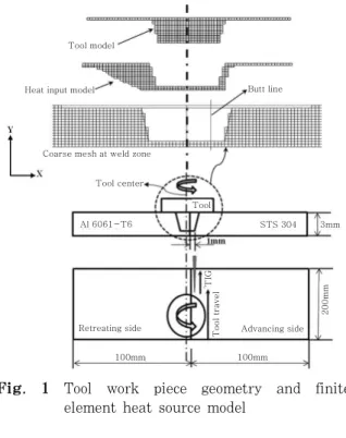
Fig. 1 Tool work piece geometry and finite element heat source model
3. Analysis method and FE Model
The 2D heat input model for finite element analysis of dissimilar joint for particular tool geometry and material properties (Fig. 1) is developed based on the heat transfer model described in previous work13). To obtain heat input model, volume of the tool is deducted from the weld nugget zone and the die cavity volume is deducted from extrusion zone. The calculated heat energy is input in to this heat input model in order to determine the heat conduction characteristics. Initially thermal analysis for dissimilar butt joint by TAFSW is carried out using 2D finite element model with temperature dependent material properties.
The computed temperature history in each node from the thermal analysis is input as body load to determine residual stress distribution. The change in material properties (heat conductivity, specific heat, density, heat expansion coefficients, etc.) with respect to temperature is considered in the calculations throughout the analysis14). The residual stress characteristics during welding is predicted using fully constrained boundary condition taken similar to the experimental condition. The boundary condition of specimen
after welding (fixture release) was considered with free expansion and shrinkage and having the same mechanical restraint condition with actual weld structure. The heat flux for heat input element is calculated by multiplying element volume and uniform heat flux per volume.
Uniform heat flux is obtained by dividing total heat energy by the product of heat input volume and heating time per unit welding length.
The heat input to the model is calculated from the analytical equations of heat generation due to friction between tool and work piece, which is presented in authors previous work15).
The total heat generation for partial sliding/
sticking condition at the tool/matrix interface is given as18)
Qtotal = Qshoulder +Qpinsurface + Qpinbottom (8) where,
⎥⎦
⎢⎣ ⎤
⎡ + − × −
= ( (1 ) ) ( )
3
2 3
1
3 R
R p
Qshoulder π δτyield δ μ ω s
(9)
⎥
⎥⎥
⎦
⎤
⎢⎢
⎢
⎣
⎡
⎟⎟⎠
⎜⎜ ⎞
⎝
⎛ + +
×
×
− +
= φ φ
ω μ δ δτ
π
3 2 2
2 2
2 tan
tan 3 ) ) 1 ( ( 2
H H R H R
p Q
yield
pinsurface
(10)
⎥⎦
⎢⎣ ⎤
⎡ + − × ×
= ( (1 ) ) 23
3
2 p R
Qpinbottom π δτyield δ μ ω
(11) p is the tool pressure (Pa), ω is the tool angular rotation speed (rad/s), µ is the coefficient of friction and δ is the contact slip.
The contact shear stress for sticking condition is (Pa) and shear stress for slipping condition is (Pa). Rs, R1
and R2 are the radius of tool shoulder, pin top and pin bottom respectively. ‘H’ is the height of the pin.
H
R
R )
tan
φ
= ( 1− 2 (12)Gaussian distribution is applied to the heat source and the surface heat flux of arc is given by16)
FSW
Rotation speed Welding speed
Shoulder diameter of tool Top pin diameter of tool Bottom pin diameter of tool Room temperature
300 rpm 0.8 mm/s Ø18 mm Ø6.5 mm Ø5.5 mm 20°C
TIG
Pulse Current/pulsed time Base Current/pulsed time Arc voltage
Gas flow rate (Argon) Arc length
Electrode angle Dia. of electrode
80A/0.2s 70A/0.5s 26V 7~10ℓ/min 2mm 60°
2.4mm Table 2 Welding condition for TAFSW
TEMP(℃)
Thickness(mm)
50 100 150 200 250 300 350 400 450 500 550 600 650 700 750 800 850 Width(mm)
85 90 95 100 105 110 115
Advancing side STS 304 Butt line
Retreating side Al 6061-T6 6
4 2 0 -2
Fig. 3 Temperature contour obtained at 2sec for dissimilar butt joint
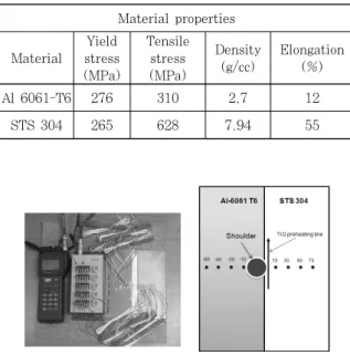
Material properties
Material
Yield stress (MPa)
Tensile stress (MPa)
Density (g/cc)
Elongation (%)
Al 6061-T6 276 310 2.7 12
STS 304 265 628 7.94 55
Fig. 2 Residual stress measurement and location of strain gauges
Table 1 Mechanical properties of base materials
⎟⎟⎠
⎞
⎜⎜⎝
⎛−
= 2
2
2 3
) 3 , , (
a a
m
arc r
xp r r t VI y x
Q e
π η
(13) r2=(x−wst)2+y2 (14) η is the arc efficiency, V is the voltage (V), Im
is the mean current (A) and ws is the welding speed (mm-s-1) ra is the effective arc radius (mm).17)
Mean current p b
b b p p
m T T
T I T I I
+
× +
= ×
(15)
Where Ip is the pulse current (A), Ib is the base current (A), Tp is the pulse current duration (ms) and Tb is the base current duration (ms).
4. Experiment
Gantry type FSW system having maximum load capacity 29.4kN, together with TIG welding machine was used for TAFSW welding experiment. To carry out TAFSW experiment of dissimilar materials, TIG electrode leading FSW tool was implemented. The mechanical properties of the base materials are given in Table 1. The optimum welding conditions and tool dimensions are given in Table 2. In order
to establish the feasibility of numerical analysis, welding residual stress by numerical simulation has been compared with experimentally measured welding residual stress of weldment using strain gauges.
5. Results and discussion 5.1 Thermal analysis
Fig. 3 shows the 2D section plot of transient temperature distribution contour obtained from heat transfer analysis of dissimilar joint by TAFSW. The temperature fields are measured at 2sec after welding, at which the maximum heating temperature occurred. The heat flux is calculated independently for FSW and TIG arc and superimposed to determine temperature distribution. To prevent overheating of aluminum and obtain successful weld, pin position was offset to the aluminum side just penetrating steel. The heat flow is found wider towards aluminum due to its high heat conductive characteristic compared to steel. At the region of maximum temperature in STS 304, plastic
Stress(MPa) 30
20
10
0
-10
-20 -40 -20 0 20 40
Distance from weld center line(mm)
‘
-40 -20 0 20 40
Distance from weld center line(mm)
Stress(MPa)
50 40
30 20 10
0 -10 -20 -30
(a) Transverse residual stresses (σx) at 0.2mm and 1.4mm below top surface
80
60
40
20
0
-20
-40
Stress(MPa)
-40 -20 0 20 40
Distance from weld center line(mm)
80
60
40
20
0
-20
-40
Stress(MPa)
-40 -20 0 20 40
Distance from weld center line(mm) (b) Longitudinal residual stresses (σz) at 0.2mm and 1.4mm below top surface Fig. 4 Residual stress characteristics in dissimilar joint by numerical analysis deformation is expected to be stronger because
its plastic state induced primarily by pre- heating temperature from TIG electrode.
5.2 Residual stress analysis
Transverse (σx) and longitudinal (σz) residual stress characteristics of dissimilar joint along width) have been investigated from 2D elasto- plastic analysis. Both condition of with clamp fixing and clam release at distances 0.2 mm and 1.4mm below top surface are shown in Fig 4. These measurement distances are chosen because the maximum heat is conducted at the upper half thickness of the specimen.
From the results, the residual stress distribution is observed asymmetric with respect to the weld axis and the residual stresses are found to be altered on releasing the fixtures after TAFSW. A zigzag type residual stress distribution is observed. This is because, during TAFSW,
the thermal expansion of the material is expected to be nonlinear as it is restricted by the external tool force. Generally, longitudinal residual stresses showed both compressive and tensile at mid regions near the tool shoulder edge of at Al 6061 and STS304. There is an increase in stress values after cooling when the fixture is released. The stress distribution is tensile in longitudinal and transverse direction away from tool shoulder edge towards base materials.
Peak value in longitudinal stress is lower in the STS304 side than that in aluminum alloy side. This is because the stirring action took place mainly in the aluminium side because of the tool location with work piece and steel alloys acts as a barrier for aluminium alloy to flow towards steel side during welding. The residual stress at aluminum side is therefore subjected to tensile stresses along certain distance and then becomes compressive. The maximum
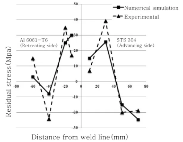
Distance from weld line(mm)
Residual stress(Mpa)
Numerical simulation Experimental
STS 304 (Advancing side) Al 6061-T6
(Retreating side)
Fig. 5 Comparison of numerically simulated equivalent residual stress with experi- mental result
predicted longitudinal stress values are approximately 15% of their respective base material yield strengths. The rise in residual stress is about 20-35% after the clamping is released in both advancing and retreating sides.
The residual stress at top surface obtained from strain gauge measurement have been compare with equivalent residual stress obtained from numerical simulation (Fig. 5). The small difference in residual stress distribution obtained from numerical simulation and the experiment might be attributed to variation in ideal and experimental case (variation in thermally induced stress in Al6061-STS304 joint, variation in tool pressure acting on work piece having different hardness) or due to measurement errors.
6. Conclusion
The residual stress distribution in dissimilar Stainless steel 304 (STS304) and Aluminum 6061-T6 (Al 6061-T6) butt joint by TAFSW has been predicted. Based on the thermal history obtained from the heat transfer analysis 2D finite element elastic-plastic residual stress analysis has been carried out and the predicted values were confirmed with experimental measurement data. During welding, heat is generated throughout a broad region having the width of the tool shoulder diameter. Therefore
the residual stress produced was asymmetrical due to the asymmetry in the plasticized material volume along the advancing and retreating side of the stir zone that generated the heat. It can be inferred that the difference in material properties is responsible for the unsymmetrical distribution of residual stresses.
The sign of longitudinal residual stresses were tensile in nature near stir zone.
Acknowledgement
Following are results of a study on the "Human Resource Development Center for Econonic Region Leading Industry" Project, supported by the Ministry of Education, Science & Technology (MEST) and the National Research Foundation of Korea(NRF).
References
1. C. M. Chen and R. Kovacevic, Finite element modeling of friction stir welding-thermal and thermomechanical analysis, Int J of Mach Tools and Manuf, Vol 43, Issue 13, (2003), 1319-1326
2. M.J. Peel, A. Steuwer, P.J. Withers, T. Dickerson, Q. Shi, and H. Shercliff, Dissimilar Friction Stir Welds in AA5083-AA6082. Part I: Process Parameter Effects on Thermal History and Weld Properties, Metall Mater Trans A, Vol 37A, (2006), 2183-2193 3. M. Czechowski, Low-cycle fatigue of friction stir
welded Al-Mg alloys, J Mater Process Technol, 164-165 (2005), 1001-1006
4. R.S.Misra, Z.Y.Ma, Friction stir welding and processing, Mater Sci Eng R 50 (2005), 1-78
5. C. Dalle Donne, E. Lima, J. Wegener, A. Pyzalla, and T. Buslaps, “Investigation of residual stresses in friction stir welds”, in Third international symposium on friction stir welding (Kobe, Japan), TWI, Cambridge, 2001
6. Peel M, Steuwer A, Preuss M, Withers PJ.
Microstructure, mechanical properties and residual stresses as a function of welding speed in aluminium AA5083 friction stir welds. Acta Materialia, 51(16) (2003), 4791-4801
7. V. Dattoma, M. De Giorgi and R. Nobile, On the Residual Stress Field in the Aluminium Alloy FSW Joints, Strain, 45 (2009), 380-386
8. A. P. Reynolds, W. Tang, T. Gnaupel-Herold, and P.
H., “Structure, properties and residual stress of 304L stainless steel friction stir welds”, Scr. Mater.
48-9 (2003), 1289-1294
9. Chao YJ, Qi X, Teng W. Heat transfer in friction
stir welding. Experimental and numerical studies.
Transaction of the ASME, 105 (2003)138-145 10. Ueda.Y, Kim.Y.C, Yamakita.T and Bang.H.S:
Applicability of substituting plane deformation problems for three dimensional thermal elasto-plastic problems, J Jpn Weld Soc 6 (1988), 47-53
11. J.P.Holman, Heat tranfer, McGraw-Hill, (1986) 12. Ueda J, Wang J, Murakawa H, Juan M.G., Three
Dimensional Numerical Simulation of Various Thermo-Mechanical Processes by FEM (Report I),Trans. of JWRI, 21-2, (1992) 111-117
13. Rajesh, S.R., Bang, H.S., Kim, H.J., and Bang, H.S., Analysis of complex heat flow phenomena with friction stir welding using 3D-analytical model, Advanced Materials Research, (2007) 339-344
14. JAHM Material Properties Database, JAHM Software, (2003), Inc,USA
15. Hee Seon Bang, M.S.Bijoy, Temperature Behavior in Dissimilar Butt Join During TIG Assisted Friction Stir Welding, submitted for publication, KWJS 16. Y Chen, L Li, J Fang and X Feng: Numerical
Analysis of Energy Effect in Laser-TIG Hybrid Welding, J Mater Sci Tech 19 (2003), 23-26 17. P. K. Giridharan and N. Murugan, Optimization of
pulsed GTA welding process parameters, Int J Adv Manuf Technol 40 (2009), 478-489
18. H.Schmidt, J.hattel and J.West: An analytical model for the heat generation in friction stri welding, 23. Model Simul Mater Sci Eng (2004), 143-157