1. 서 론
자동차 연비규제 및 차세대 전지기반 자동차의 도입 에 따라 점차 경량화된 자동차 차체가 요구되고 있다.
자동차 경량화를 위한 적극적으로 도입 및 검토되는 소 재는 초고강도강, 알루미늄, 마그네슘, 복합재료 등이 있다. 이들 다양한 소재가 복합적으로 적용되면서 소위 MMI (Multi-Material Integration) 혹은 MMLV (Multi- Material Lightweight Vehicle)의 개념이 소개되고 있다. 다양한 소재가 복합적으로 적용되기 위해 가장 중요한 요소기술의 하나는 소재나 부품간 조립을 위한 접합기술이다. 그 중에서도 특히 알루미늄합금과 강판
의 이종재료조합은 가장 빈도가 높은 소재조합이다. 알 루미늄합금과 강판의 용접의 경우 다양한 기법이 소개 되었으며
1,2), 용융용접을 이용할 때는 입열을 줄이기 위 해 레이저나 단락모드의 아크용접기법의 적용이 검토되 었다
3-5).
알루미늄합금과 강판의 경우 녹는점, 열전도도 등의 차이가 있으며 금속간 화합물의 존재로 인해 용융용접 에 비해 마찰교반용접 (Friction Stir Welding, FSW) 의 적용이 보다 용이한 소재의 조합이다. 자동차 차체의 경우 주로 저항점용접이 사용되고 있는데 Al/Fe 이종재 료 조합에서 마찰교반점용접(Friction Stir Spot Welding, FSSW)이 대체공정으로 제안되어 다양한 소재의 조합 과 공정변수에 따른 용접특성에 대해 연구되었다
6-14).
툴 경로제어를 이용한 Al/Fe 이종금속 마찰교반점용접 공정특성 평가
윤 진 영*,**․김 철 희*,†․이 세 헌**
*
한국생산기술연구원 용접접합그룹
**
한양대학교 기계공학부
Effect of Circumferential Tool Path Control on Friction Stir Spot Welding of Al/Fe Dissimilar Metal Joint
Jin Young Yoon*
,
**, Cheolhee Kim*,
† and Sehun Rhee***Joining R&D Group, KITECH, Incheon 21999, Korea
**School of Mechanical Engineering, Hanyang University, Seoul 04763, Korea
†Corresponding author : [email protected]
(Received May 9, 2016 ; Revised May 31, 2016 ; Accepted June 8, 2016)
Abstract
Joining Al/Fe dissimilar metals is becoming a subject of special interest in the assembly of automotive parts as a trade-off between the weight lightening and the cost reduction. Although various studies have been introduced to join Al alloy with the steel sheet by fusion welding, weak joint strength and galvanic corrosion still remained as problems to be solved. As a solid state welding, friction stir welding has been preferred to fusion welding processes in the dissimilar metal joints.
This study investigated friction stir spot welding (FSSW) of Al alloy to the thin steel sheet with a thickness of 0.65 mm. The conventional FSSW is a stationary spot welding process but new approach adopted an additional circumferential movement in company with high speed tool rotation. A full factorial experimental design was implemented, and the main and interaction effects of parameters were analysed on the failure load in the tensile shear test. The direction and radius of rotation were statistically significant parameters and these two parameters affected the joint width and the shape of the hook.
Key Words : Dissimilar metal, Al/Fe, Friction stir spot welding, Tool path, Experimental design
ISSN 2466-2232
Online ISSN 2466-2100
특히 공정 후 키싱 본드(kissing bond)
15)와 유사하 게 계면 사이에 산화막이 잔존하여 발생하는 결함인 후 크(hook)의 형성 및 그 형상과 용접강도간의 상관관계 에 대해서 많은 연구가 진행되었다
16-18). 후크의 안쪽에 서는 충분한 금속간 접합이 이루어지나 바깥쪽에서는 부분적 금속간 접합 및 미접합이 발생하므로 전단 강도 를 전달하기 위해서는 낮은 후크의 높이와 넓은 후크간 너비가 선호된다. 대부분의 마찰교반점용접공정에서 알 루미늄을 상판에 배치하고 하판에 위치한 강판 상면의 일부까지 툴을 삽입하기 때문에 박판의 용접에서 접합 강도 확보가 비교적 어렵다. 선행 연구들에서 다양한 공정변수의 영향을 평가하였으나 보다 적극적으로 접합 강도를 향상시키기 해서는 툴 경로제어
19,20)나 다양한 툴 형상
21-25)의 고려가 가능하다.
본 연구에서는 교반을 위해 회전하는 툴을 원형의 경 로로 이송하는 방식
20)의 마찰교반점용접을 채택하고 실 험계획법을 이용하여 공정변수가 용접부 형상과 인장강 도에 미치는 영향을 검토하고자 하였다.
2. 실험장치 및 방법
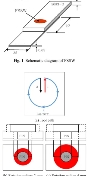
본 연구에 사용된 알루미늄 소재는 5083-O재이고 철강소재는 270 MPa급 인장강도를 가지는 자동차용 무 도금 소재이다. 각 소재의 화학적 기계적 물성치는 Table 1과 2에 표시하였으며 두께는 각각 3.0 mm, 0.65 mm 이다. 실험방법은 Fig. 1과 같이 알루미늄 소재를 상판에
위치시키고 철강소재를 하판에 위치시켰다. 소재의 겹침 길이는 40 mm로 설정하였으며 겹침부의 중심에서 FSSW 를 실시하였다. 시편은 겹침부의 양끝에서 볼트 체결식 가압 지그를 사용하여 고정하였다.
Fig. 2에 도시된 바와 같이 툴이 회전하는 상태에서 삽입 후 일정한 회전 반경으로 원주운동을 실시하였다.
중심에서 삽입된 툴이 원주상으로 이동한 후 원주를 따 라 일정 속도로 이송되고 다시 중심으로 복귀하는 공정 으로 진행하였다. 용접툴의 소재는 WC-Co 12 %이며, 툴 의 형상은 Fig. 3과 같다.
실험계획의 변수는 툴 회전방향, 툴 이송 경로반경, 툴 회전속도 및 이송속도로 선정하였으며, 각 변수의 수준 은 Table. 3에 표시하였다.
완전요인 실험설계를 하였으며 각 실험조건의 조합은 총 36회이다. 시험편은 전단인장시험을 실시하여 파단
Chemical composition
(wt. %)
Si Fe Cu Mn Mg Cr
0.083 0.297 0.02 0.655 4.402 0.096
Zn Ti Al
0.002 0.01 Bal.
Mechanical property
Ultimate strength(N/mm
2)
Yield strength (N/mm
2)
Elongation (%)
316 143 23.15
Table 2 Chemical composition and mechanical properties
of steel sheet usedChemical composition
(wt. %)
C Si Mn P S Al Fe
0.0011 0.003 0.078 0.009 0.005 0.051 Bal.
Mechanical property
Ultimate strength (N/mm
2)
Yield strength (N/mm
2)
Elongation (%)
284 136 50
Table 1 Chemical composition and mechanical properties
of Al 5083-O alloy used35 0.65
40 5083-O Unit:mm 3.0
FSSW
Fig. 1 Schematic diagram of FSSW
3 1
2 Top view
(a) Tool path
PIN PIN
PIN PIN
(b) Rotation radius: 2 mm (c) Rotation radius: 4 mm
Fig. 2 Tool path and joining area
하중을 3회 측정하였다. 각 시험편에 대해서는 단면절 단 후 현미경으로 단면형상을 관찰하였다.
3. 실험결과
3.1 파단 하중에 대한 인자요인분석
통계 분석소프트웨어인 미니탭으로 주효과와 2인자 교 호작용에 대한 분산분석(Analysis of Variance, ANOVA) 을 실시한 결과를 Table 4에 나타내었다. 유의 수준 α=
0.05에서 유의한 인자는 회전방향과 툴 이송 경로반경 으로 확인되었다.
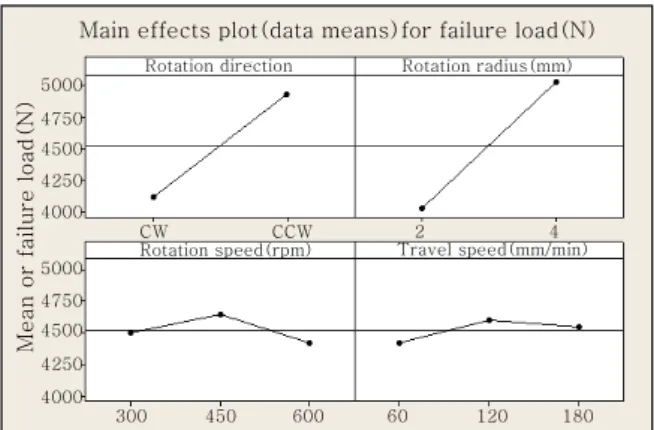
Fig. 4는 인자별 주효과를 도시한 그림이다. 회전방 향의 경우 CCW일 경우에 파단하중이 크게 나타났으며 툴 이송 경로반경이 커질수록 파단하중이 크게 측정되 었다. Fig. 5에서와 같이 파단하중은 회전방향 CCW, 툴 이송 경로반경 4 mm에서 가장 크다. 두 인자에서 파단하 중의 차이가 발생하는 원인에 대해서는 다음 절들에서 자세히 고찰하였다.
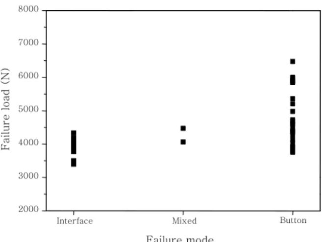
전단인장시험에서 파단모드는 버튼파단, 계면 파단 혹 은 혼합파단으로 구분하였다. 이 때 혼합파단은 3번의 인장시험에서 버튼파단과 계면파단이 모두 존재하는 모 드이다. Fig. 6는 파단하중과 파단모드와의 관계로 일 반적인 점용접부와 동일하게 버튼파단할 경우 계면파단 보다 높은 강도를 가진다.
3.2 툴 회전방향의 영향
Fig. 2에서와 같이 본 연구에서 툴은 시계 방향으로 원주를 따라 이송된다. 서론에서 언급한 후크는 핀의 앞 부분(Advancing side, AS)이 아니라 뒤쪽(Retreating
174°
4
5
14
20
2.8 3.04
(Unit:mm)
Fig. 3 Tool design
Table 3 Control factors and their levels
Factor Level
1 2 3
A. Rotation Direction CW CCW -
B. Rotation Radius (mm) 2 4 -
C. Rotation Speed (rpm) 300 450 600 D. Travel Speed (mm/min) 60 120 180
Source Degree of freedom
Sum of
squares F0 P
A 1 7.11 16.93 0.001
B 1 5.44 12.93 0.002
C 2 2.17 2.58 0.107
D 2 0.17 0.2 0.822
A*B 1 1.00 2.38 0.142
A*C 2 1.06 1.26 0.311
A*D 2 2.39 2.84 0.088
B*C 2 0.06 0.07 0.936
B*D 2 2.72 3.24 0.066
C*D 4 1.17 0.69 0.607
Error 16 6.72
Total 35 30.0
Table 4 ANOVA results for the full factorial experi-
ments with Table 35000 4750 4500 4250 4000
5000 4750 4500 4250 4000
300 450 600 60 120 180
CW CCW 2 4
Rotation speed(rpm) Travel speed(mm/min) Rotation direction Rotation radius(mm)
Mean or failure load(N)
Main effects plot(data means)for failure load(N)
Fig. 4 Main effects of control parameters on failure load
Interaction plot(data means)for failure load(N)
Fig. 5 Interaction effects of control parameters on failure
loadside, RS)에서 발생하며 후크의 바깥쪽은 산화막으로 인해 미접합 부분이 발생한다. 따라서 Fig. 7에서와 같 이 툴의 회전과 원주방향의 이송이 함께 적용될 경우에서 툴회전 방향이 시계방향(CW)일 경우에는 이송원주의 안 쪽에 후크가 형성되고, 툴회전 방향이 반시계방향(CCW) 인 경우에는 이송 원주의 바깥쪽에 후크가 형성된다.
대표적인 후크의 형상을 Fig. 8에 나타내었다. 회전 방향을 제외한 다른 공정변수는 회전속도 300 rpm, 회전 반경 4 mm, 이송속도 60 mm/min이다. Fig. 7 에서 설명한 개략도와 같이 후크 생성위치의 차이가 확
인된다. 즉 후크가 바깥쪽에 형성될 경우 계면의 길이 가 길어지고 접합강도가 강해지므로 전단인장강도가 증 가한다.
3.3 툴 이송 경로반경의 영향
CCW로 회전하는 경우 2 mm와 4 mm의 회전 반경 에 대한 시험편의 단면을 Fig. 9와 10에 각각 나타내 었다. 툴 이송 경로반경이 증가하므로 접합계면의 너비 가 커지는 것과 동시에 생성된 후크의 높이도 툴 이송 경로반경이 2 mm에 비해 툴 이송 경로반경이 4 mm일 때 더 높게 나타난다. 정량적 평가를 위해 각 인자들의 수준별 평균값을 계산하여 Fig. 11에 도시하였다.
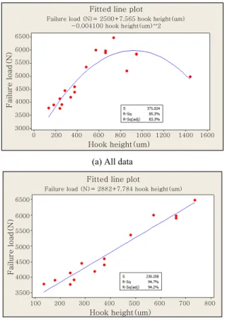
특히 CCW로 회전하는 경우 툴 이송 경로반경의 증 가에 따른 후크의 높이 증가가 크게 나타났다. CCW로 회전하는 실험번호들에 대해 측정된 후크의 높이와 파 단하중과의 관계는 Fig. 12와 같다. 800 μm이하의 후 크 높이에서는 파단하중과의 선형성이 강하게 나타나 며, 그 이상의 후크 높이에서는 오히려 파단하중이 더 낮다. 이는 교반력이 충분할 경우 후크가 발생하면서 접합력이 강하지만 일정 높이 이상의 후크가 생성되는
2000 3000 4000 5000 6000 7000 8000
Button Mixed
Failure load (N)
Failure mode Interface
Fig. 6 Relationship between failure mode and failure
load in the tensile shear testCW CCW
AS
PIN PIN
RS RS AS
Hook
Fig. 7 The comparison of hook location according to the
rotation directionHook
2mm
2mm Rotation direction: CW, Rotation speed: 300rpm, Rotation radius: 4mm, Travel speed: 60mm/min Rotation direction: CCW, Rotation speed: 300rpm, Rotation radius: 4mm, Travel speed: 60mm/min
Fig. 8 The hook formation according to the rotation di-
rectionRotation speed (rpm)
300 450 600
(a) Travel speed: 60 mm/min
(b) Travel speed: 120 mm/min
(c) Travel speed: 180 mm/min
Fig. 9 Cross-sections of cases with a rotation radius of
2mmRotation speed (rpm)
300 450 600
(a) Travel speed: 60 mm/min
(b) Travel speed: 120 mm/min
(c) Travel speed: 180 mm/min
Fig. 10 Cross-sections of cases with a rotation radius of
4mm경우에는 전단력의 전달에 불리하기 때문이다.
4. 결 론
본 연구에서는 툴 경로제어를 이용한 FSSW을 Al/
Fe 이종재료 겹침용접부에 적용하였다. 접합이 어려운 0.65 mm 강판을 하판으로 사용한 이종재료용접부에 해 당공정의 적용성을 검토하고자 실험분석을 적용하여 공 정변수와 전단인장 시험 시 파단하중와의 관계를 고찰
하였다.
1) 용접툴의 이송경로가 없는 일반적인 FSSW에서 접합이 어려운 0.65 mm 두께의 박판 철강 소재에 대 해서도 툴 경로제어를 이용할 경우 접합부에 홀이 발생 하지 않았으며 버튼 파단이 발생하는 용접강도 확보가 가능하였다.
2) 툴 회전방향, 툴 이송 경로반경, 툴 회전속도 및 이송속도를 주요인자로 실험계획을 적용한 결과 파단하 중에 영향을 미치는 주요 인자는 툴의 회전방향과 툴 이송 경로반경으로 분석되었다.
3) 툴이 원주 경로를 따라 이송하는 방향과 툴 자체 의 회전 방향이 일치하는 경우에는 후크가 이송 원주의 안쪽에 발생하고, 툴의 원주 이송방향과 툴 회전방향이 반대인 경우에는 후크가 이송 원주의 바깥쪽에 위치한 다. 후크가 이송 원주의 바깥쪽에 위치한 경우 더 높은 파단하중 확보가 가능하다.
4) 툴의 이송 경로반경이 증가하는 경우 접합계면의 면적의 증가와 후크의 높이 증가가 동시에 진행된다.
후크의 높이가 일정값(800 μm) 이하에서는 후크의 높 이와 파단하중은 선형적 관계를 가진다.
References
1. S. Imaizumi, Welding of aluminium to dissimilar metals,
Welding International, 10(8) (1996), 593-604
2. M. Kang, C. Kim, J. Kim, D. Kim and J. Kim, Corrosion Assessment of Al/Fe Dissimilar Metal Joint, J. of Welding
and Joining, 32(4) (2014), 393-400 (in Korean)
3. S. Katayama, Laser welding of aluminium alloys and dissimilar metals, Welding International, 18(8) (2004), 618-625
4. M. J. Kang and C. H. Kim, Cold-Metal-Transfer Arc Joining of Al 6K32 Alloy to Steel Sheets, Defect and
Diffusion Forum, 334 (2013), 247-251
5. M. Kang and C. Kim, Joining Al 5052 alloy to alumi- nized steel sheet using cold metal transfer process, Materials
& Design, 81 (2015), 95-103
6. A. Elrefaey, M. Gouda, M. Takahashi and K. Ikeuchi, Characterization of aluminum/steel lap joint by friction stir welding, Journal of materials engineering and per- formance, 14(1) (2005), 10-17
7. K. Kimapong and T. Watanabe, Lap joint of A5083 alu- minum alloy and SS400 steel by friction stir welding,
Materials transactions, 46(4) (2005), 835-841
8. K. Kimapong and T. Watanabe, Effect of welding proc- ess parameters on mechanical property of FSW lap joint between aluminum alloy and steel, Materials trans-
actions, 46(10) (2005), 2211-2217
9. Y. Chen, T. Komazaki, T. Tsumura and K. Nakata, Role of zinc coat in friction stir lap welding Al and zinc coat- ed steel, Materials Science and Technology, 24(1) (2008), 33-39
Interaction plot(data means)for hook height(um)
Fig. 11 Interaction effects of control parameters on height
of the hook0 200 400 600 800 1000 1200 1400 1600 Hook height(um)
6500 6000 5500 5000 4500 4000 3500 3000
Failure load(N)
Fitted line plot
Failure load (N)= 2500+7.565 hook height(um) -0.004100 hook height(um)**2
(a) All data
Fitted line plotFailure load (N)= 2882+7.784 hook height(um)
Hook height(um)
100 200 300 400 500 600 700 800
3500 4000 4500 5000 5500 6000 6500
Failure load(N)
(b) Data for hook height under 800 ㎛
Fig. 12 Relationship between height of the hook and fail-
ure load10. Y. Chen and K. Nakata, Effect of the surface state of steel on the microstructure and mechanical properties of dissimilar metal lap joints of aluminum and steel by friction stir welding, Metallurgical and Materials
Transactions A, 39(8) (2008), 1985-1992
11. C.-Y. Lee, D.-H. Choi, Y.-M. Yeon and S.-B. Jung, Dissimilar friction stir spot welding of low carbon steel and Al–Mg alloy by formation of IMCs, Science
and Technology of Welding & Joining, 14(3) (2009),
216-22012. T. Liyanage, J. Kilbourne, A. Gerlich and T. North, Joint formation in dissimilar Al alloy/steel and Mg alloy/
steel friction stir spot welds, Science and Technology
of Welding and Joining, 14(6) (2009), 500-508
13. A. Da Silva, E. Aldanondo, P. Alvarez, E. Arruti and A. Echeverria, Friction stir spot welding of AA 1050 Al alloy and hot stamped boron steel (22MnB5),
Science and Technology of Welding & Joining, 15(8)
(2010), 682-68714. E. Fereiduni, M. Movahedi and A. Kokabi, Aluminum/
steel joints made by an alternative friction stir spot welding process, Journal of Materials Processing
Technology, 224 (2015), 1-10
15. Y. S. Sato, H. Takauchi, S. H. C. Park and H. Kokawa, Characteristics of the kissing-bond in friction stir weld- ed Al alloy 1050, Materials Science and Engineering:
A, 405(1) (2005), 333-338
16. H. Badarinarayan, Q. Yang and S. Zhu, Effect of tool geometry on static strength of friction stir spot-welded aluminum alloy, International Journal of Machine
Tools and Manufacture, 49(2) (2009), 142-148
17. H. Badarinarayan, Y. Shi, X. Li and K. Okamoto, Effect of tool geometry on hook formation and static strength of friction stir spot welded aluminum 5754-O sheets,
International Journal of Machine Tools and Manufacture, 49(11) (2009), 814-823
18. S. Bozzi, A. Helbert-Etter, T. Baudin, B. Criqui and J.
Kerbiguet, Intermetallic compounds in Al 6016/IF-steel friction stir spot welds, Materials Science and Engineering:
A, 527(16) (2010), 4505-4509
19. G. Buffa, L. Fratini and M. Piacentini, On the influence of tool path in friction stir spot welding of aluminum alloys, Journal of Materials Processing Technology, 208(1) (2008), 309-317
20. Y. Chen, A. Gholinia and P. Prangnell, Interface struc- ture and bonding in abrasion circle friction stir spot welding: a novel approach for rapid welding aluminium alloy to steel automotive sheet, Materials Chemistry
and Physics, 134(1) (2012), 459-463
21. W. Yuan, R. S. Mishra, S. Webb, Y. Chen, B. Carlson, D. Herling and G. Grant, Effect of tool design and process parameters on properties of Al alloy 6016 fric- tion stir spot welds, Journal of Materials Processing
Technology, 211(6) (2011), 972-977
22. R. Justman, M. West, B. Jasthi, C. Widener and A. Boysen, Friction Stir Lap Welding Aluminum to Steel Using Scribe Technology (2013), http://met.sdsmt.edu/reu/ 2013/
2016/2012.Report/Final%2020Report.pdf
23. T. Curtis, C. Widener, M. West, B. Jasthi, Y. Hovanski, B. Carlson, R. Szymanski and W. Bane, Friction Stir Scribe Welding of Dissimilar Aluminum to Steel Lap Joints, Friction Stir Welding and Processing VIII, 10.1002/9781119093343.ch18 (2015), 163-169
24. E. E. Patterson, Y. Hovanski and D. P. Field, Microstructural Characterization of Friction Stir Welded Aluminum- Steel Joints, Metallurgical and Materials Transactions
A, 10.1007/s11661-016-3428-4 (2016), 1-15
25. K. Ohishi, M. Sakamura, K. Ota and H. Fujii, Novel dissimilar spot welding of aluminium alloy and steel sheets by friction stirring: -Friction anchor welding of aluminium alloy and steel-, Welding International, 30(2) (2016), 91-97