1. 서 론
원자력발전소에는 다양한 재료로 제작된 압력기기들 이 서로 용접을 통해 연결되어 있다. 용접 공정은 반복 적인 팽창 및 수축으로 인해 용접 잔류응력을 발생시키 고, 열영향부(HAZ)에 경(hard)하고 인성(toughness) 이 낮은 미세조직을 형성시켜 기기의 건전성을 저하시 킬 수 있다. 따라서 원자력발전소 안전등급 기기의 제 작 기술기준인 ASME Section III, NB/NC/ND에서 는 용접에 따른 열영향부의 인성 저하를 방지하기 위해 용접 후 Table 1과 같은 조건으로 용접후열처리(Post-
Weld Heat Treatment, PWHT)를 수행하도록 규정 하고 있다 1-6) . 또한 상기 기술기준에서는 페라이트계 모재에 대해서 용접후열처리에 따른 기계적 물성 변화 를 사전에 확인하기 위한 모의 열처리 시험을 수행하도 록 규정하고 있어, 탄소강 기기를 용접할 경우 모재로 시험 쿠폰을 제작하여 용접후열처리 조건으로 열처리를 수행하여 기계적 물성 변화를 사전에 확인하여야 한다 7-9) . 한편, 원자력발전소에는 서로 다른 재료로 제작된 두 개의 압력기기를 용접할 경우가 많은데, 상기 기술기준 에서는 서로 다른 두 재료를 용접할 경우 용접후열처리 는 더 높은 온도 범위를 갖는 모재를 기준으로 용접후 열처리를 수행하도록 규정하고 있다. 이러한 경우 용접
P-No. 1 탄소강의 기계적 특성과 미세조직에 미치는 용접후열처리의 영향
이승건
*, †
․강용준*
․김기동*
․강성식**
* 한국기계연구원 부설 재료연구소 접합기술연구실
** 한국원자력안전기술원 원자력안전연구실
Effect of Post-Weld Heat Treatment on the Mechanical Properties and Microstructure of P-No. 1 Carbon Steels
Seung-Gun Lee*
,
†, Yongjoon Kang*, Gi-Dong Kim* and Sung-Sik Kang***Joining Technology Department, Korea Institute of Materials Science, Changwon 51508, Korea
**Dept. of Nuclear Safety Research, Korea Institute of Nuclear Safety, Daejeon 34142, Korea
†Corresponding author : [email protected]
(Received February 1, 2017 ; Revised February 7, 2017 ; Accepted February 24, 2017)
Abstract
This study aims to investigate the suitability of requirement for post-weld heat treatment(PWHT) temperature when different P-No. materials are welded, which is defined by ASME Sec. III Code. For SA-516 Gr. 60 and SA-106 Gr. B carbon steels that are typical P-No. 1 material, simulated heat treatment were conducted for 8 h at 610℃, 650℃, 690℃, and 730℃, last two temperature falls in the temperature of PWHT for P-No. 5A low-alloy steels. Tensile and Charpy impact tests were performed for the heat-treated specimens, and then microstruc- ture was analyzed by optical microscopy and scanning electron microscopy with energy-dispersive spectrometry.
The Charpy impact properties deteriorated significantly mainly due to a large amount of cementite precipitation when the temperature of simulated heat treatment was 730℃. Therefore, when dissimilar metal welding is carried out for P-No. 1 carbon steel and different P-No. low alloy steel, the PWHT temperature should be carefully selected to avoid significant deterioration of impact properties for P-No. 1 carbon steel.
Key Words : P-No. 1 carbon steel, Post-weld heat treatment, Impact toughness
ISSN 2466-2232
Online ISSN 2466-2100
후열처리 온도가 낮은 재료의 기계적 성질이 저하될 가 능성이 크므로 사전 모의 열처리 시험을 통해 높은 온 도의 용접후열처리 조건에 대한 적절성을 반드시 확인 해야 한다. 예를 들어 배관 재료(P-No. 1)와 밸브몸체 재료(P-No. 5A)를 용접할 경우 용접후열처리 온도가 상대적으로 높은 밸브몸체 재료(P-No. 5A)의 용접후 열처리 조건을 적용해야 하는데, 이러한 경우 배관 재 료는 기계적 성질이 저하되는 문제가 발생할 수 있으므 로 용접후열처리 조건에 대한 적절성을 사전에 확인해 야 한다.
본 연구에서는 P-No. 1 탄소강과 P-No. 5A 저합금강 이 용접될 때를 가정하여 용접후열처리 온도를 P-No. 5A 에 맞춰 모의 열처리 시험을 수행하였다. 또한 용접후
열처리에 따른 기계적 물성 및 미세조직 변화를 관찰하 여 원자력 발전소에서 빈번히 사용되는 P-No. 1 탄소강에 대한 용접후열처리 온도의 적절성을 확인하고자 한다.
2 실험 방법 2.1 실험재료
용접후열처리에 따른 P-No. 1 탄소강의 기계적 성질의 변화를 확인하기 위하여 P-No. 1 재료 특성을 대표하며, 원전에서 빈번히 사용되는 SA-516 Gr. 60(50mm t) 및 SA-106 Gr. B(46mm t)를 대상으로 모의 열처리 및 기계적 시험을 수행하였다. 참고로 SA-516은 ‘중, 저온 압력용기용 탄소강 판’이고, SA-106은 ‘고온용 이
P-No. (Section IX, QW-420)
Holding Temperature Range, °F(℃)
[Note (1)]
Minimum Holding Time at Temperature for Weld Thickness (Nominal)
½ in. (13mm) or less
Over ½ in. to 2 in.(13 to 50 mm
Over 2 in. to 5 in.(50 to 125 mm)
Over 5 in.
(125 mm)
1, 3 1,100-1,250
(595-675) 30 min 1 hr/in
(2 min/mm)
2 hr plus 15 min each additional inch (25mm) over 2 in. (50 mm)
2 hr plus 15 min each additional inch (2 hr plus 0.5 min/mm over 50 mm)
4 1,100-1,250
(595-675) 30 min 1 hr/in
(2 min/mm) 1 hr/in (2 min/mm)
5 hr plus 15 min each additional inch (5 hr plus 0.5 min/mm over 125 mm) 5A, 5B, 5C, 6 except
P-No. 6 Gr. 4 1,250-1,400
(675-760)
30 min 1 hr/in
(2 min/mm) 1 hr/in (2 min/mm)
5 hr plus 15 min each additional inch (5 hr plus 0.5 min/mm over 125 mm)
6 Gr. 4 1,050-1,150
(565-620)
7 1,300-1,400
(705-760) 30 min 1 hr/in
(2 min/mm) 1 hr/in (2 min/mm)
5 hr plus 15 min each additional inch (5 hr plus 0.5 min/mm over 125 mm)
9A Gr. 1 1,100-1,250
(595-675)
30 min 1 hr/in
(2 min/mm) 1 hr/in (2 min/mm)
5 hr plus 15 min each additional inch (5 hr plus 0.5 min/mm over 125 mm)
9B Gr. 1 1,100-1,175
(595-635)
10F Gr. 1 1,100-1,250
(595-675)
30 min 1 hr/in
(2 min/mm) 1 hr/in (2 min/mm)
5 hr plus 15 min each additional inch (5 hr plus 0.5 min/mm over 125 mm)
10I Gr. 1 1,300-1,400
(705-760)
11A Gr. 4 1,000-1,050
(540-565) 30 min 1 hr/in
(2 min/mm) 1 hr/in
(2 min/mm) 1 hr/in.
(2 min/mm)
15E Gr. 1 1,350-1,425
(730-775) 30 min 1 hr/in
(2 min/mm) 1 hr/in (2 min/mm)
5 hr plus 15 min each additional inch (5 hr plus 0.5 min/mm over 125 mm) P-Nos. 8, 34, 42, 43, 45,
and hard surfacing on P-No. 1 base metal whose reported carbon content is not more than 0.30%
PWHT neither required nor prohibited
Table 1 Post-weld heat treatment conditions required by ASME Sec. III, NX
음매 없는 탄소강 관’이며, 해당 재료들은 용접절차인정 을 위해 모재를 화학조성에 따라 구분할 때 P-No. 1 모재로 구분된다. 판재인 SA-516 Gr. 60은 열간 압 연 후 890℃에서 소준(normalized)된 상태로 제작된 재료이며, 관재인 SA-106 Gr. B은 열간마무리(hot- finished) 상태로 제작된 재료이다.
화학조성을 확인하기 위하여 OES(Optical Emission Spectroscopy)를 이용하여 분석하였고, Table 2에 화 학조성 결과를 나타내었다.
2.2 모의 열처리 시험
용접후열처리에 따른 모재의 기계적 물성을 확인하기 위하여 모의 열처리 시험 온도는 Table 1에서 제시하 는 P-No. 1의 용접후열처리 온도 범위(595~675℃) 및 P-No. 5A의 용접후열처리 온도 범위(675~760℃) 에서 각각 2개의 온도를 선정하여 610℃, 650℃, 690℃, 730℃로 하였다. 또한 기기의 제작 기술기준인 ASME Section III에 제시된 요건에 따라 Fig. 1과 같이 가열 속도, 유지시간 및 냉각속도를 선정하였다.
한편 Fig. 2와 같이 본 시험의 가열 조건에서 DSC (Di- fferential Scanning Calorimetry) 분석을 실시한 결 과, 모의 열처리 온도는 SA-516 Gr. 60(A 1 : 733℃) 및 SA-106 Gr. B(A 1 : 734℃)의 A 1 온도를 초과하지 않는 것을 확인할 수 있었다.
2.3 기계적 특성 평가 및 미세조직 분석
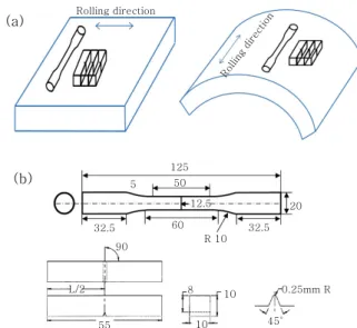
모의 열처리 전과 후 재료를 대상으로 Fig. 3과 같이 시편을 채취하여 ASME Section II, SA-370에 따라
Steel Fe C Si Mn P S Cr Ni Cu Mo Nb Al
SA-516 Gr. 60 Bal. 0.15 0.32 1.06 0.017 0.005 0.23 0.01 0.01 - 0.013 0.028
SA-106 Gr. B Bal. 0.17 0.36 0.64 0.013 0.004 0.11 0.09 0.15 0.06 - 0.033
Table 2 Chemical composition of the steels used (wt%)
Temperature[℃]
Target Temp.
8hr
3hr
Time[hr]
F.C
5hr 20min 3℃/m
in
427℃ 1.7℃/min (2〃
기준)
2hr 20min
1.7℃ /min (2〃
기준 )
3hr
13hr 20min 16hr 20min
Fig. 1 Schematic illustration of thermal history for si-
mulated post-weld heat treatmentHe a t fl o w (m W/ m g )
0.7
0.0 0.5 0.4 0.3 0.2 0.1
500 0.6
550 600 650 700 750
0.02 0.03 733 ℃ Derivative heat flow
Heat low
exo
0.00
-0.01 0.01
Der ivati ve h e at fl o w ( m W/ mg ℃ )
Temperature(℃)
(a)
he a t fl o w (m W /mg )
0.7
0.0 0.5 0.4 0.3 0.2 0.1
500 0.6
550 600 650 700 750
734 ℃
exo
Deri vativ e hea t flow (mW /mg ℃)
Temperature(℃)
Derivative heat flow Heat flow
0.02 0.03
0.00
-0.01 0.01
(b)
Fig. 2 DSC curves obtained during continuous heating
at heating rate of 1.7℃/min from 427 to 750℃:(a) SA-516 Gr. 60 and (b) SA-106 Gr. B
(a)
(b)
32.5
8 10 55
90
L/2 0.25mm R
10 45°
32.5 R 10 60
12.5 20 5 50
125 Rolling direction
Rolling direction
Fig. 3 (a) location of tensile and impact test specimens
and (b) their dimensions인장시험 및 Charpy 충격시험을 수행하였다. 이때, 인 장시험은 상온에서 수행하였으며, Charpy 충격시험은 3℃의 온도에서 실시하였다.
미세조직 분석을 위해 광학현미경(optical microscopy, OM), 주사전자현미경(scanning electron microscopy, SEM)을 사용하였으며, 시편은 표면 연마 후 3% Nital 용액으로 에칭(etching) 하였다. 또한 영상분석기(image analyzer)를 이용하여 페라이트 결정립 크기를 측정하 였다.
3. 결과 및 고찰
Fig. 4는 모의 열처리에 따른 재료의 인장 특성 변화 를 나타낸 것이다. 그림에서와 같이 모의 열처리 전 SA-516 Gr. 60의 항복강도 및 인장강도는 각각 327 MPa, 502 MPa 이며, SA-106 Gr. B의 항복강도 및 인장강도는 각각 304 MPa, 495 MPa이다. 모의 열처리를 수행한 결과 두 재료 모두 인장 강도가 감소 하였으며, 모의 열처리 온도가 높아질수록 감소 정도가 증가함을 확인할 수 있었다.
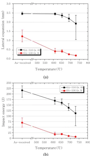
Fig. 5는 모의 열처리에 따른 재료의 충격 특성 변화 를 나타낸 것이다. 그림에서와 같이 두 재료 모두 충격 특성인 횡팽창량 및 흡수에너지가 모의 열처리 온도가 증가할 수록 감소하는 것을 확인할 수 있었다. 특히 P-No. 5A의 용접후열처리 온도 범위에 해당되는 73 0℃에서는 두 재료 모두 충격 특성이 급격하게 저하되 는 것이 확인되었다. 또한 SA-516 Gr. 60 및 SA- 106 Gr. B의 충격시험 파단면을 관찰한 결과 Fig. 6 과 같이 연성(ductile) 파괴와 취성(brittle) 파괴가 발생하는 것을 확인할 수 있었다.
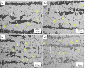
Fig. 7은 모의 열처리 전 두 재료의 미세조직 관찰 결과를 나타낸 것으로, 두 재료 모두 페라이트와 펄라
이트로 구성되어 있다. SA-516 Gr. 60의 경우 열간 압 연 후 소준 상태로 제작되었기 때문에, 미세한 결정립의
Temperature(℃)
SA-516 Gr. 60 SA-106 Gr. B
T e nsi le s tr eng th (MPa)
540
400 500 480 460 440 420
500 520
550 600 650 700 750 800 As-received
Fig. 4 Tensile strength of the steels as a function of post-
weld heat treatment temperatureTemperature(℃)
SA-516 Gr. 60 SA-106 Gr. B
Later a l exp a ns ion ( mm)
3.0
0.0 2.0
1.5
1.0
0.5
500 2.5
550 600 650 700 750 800 As-received
(a)
Temperature(℃)
Impact energ y (J)
225
0 100 125
50 25
500 250
550 600 650 700 750 800 As-received
175 150
75 200
SA-516 Gr. 60 SA-106 Gr. B
(b)
Fig. 5 Charpy impact properties of the steels as a func-
tion of post-weld heat treatment temperature: (a) lateral expansion and (b) impact energy(a) (b)
20㎛
20㎛ 20㎛20㎛
Fig. 6 SEM fractographs of the steels: (a) SA-516 Gr. 60
and (b) SA-106 Gr. B20㎛
20㎛
(a) (b)
Fig. 7 Optical micrographs of the steels: (a) SA-516 Gr.
60 and (b) SA-106 Gr. B
페라이트와 밴드(band) 형태로 배열된 펄라이트가 관 찰된 반면, 열간마무리(hot-finished) 상태로 제작된 SA- 106 Gr. B의 경우 상대적으로 조대한 결정립의 페라이트 와 펄라이트가 관찰되었다. 모의 열처리 전 각 재료의 펄라이트 영역에서의 경도를 측정해 본 결과 SA-516 Gr.
60의 평균값은 229.0 Hv이며, SA-106 Gr. B의 평 균값은 256.7 Hv로 확인되었다.
따라서, Fig. 5에서와 같이 모의 열처리 전 두 재료의 횡팽창량 및 흡수에너지가 차이를 보이는 것은 두 재료 간에 페라이트 상의 결정립 크기 및 펄라이트 상의 경 도 차이가 파괴 양상의 변화를 유발한 것으로 사료된다
10-13) .
Figs. 8-10과 14에 화살표로 표시한 바와 같이 모의 열처리 후에는 새롭게 생성된 상(phase)이 관찰되었고,
특히 P-No. 5A의 용접후열처리 온도 범위에 해당되는 730℃에서는 새롭게 생성된 상의 분율과 크기가 현저 하게 증가하는 것으로 보였으며, Fig. 10에 나타낸 바 와 같이 결정립계를 따라 film 혹은 massive 형태로 존재하였다.
새롭게 생성된 상에 대한 EDS 분석 결과를 Figs.
11과 12에 나타내었다. 해당 상의 크기가 작아서 정확 한 정량 분석은 어려웠으나, 기지(matrix) 조직에 비 해 탄소 함량이 상당히 높은 것을 확인할 수 있었으며, 따라서 새롭게 생성된 상은 고온에서 석출된 시멘타이 트(cementite)로 판단된다. 또한 Fig. 13의 파단면에 서 관찰되는 바와 같이 모의 열처리에 따라 석출된 시 멘타이트가 충격 특성 감소를 유발한 주된 원인으로 사 료된다.
(a) (b)
(c) (d)
20㎛
20㎛ 20㎛20㎛
20㎛
20㎛ 20㎛20㎛
Fig. 8 Optical micrographs of SA-516 Gr. 60 with a
post-weld heat treatment at (a) 610℃, (b) 650℃, (c) 690℃, and (d) 730℃(a) (b)
(c) (d)
20㎛
20㎛
20㎛
20㎛ 20㎛20㎛
20㎛
20㎛
Fig. 9 Optical micrographs of SA-106 Gr. B with a
post-weld heat treatment at (a) 610℃, (b) 650℃, (c) 690℃, and (d) 730℃(a) (b)
10㎛
10㎛ 10㎛10㎛
Fig. 10 Higher magnification optical micrographs of the
steels with a post-weld heat treatment at 730℃:(a) SA-516 Gr. 60 and (b) SA-106 Gr. B
(a) (b)
(c)
Fig. 11 Results of SEM-EDS analysis of newly formed
phase in SA-516 Gr. 60 after post-weld heat treatment at 730℃: (a) SEM image; EDS spectra from (b) point 1 and (c) point 2 shown in (a)(a) (b)
(c)
Fig. 12 Results of SEM-EDS analysis of newly formed
phase in SA-106 Gr. B after post-weld heat treatment at 730℃: (a) SEM image; EDS spec- tra from (b) point 1 and (c) point 2 shown in (a)한편, Fig. 14에 나타낸 바와 같이 모의 열처리 온 도가 730℃일 때 펄라이트의 구상화가 상당히 진행되 었음을 확인할 수 있었다. 모의 열처리 후 구상화 된 펄라이트에 대한 경도를 측정한 결과, SA-516 Gr.
60의 경우 평균값이 166.0 Hv이었고 SA-106 Gr. B 의 경우 207.7 Hv로, 모의 열처리 전과 비교해서 각 각 63.0 Hv와 49.0Hv 감소하는 것으로 확인되었다.
따라서 모의 열처리 온도가 730℃ 일 때 시멘타이트의 석출양이 현저하게 증가하는 것은 펄라이트 조직 내의 시멘타이트가 구상화되면서 일부 용해된 후 결정립계에 서 석출하였기 때문인 것으로 사료되며 14,15) , 이로 인해 충격 특성의 감소가 더 급격하게 나타나는 것으로 보인 다(Fig. 5).
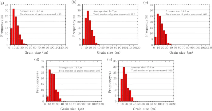
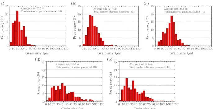
Figs. 15와 16에 모의 열처리에 따른 페라이트 결정 립 크기의 변화를 나타내었다. SA-516 Gr. 60의 페 라이트 결정립 크기는 큰 변화가 관찰되지 않은 반면 SA-106 Gr. B의 경우 페라이트 결정립 성장이 발생 한 것으로 확인되었다. SA-516 Gr. 60의 경우 판재 의 제조 공정 중 높은 변형량으로 인해 증가된 축적에 너지(stored energy)가 고온에서 회복(recovery)의 구동력(driving force)으로 작용하였기 때문에 페라이 트 결정립 성장이 지연된 것으로 생각된다 16,17) . 따라서 SA-106 Gr. B의 경우 모의 열처리로 인한 페라이트 결정립 성장 효과가 추가되어 SA-516 Gr. 60에 비해 충격 특성의 감소가 더 큰 것으로 보인다(Fig. 5).
(a) (b)
Fig. 13 (a) fracture surface of SA-106 Gr. B with a
post-weld heat treatment at 610℃ and (b) EDS analysis of the cementite taken from the rec- tangular area in (a)2㎛
2㎛ 2㎛2㎛
2㎛
2㎛ 2㎛2㎛
(a) (b)
(c) (d)
Fig. 14 SEM micrographs of the steels: (a, c) micro-
structure (as-received) of SA-516 Gr. 60 and SA-106 Gr. B; (b, d) microstructure (post-weld heat treatment at 730℃) of SA-516 Gr. 60 and SA-106 Gr. BF req ue ncy
(%)(a) 35
0 25 20 15 10 5
0 30
10
Grain size (㎛) 30 40 50 60
20 70 80 90 100 110 120 130
Average size: 12.3㎛Total number of grains measured: 450
(b)
Average size: 14.7㎛
Total number of grains measured: 312
(c)
Average size: 14.6㎛
Total number of grains measured: 402
F req ue ncy
(%)35
0 25 20 15 10 5
0 30
10
Grain size (㎛) 30 40 50 60
20 70 80 90 100 110 120 130
F req ue ncy
(%)35
0 25 20 15 10 5
0 30
10
Grain size (㎛) 30 40 50 60
20 70 80 90 100 110 120 130
F req uen cy
(%)35
0 25 20 15 10 5
0 30
10
Grain size (㎛) 30 40 50 60
20 70 80 90 100 110 120 130
F req uen cy
(%)35
0 25 20 15 10 5
0 30
10
Grain size (㎛) 30 40 50 60
20 70 80 90 100 110 120 130
Average size: 14.7㎛Total number of grains measured: 289
Average size: 15.8㎛
Total number of grains measured: 329
(d) (e)
Fig. 15 Ferrite grain size distribution of SA-516 Gr. 60 : (a) as-received; post-weld heat treated at (b) 610℃, (c) 650℃,
(d) 690℃, and (e) 730℃4. 결 론
P-No. 1 탄소강(SA-516 Gr. 60, SA-106 Gr.
B)를 대상으로 모의 열처리에 따른 기계적 특성 및 미 세조직의 변화를 관찰하였고, 다음의 결론을 도출하였다.
1) 인장시험을 통해 도출된 인장강도는 모의 열처리 온도가 증가함에 따라 감소하는 경향을 보였다.
2) 충격시험을 통해 도출된 횡팽창량 및 흡수에너지 는 모의 열처리 온도가 증가함에 따라 감소하였고, 730℃의 모의 열처리 온도에서 현저히 감소하였다.
3) 모의 열처리에 따라 석출된 시멘타이트가 충격 특 성 감소를 유발한 주된 원인으로 보이며, 특히 모의 열 처리 온도가 730℃일 때 시멘타이트의 석출양이 현저 하게 증가하기 때문에 충격 특성이 급격하게 감소하는 것으로 사료된다. 또한 SA-106 Gr. B는 모의 열처리 로 인한 페라이트 결정립 성장 효과가 추가되어 SA- 516 Gr. 60에 비해 충격 특성의 감소가 더 큰 것으로 보인다.
4) 따라서 P-No. 1 탄소강을 P-No. 5A 등의 저합 금강과 용접할 경우, 기술기준에 따른 용접후열처리 요 건을 적용하게 될 때 기계적 물성 저하가 발생될 수 있 으므로 용접후열처리 온도를 700℃ 미만으로 가급적 낮게 선택하거나, 용접설계 시 버터링을 고려하여 버터 링 및 본 용접 후 각각 용접후열처리를 수행하는 것이 인성 저하를 방지할 수 있을 것으로 판단된다.
후 기
본 연구는 원자력안전위원회와 원자력안전재단의 연 구비 지원으로 수행되었습니다.
References
1. G.M. Evans, The Effect of Stress Relieving on the Microstructure and Properties of C-Mn All-Weld Metal Deposits, Weld. J., 65-12 (1986), 326s-334s
2. A.G. Olabi and M.S.J. Hashmi, The Effect of Post-Weld Heat-Treatment on Mechanical-Properties and Residual- Stresses Mapping in Welded Structural Steel, J. Mater.
Process Tech., 55 (1995), 117-122
3. H.-T. Kim and S.-C. Kil, Trends of Welding Technologies (Heat Treatment), Journal of KWS, 21 (6) (2003), 3-11 (in Korean)
4. S.-S. Kang and Y.-J. Lee, Procedure of PWHT in Actual Welding Industry, Journal of KWS, 21 (6) (2003), 12-15 (in Korean)
5. S.-S. Kang and Y.-J. Lee, PWHT of Joint in Dissimilar Materials, Journal of KWS, 21 (6) (2003), 16-19(in Korean) 6. S. Paddea, J.A. Francis, A.M. Paradowska, P.J. Bouchard
and I.A. Shibli, Residual Stress Distributions in a P91 Steel-Pipe Girth Weld before and after Post Weld Heat Treatment, Mat. Sci. Eng. A, 534 (2012), 663-672 7. J.H. Kim and E.P. Yoon : Notch Position in the HAZ
Specimen of Reactor Pressure Vessel Steel, J. Nucl. Mater., 257 (1998), 303-308
8. Y.-S. Ahn, H.-D. Kim, T.-S. Byun, Y.-J. Oh, G.-M. Kim and J.-H. Hong, Application of Intercritical Heat Treatment
Fr equ enc y(% )
(a)
0 25 20 15 10 5
0 10
Grain size (㎛) 30 40 50 60
20 70 80 90 100 110 120 130
Average size: 24.7㎛
Total number of grains measured: 493
Average size: 34.8㎛
Total number of grains measured: 414
Average size: 40.8㎛
Total number of grains measured: 402
Average size: 33.5㎛
Total number of grains measured: 355 Average size: 20.5㎛
Total number of grains measured: 388
Fr equ enc y(% )
(b)
0 25 20 15 10 5
0 10
Grain size (㎛) 30 40 50 60
20 70 80 90 100 110 120 130
Fr equ enc y(% )
(c)
0 25 20 15 10 5
0 10
Grain size (㎛) 30 40 50 60
20 70 80 90 100 110 120 130
Fre que nc y(% )
(d)
0 25 20 15
10 5
0 10
Grain size (㎛) 30 40 50 60
20 70 80 90 100 110 120 130
Fre que nc y(% )
(e)
0 25 20 15
10 5
0 10
Grain size (㎛) 30 40 50 60
20 70 80 90 100 110 120 130
Fig. 16 Ferrite grain size distribution of SA-106 Gr. B : (a) as-received; post-weld heat treated at (b) 610℃, (c) 650℃, (d)
690℃, and (e) 730℃to Improve Toughness of SA508 Cl.3 Reactor Pressure Vessel Steel, Nuclear Engineering and Design, 194 (1999), 161-177
9. B.K. Choudhary, C. Phaniraj, K. Bhanu Sankara Rao and S.L. Mannan, Creep Deformation Behaviour and Kinetic Aspects of 9Cr-1Mo Ferritic Steel, ISIJ Int., 41 (2001), s73-s80
10. D. Lonsdale and P.E.J. Flewitt, The Role of Grain Size on the Ductile-Brittle Transition of a 2.25 Pct Cr-1 Pct Mo Steel, Metall. Trans. A, 9 (1978), 1619-1623 11. Y.M. Kim, S.K. Kim, Y.J. Lim and N.J. Kim, Effect of
Microstructure on the Yield Ratio and Low Temperature Toughness of Linepipe Steels, ISIJ Int., 42 (2002), 1571- 1577 12. B. Hwang, Y.G. Kim, S. Lee, Y.M. Kim, N.J. Kim and J.Y.
Yoo, Effective Grain Size and Charpy Impact Properties of High-Toughness X70 Pipeline Steels, Metall. Mater.
Trans. A, 36 (2005), 2107-2114
13. H. Qiu, T. Hanamura and S. Torizuka, Influence of Grain Size on the Ductile Fracture Toughness of Ferritic Steel,
ISIJ Int., 54 (2014), 1958-1964
14. A. Cabral, A.W. Thompson, I.M. Bernstein and D.H.
Stone, The Thermal Fatigue Behavior of Near-eutectoid Steel, Materials Science and Engineering, 93 (1987),
73-82
15. Y. Peng, H. Xu and M. Zhang, Effects of Simulated On- Fire Processing Conditions on the Microstructure and Mechanical Performance of Q345R Steel, Inter- na-
tional Journal of Minerals, Metallurgy and Materials, 23
(2016), 49-5616. R. Song, D. Ponge, D. Raabe and R. Kaspar, Microstructure and Crystallographic Texture of an Ultrafine Grained C-Mn Steel and their Evolution during Warm Deformation and Annealing, Acta Mater., 53 (2005), 845-858 17. A. Karmakar, M. Mandal, A. Mandal, M. B. Sk, S. Mukherjee
and D. Chakrabarti, Effect of Starting Microstructure on the Grain Refinement in Cold-Rolled Low-Carbon Steel During Annealing at Two Different Heating Rates,