KEPCO Journal on Electric Power and Energy, Vol. 2, No. 3, September 2016
Manuscript received May 9, 2016, revised August 10, 2016, accepted August 24, 2016 ISSN 2465-8111(Print), 2466-0124(Online), DOI http://dx.doi.org/10.18770/KEPCO.2016.02.03.421
This paper is licensed under a Creative Commons Attribution-NonCommercial 4.0 International License. This paper is available online at http://journal.kepco.co.kr 421
Analysis of Insulation Diagnosis and Failure in Stator Windings of Air-Cooled Gas Turbine Generator
Hee-Dong Kim†, Tae-Sik Kong, Kyeong-Yeol Kim
KEPCO Research Institute, Korea Electric Power Corporation, 105 Munji-Ro, Yusung-Gu, Daejeon, 34056, Korea
† [email protected]
Abstract
In order to evaluate the insulation deterioration in the stator windings of air-cooled gas turbine generators(119.2 MVA, 13.8 kV) which has been operating for more than 15 years, diagnostic test and AC dielectric breakdown test were performed on phases A, B and C. Diagnostic test included measurements of AC current, dissipation factor, partial discharge (PD) magnitude and capacitance. ΔI and Δtanδ in all three phases (A, B, and C) of generator stator windings showed that they were in good condition but PD magnitude indicated marginally serviceable condition. After the diagnostic test, an AC overvoltage test was performed by gradually increasing the voltage applied to the generator stator windings until electrical insulation failure occurred, in order to determine the breakdown voltage.
Although phase A of generator stator windings failed at breakdown voltage of 29.0 kV, phases B and C endured the 29.0 kV. The breakdown voltage in all three phases was higher than that expected for good-quality windings (28.6 kV) in a 13.8 kV class generator.
Keywords: Insulation deterioration, stator windings, Fault Detect and Diagnosis (FDD), air-cooled gas turbine generator, PD
I. INTRODUCTION
The stator winding of air-cooled gas turbine generators eventually breaks down after gradual insulation deterioration and partial discharge due to creation of internal voids, delamination, and contamination in the end-winding surface caused by thermal, electrical, mechanical, and environment stresses. In the case of the water-cooled generators, dielectric breakdown occurs due to vibration and corrosion of the stator winding, which are caused by leakage of cooling water and absorption of moisture. An unexpected dielectric breakdown in the stator winding insulation of large generators leads to degradation in reliability, and quick restoration is difficult; therefore, significant economic losses are incurred [1][2].
At present, a number of off-line insulation diagnostic tests are carried out to conduct insulation analysis of the gas turbine generator stator winding [3][4]. In Korea, insulation diagnostic tests are conducted regularly to evaluate the condition of the insulation aging of the generator stator winding, and research is being performed to determine the evaluation criteria for insulation deterioration. Furthermore, the insulation condition is evaluated by considering the overall insulation condition including the distribution pattern of partial discharge during operation. The extent of defects can be predicted by analyzing the trends and patterns obtained by examining the maximum partial discharge activity. These predictions can be used to understand the aging process of the insulation material.
In this paper, diagnostic and AC dielectric breakdown tests were carried out on stator windings of air-cooled gas turbine generator (119.2 MVA, 13.8 kV) that were built using the global vacuum pressure impregnation (VPI). The insulation condition of generator stator windings was assessed by analyzing the correlation between breakdown voltage and electrical characteristics of the diagnostic test.
II. EXPERIMENTAL PROCEDURE
Air-cooled gas turbine generators (119.2 MVA, 13.8 kV) had been in service for more than 15 years. The diagnostic test included measurements of polarization index (PI), AC current, dissipation factor (tanδ) and partial discharge (PD) magnitude. PI was measured using an automatic insulation tester (Megger, S1-5010) at DC 5 kV for each motor before applying AC voltage to the stator windings. Devices such as the mobile insulation diagnosis
& analyzing system (MIDAS, Tettex Instruments, 2880),
coupling capacitor (Tettex Instruments, 9,000 pF) and PD
detector (Robinson, DDX 9101) were used to measure the AC
current, dissipation factor and PD magnitude. AC voltage was
applied to the generator stator windings through a MIDAS
connected to the windings while the coupling capacitor amplified
the signals from the windings by sending it to the broadband
matching unit (Tettex Instruments, 9103) for the PD detector to
analyze the PD magnitude and pattern. The frequency band of the
PD detector ranged from 30 kHz to 400 kHz. Since the magnitude
of the PD in generator stator windings ranges between 12,400 pC
and 17,500 pC at 1.25 times of the line-to-ground voltage, it was
measured in a thermal power plant where background noise
ranged between 890 pC and 940 pC. The diagnostic and AC
dielectric breakdown tests were carried out on the stator windings
from generator at a voltage from 1.0 kV to 29.0 kV with increments
of 1.0 kV. After the diagnostic tests were completed, a variable
HV supply (AC 50 kV) was used to gradually increase the AC
voltage applied to each phase of generator in 1 kV intervals until
electrical breakdown occurred in the stator windings to measure
the AC current, dissipation factor and the breakdown voltage. The
diagnostic test method provides a good estimate of the breakdown
voltage for generator stator insulation.
Hee-Dong Kim, et al.: Analysis of Insulation Diagnosis and Failure in Stator Windings of Air-Cooled Gas Turbine Generator
422
III. CASE STUDY OF GROUND FAULT IN AIR-COOLED GAS TURBINE GENERATOR
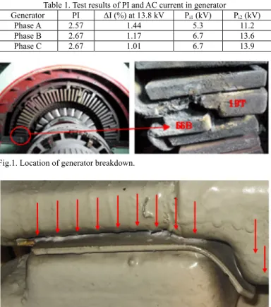
Three air-cooled gas turbine generators (119.2 MVA, 13.8 kV) shown in Fig. 1 were manufactured by the same company.
These generators were also produced using global VPI. Two generators had been in service for more than 14 years. The other one has been operating for more than 15 years. There were three generators in operation. A ground fault occurred in the phase-to- phase insulation of the end-winding in two air-cooled gas turbine generators when operating at rated output 82 MW. After the operation was stopped, the insulation resistance was found to be equal to 2 MΩ between phases A and B, whereas it was 3,000 MΩ at phase C. After disassembling the upper bracket of the generator, the location of the dielectric breakdown could be determined, as shown as in Fig. 1. The grounding occurred in the phase-to-phase winding at slot number 19T of the top coil of phase A and at slot number 66B of the bottom coil of the phase B. The first two generators were rewound. While proceeding diagnostic test, the last generator of the three also increased in PD magnitude from 8,300 pC to 17,500 pC at 10 kV. Therefore, the generator was also decided on rewinding.
The generator shown in Fig. 1 is of the global VPI insulation type where the connections of stator windings are installed close to each other. It can be seen in Fig. 2 that insulation separation is intended to function as a phase separator, and that a Nomex sheet is inserted between the two phases. However, this particular location has the highest potential difference; therefore, if the upper winding insulation of the figure contains an internal miniature void or gap that weakens its insulation, white powder is likely to occur due to the partial discharge (PD). If PD occurs continuously for a long period of time, the separator and the surface of the insulation material is eroded, which will lead to the
breakdown of the insulation.
IV. TEST RESULTS AND DISCUSSION
Before being rewound, the diagnostics tests were done. The insulation condition indicators measured from the diagnostics tests include the PI, the increase rate of charging current (ΔI), the increase of dissipation factor (Δtanδ), the maximum PD magnitude and the voltage at which charging current increases abruptly (P
i1, P
i2) : the first turning point voltage (P
i1) and the second turning point voltage (P
i2). The insulation condition can be assessed by comparing the diagnostic test results between the three phases of generator stator windings [5].
The PI will also tend to be high, in the range of 2.57 to 2.67 as shown in Table 1. The PI (above 2.0) of generator indicated that the stator windings are suitable for overvoltage testing [6].
Fig. 1 shows the change in current where the three phases encapsulated AC voltage was gradually increased in generator until insulation breakdown occurred. As can be seen from Fig. 1, there are two turning points (P
i1, P
i2) where AC current soared suddenly. As summarized in Table 1, ΔI at 13.8 kV ranged among 1.44%, 1.17%, and 1.01%, respectively. The ΔI of below 12% in a 13.8 kV generator is usually considered to indicate healthy insulation [7]; however, generator was determined to be in good condition because their ΔI was low with values between 1.01%
and 1.44% at 13.8 kV.
The P
i1voltage in phases A, B, and C of generator was 5.3 kV, 6.5 kV and 6.7 kV, respectively, and their P
i2voltage were 11.2 kV, 13.6 kV, and 13.9 kV, respectively. As the shown in Fig.
3, the AC current vs. voltage traces for generator was almost linear. These results indicate that the stator winding insulation of generator is in good condition.
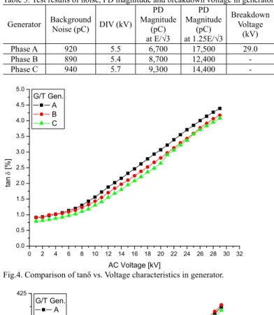
The change in the dissipation factor while AC voltage applied to the stator winding was gradually increased until it reached the breakdown voltage, as shown in Fig. 4. The Δtanδ had to be calculated based on the data from a 13.8 kV generator.
As it can be seen from Fig. 4, the dissipation factor increased abruptly about 3 kV. As summarized in Table 2, Δtanδ in phases A, B, and C of generator were 1.10%, 0.97% and 0.94%, respectively. According to [7], Δtanδ above 6.5% is considered to indicate bad insulation condition. Therefore, the insulation condition of the stator winding for all three phases of generator was assessed to be in good condition because their Δtanδ values were below 1.10% at 13.8 kV.
The capacitances measured as a function of applied voltage (up to 29.0 kV) in three phases of generator stator windings is shown in Fig. 5. The ΔC had to be calculated based on the data from a generator. As it can be seen from Fig. 5, the capacitances increased abruptly about 4 kV. As summarized in Table 2, ΔC measurements in phases A, B, and C of generator were among 1.58%, 1.31% and 1.21%, respectively. The values of the capacitance and dissipation factor in three phases A, B, and C of generator increased abruptly at 6 kV and 6 kV test voltages, as shown in Figs. 4 and 5.
The discharge inception voltage (DIV) and PD magnitude were measured while three phases encapsulated AC voltage was applied to the stator windings and the results are summarized in Table 3. The discharge inception voltage (DIV) refers to the voltage when the PD magnitude starts to exceed the background noise level of hundreds of pC, and goes above 1,000 pC. As can
Table 1. Test results of PI and AC current in generator Generator PI ΔI (%) at 13.8 kV Pi1 (kV) Pi2 (kV)
Phase A 2.57 1.44 5.3 11.2
Phase B 2.67 1.17 6.7 13.6
Phase C 2.67 1.01 6.7 13.9
Fig.1. Location of generator breakdown.
Fig.2. Distribution of white powder at the phase separator due to PD activity.
KEPCO Journal on Electric Power and Energy, Vol. 2, No. 3, September 2016
423
be seen from Figs. 4 and 5, the dissipation factor and capacitance increases the range of about 6 kV and 6 kV, respectively. DIV is also expected to occur within this range. The DIV measurements at the site were from 3.2 kV and 3.8 kV, as predicted. Therefore, when insulation deterioration occurs in the generator stator windings, increasing point of dissipation factor, P
i1of AC current and DIV both decrease, and dielectric breakdown voltage also decreases. The PD magnitude in phases A, B, and C of generator ranged among 17,500, 12,400, and 14,400 pC at 10 kV (1.25 times of the line-to-ground voltage). ΔI and Δtanδ in all three phases (A, B and C) of generator stator windings showed that they were in good condition but PD magnitude indicated marginally serviceable condition. The PD magnitude below 30,000 pC in phases A, B and C of generator was assessed to be in marginally acceptable condition. Periodic diagnostic test is strongly recommended for trending the insulation condition of these phases [7].
After the diagnostic test was completed, an AC overvoltage test was performed by gradually increasing the voltage applied to the stator windings until electrical insulation failure occurred, in order to determine the breakdown voltage. Phase A of generator stator windings failed at breakdown voltage of 29.0 kV. As shown in the case study above, it failed at the same spot. However, phases B and C endured the 29.0 kV. The breakdown voltage of three phases (A, B and C) of generator stator windings was higher than that expected for good-quality windings (28.6 kV) in a 13.8 kV class generator. The actual breakdown voltage of the generator stator winding was lower than the 2E+1 kV test voltage and the dielectric strength of each individual winding is still lower [8][9].
V. CONCLUSION
In this paper, a number of diagnostic and AC breakdown tests have been performed on the stator windings obtained from air-cooled gas turbine generators that were built using the global VPI. The conclusions drawn from the tests can be summarized as follows:
The measurements of ΔI and Δtanδ in all three phases showed the generator stator windings to be in good condition, although the PD magnitude measurement indicated that the insulation is marginally acceptable condition. The overall analysis of the results suggested that the generator stator windings were in marginally serviceable condition. Phase A of generator stator windings failed at breakdown voltage of 29.0 kV. As shown in the case study above, it failed at the same spot. However, phases B and C endured the 29.0 kV. The voltage at which dissipation factor and capacitance shows an abrupt increase is also similar as that of the DIV measurements. The point at which the dissipation factor in the tanδ-voltage curve increased was approximately 0.7 kV lower than the voltage at which Pi1 appeared in the AC current-voltage characteristics.
REFERENCES
[1] Hee-Dong Kim, “Analysis of Insulation Aging Mechanism in
Table 2. Test results of dissipation factor and capacitance in generatorGenerator Δtanδ (%) at 13.8 kV
tanδ increase voltage (kV)
ΔC (%) at 13.8 kV
ΔC increase Voltage (kV)
Phase A 1.10 6 1.58 6
Phase B 0.97 6 1.31 6
Phase C 0.94 6 1.21 6
Fig.3. Comparison of AC current vs. Voltage characteristics in generator.
0 2 4 6 8 10 12 14 16 18 20 22 24 26 28 30 32 0
500 1000 1500 2000 2500 3000 3500 4000 4500 5000
AC Current [mA]
AC Voltage [kV]
G/T Gen.
A B C
Table 3. Test results of noise, PD magnitude and breakdown voltage in generator Generator Background
Noise (pC) DIV (kV) PD Magnitude
(pC) at E/√3
PD Magnitude
(pC) at 1.25E/√3
Breakdown Voltage
(kV)
Phase A 920 5.5 6,700 17,500 29.0
Phase B 890 5.4 8,700 12,400 -
Phase C 940 5.7 9,300 14,400 -
Fig.4. Comparison of tanδ vs. Voltage characteristics in generator.
Fig.5. Comparison of capacitance vs. voltage characteristics in generator.
0 2 4 6 8 10 12 14 16 18 20 22 24 26 28 30 32 0.0
0.5 1.0 1.5 2.0 2.5 3.0 3.5 4.0 4.5 5.0
tan [%]
AC Voltage [kV]
G/T Gen.
A B C
0 2 4 6 8 10 12 14 16 18 20 22 24 26 28 30 32 395
400 405 410 415 420 425
Capacitance [nF]
AC Voltage [kV]
G/T Gen.
A B C
Hee-Dong Kim, et al.: Analysis of Insulation Diagnosis and Failure in Stator Windings of Air-Cooled Gas Turbine Generator
424