• 검색 결과가 없습니다.

Design of a Robust Controller for a Watertight Damper Driving System

N/A
N/A
Protected

Academic year: 2021

Share "Design of a Robust Controller for a Watertight Damper Driving System"

Copied!
7
0
0

로드 중.... (전체 텍스트 보기)

전체 글

(1)

http://dx.doi.org/10.7839/ksfc.2017.14.2.045

수밀댐퍼 구동장치의 강인제어에 관한 연구

Design of a Robust Controller for a Watertight Damper Driving System

한승훈

1

․장지성

2*

Seung Hun Han and Ji Seong Jang

Received: 11 Apr. 2017, Revised: 18 May. 2017, Accepted: 31 May. 2017

Key Words:Offshore Plants(해양플랜트), Watertight Damper Driving System(수밀댐퍼 구동장치), Pneumatic Driving System(공기압 구동장치), Sliding Mode Controller(슬라이딩 모드 제어기)

Abstract: Semi-submersible drilling rigs are offshore plants that perform functions such as ocean exploration for oil and gas acquisition, drilling and production, and storage and unloading of crude oil and gas. Semi-submersible drilling rigs use watertight dampers as emergency buoyancy holders. Since the watertight damper is an emergency shutoff device, it is mainly driven by a pneumatic driving system that can operate without a power supply. The pneumatic driving system has highly non-linear characteristics due to compressibility of air and external disturbance such as static and Coulomb friction. In this paper, a new control algorithm is proposed for a watertight damper driving system based on the sliding mode control with a disturbance observer. To evaluate control performance and robust stability of the designed controller, the control results were compared with the results obtained using the state feedback controller. As a result, it was confirmed that the pneumatic driving system for driving the watertight damper using the sliding mode controller with a disturbance observer can obtain excellent control performance against the parameter changes and the disturbance input.

* Corresponding author: [email protected]

1 Department of Control & Mechanical Engineering, Graduate School, Pukyong National University, Busan 48547, Korea 2 Department of Mechanical System Engineering, Pukyong National University, Busan 48547, Korea

Copyright Ⓒ 2017, KSFC

This is an Open-Access article distributed under the terms of the Creative Commons Attribution Non-Commercial License(http://

creativecommons.org/licenses/by-nc/3.0) which permits unrestricted non-commercial use, distribution, and reproduction in any medium, provided the original work is properly cited.

1. 서 론

Han et al.(2016) 등은 반잠수식 시추선의 해당하는 푼톤과 컬럼에 설치된 통풍용 공조덕트에 경량 수밀 댐퍼(Emergency Shut-off Damper, ESD)를 개발, 설치 하여 비상 사태시 컬럼에 부력을 확보하여 시추선의 침몰을 방지하고자 하였다.

1)

반잠수식 시추선은 원유 및 가스획득을 위한 해양 탐사, 원유 및 가스의 시추 및 생산, 저장, 하역 등의

기능을 수행하는 해양플랜트이다.

2-3)

반잠수식 시추 선은 비상용 부력 유지장치로서 수밀댐퍼를 사용한 다. 이때 수밀댐퍼는 비상용 차단장치이므로 수밀댐 퍼 구동에는 전원 공급 없이도 작동할 수 있는 공기 압 구동장치를 주로 사용한다.

4)

공기압 구동 장치는 압축성 유체를 사용하므로 강한 비선형성을 가지고 있고, 구동력에 비해 마찰력이 차지하는 비중이 크므 로 선형화 모델의 오차와 파라미터 불확실성에 매우 민감한 시스템이다.

5-6)

비선형 시스템을 대상으로 한 강인한 제어기 중에 서 가변구조시스템(variable structure system, VSS) 이 론

8-9)

에 근거한 슬라이딩 모드제어(sliding mode control, SMC) 기법은 이론의 간략성과 구성된 제어 시스템이 갖는 슬라이딩 모드라는 강인한 특성 때문 에 강인한 제어 성능이 요구되는 다양한 시스템에 적용되고 있다.

5-17)

본 논문에서는 수밀댐퍼 구동장치로서 랙 피니언

타입 공기압 구동장치를 대상으로 슬라이딩 모드제

(2)

어기와 외란관측기를 설계하여 구동시스템의 파라미 터 변화와 외란입력이 발생하여도 강인성과 우수한 제어성능을 얻을 수 있도록 하였다. 설계된 제어기의 성능은 상태 피드백 제어기를 이용한 시뮬레이션 결 과와의 비교를 통하여 검증하였다.

2. 수밀댐퍼 구동장치 모델링

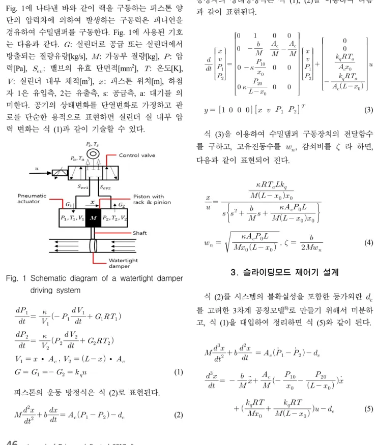
수밀댐퍼 구동장치의 개략도를 Fig. 1에 나타낸다.

Fig. 1에 나타낸 바와 같이 랙을 구동하는 피스톤 양 단의 압력차에 의하여 발생하는 구동력은 피니언을 경유하여 수밀댐퍼를 구동한다. Fig. 1에 사용된 기호 는 다음과 같다. : 실린더로 공급 또는 실린더에서 방출되는 질량유량[kg/s],  : 가동부 질량[kg],  : 압 력[Pa], 



: 밸브의 유효 단면적[mm

2

], : 온도[K],

 : 실린더 내부 체적[m

3

], : 피스톤 위치[m], 하첨 자 1은 유입측, 2는 유출측, s: 공급측, a: 대기를 의 미한다. 공기의 상태변화를 단열변화로 가정하고 관 로를 단순한 용적으로 표현하면 실린더 실 내부 압 력 변화는 식 (1)과 같이 기술할 수 있다.

Fig. 1 Schematic diagram of a watertight damper driving system

 



  

  

 



 



 



  

 

 



 



  ∙ 

 

    ∙ 

  

 

 

 (1) 피스톤의 운동 방정식은 식 (2)로 표현된다.

  

   

  



 

  

(2)

식 (1), (2)에서 사용된 기호는 다음과 같다.

: 비열비, : 피스톤의 전 행정[m], 

: 피스톤의 수압면적[m

2

], 

: 제어입력·유량[(kg/s)/V], : 제어입 력[V], : 동마찰계수[N/(m/s)], : 기체상수[J/(kgK)],

: 마찰력(⋅  

) [N], : 정마찰계수,

: 외부 부하력 실린더 평형위치에서   

,

  ,   

 



 

, 

 



 

로 가 정하고 출력을 피스톤의 위치라고 하면, 수밀댐퍼 구 동장치의 상태방정식은 식 (1), (2)을 이용하여 다음 과 같이 표현된다.



 

 

   



   



 

 



       

  

(3)

식 (3)을 이용하여 수밀댐퍼 구동장치의 전달함수 를 구하고, 고유진동수를

, 감쇠비를

라 하면, 다음과 같이 표현되어 진다.

 

  

        





    









  



    

 (4)

3. 슬라이딩모드 제어기 설계

식 (2)를 시스템의 불확실성을 포함한 등가외란

를 고려한 3차계 공칭모델

8)

로 만들기 위해서 미분하 고, 식 (1)을 대입하여 정리하면 식 (5)와 같이 된다.

  

   

 

 

  

  

 

       

  



    





  



     



  

(5)

(3)

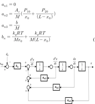
Fig. 2는 본 논문에서 설계한 등가외란을 고려한 수밀댐퍼 구동장치의 3차계 공칭 모델이다. 식 (5)에 서 실제 시스템 파라미터 공칭값인 



 



 



그 리고 

을 사용하여, 파라미터 불확실성 및 부하 외 란를 포함하는 등가외란 

를 적용한 제어 입력 



에 대해서 정리하면 식 (6)과 같이 나타낼 수 있다



 

 



 



 

 



 

  



  



식 (6)에 기술한 



 



 



그리고 

을 구하면 식 (7)과 같이 된다.

(7)

Fig. 2 Block diagram of the third order nominal model of watertight damper driving system

슬라이딩 모드 제어기는 식 (8)과 같이 3차의 슬라 이딩 평면이 영점(zero)으로 수렴하도록궤적 추종 제 어를 한다. 추종해야할 추종 오차는 위치 오차

, 속 도 오차



, 가속도 오차



이다. 슬라이딩 모드 제어 입력 는 Lyapunov 함수에 의해 결정되며 가 0에 수렴하기 위해서는 식 (9)의 조건을 만족해야 한다.

슬라이딩 모드 제어 입력 는 식 (10)과 같이, 연속 함수로 구성된 등가입력



와 슬라이딩 평면에서 등가외란을 보상하기 위한 스위칭 입력

로 구성하 였다.

  

  

, (8)

    

,    

,    

  

   ≤  (9)

  



 

(10)

식 (9)에서  일 때, 즉 시스템의 응답이 슬라 이딩 모드 상태에 있을 때, 식 (11)에 추종 오차를 대 입하여 



에 관해서 정리하면 식 (12)가 얻어진다.

이 때 

는 계측이 곤란하기 때문에 

대신에

  로 적용하였다.

11)

이 때 는 양의 상수이다.

 

 

  (11)



 

 



      



 

 



 



  

 



(12)

또한 스위칭 입력

는 식 (13)과 같이 나타낼 수 있다.

는 스위칭 평면상의 부호 상태에 따라 불연 속적인 제어입력으로 슬라이딩 모드가 설정된 궤적 을 추종하도록 제어 구조를 변화시켜준다.  는 부호함수이고,

는 스위칭 게인이다.

       

   

 

  

  

(13)

슬라이딩 모드 제어기만으로도 외란과 파라미터 불확실성에 대처가 가능하지만 등가 외란의 크기에 따라 스위칭 게인

가 지나치게 커지는 문제가 발 생할 수 있다. 이는 불필요한 채터링으로 인해 소음 및 진동을 유발할 수 있다.

15)

따라서

의 크기를 줄 이기 위해 슬라이딩 모드에 외란관측기(Disturbance Observer, DOB)를 설계하여 결합한 제어기 (SMC-DOB)를 설계하였다.

SMC-DOB 설계에서 외란 관측기는 외부 외란

에 대해

  

으로 두고 아래와 같이 확장된 시스템을 고려하여 설계하였다.

18)

식 (6)의 3차계 공칭모델에 외란을 추가하여 4차계로 확장된 시스템을 적용한 상태관측기는 식 (14)와 같이 나타낼 수 있다.

           (14)

   

여기서,







 



  

 



    





  

  



     



(4)

 

 

 

 

 

 

  

 

,

 

=

 × 

  × 

  × 

  × 

식 (14)에서 는 관측기 게인값이다. 는 극배치법 으로 결정되며, 시스템의 대표 극점은 응답특성이 양 호하도록 –100±87

(

≒ rad/s,  ≒0.75)로 설계 하였고, 나머지 극점은 경험적으로 5~10배 위치로 선 정하였다.

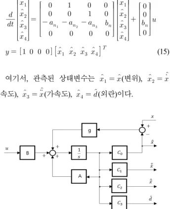
식 (15)는 관측기 상태방정식을 나타낸다. 외란관 측기 블록선도는 Fig. 3과 같이 나타낼 수 있다.

 

 

   

 

 

 

 

       

 

 

 

(15)

여기서, 관측된 상태변수는  

  (변위),  

  

(속도),  

  (가속도),  

  (외란)이다.

Fig. 3 Block diagram of disturbance observer

Fig. 4 Block diagram of a sliding mode controller with disturbance observer(SMC-DOB)

Fig. 4는 슬라이딩 모드 제어기에 외란 관측기를 부가한 구조를 나타낸다. 외란 관측기로부터 관측된 속도( )와 가속도( )가 제어기로 피드백 되며, 관측 된 외란  을 이용하여 시스템에 가해지는 제어 입력 의 보상이 이루어진다.

4. 결과 및 고찰

본 논문에서는 설계된 슬라이딩 모드 제어기의 타 당성을 검증하기 위하여 상태 피드백 제어기를 이용 한 결과와 비교하였다.

제어계 설계 사양은 단위스텝 입력에 따른 최대 오버슈트 

가 15%이내, 정착시간은 

(±1% 오차 기준)가 0.35초 이내 그리고 90% 상승시간 

이 0.2 초 이다. Table 1은 구동장치의 물리적 파라미터이고, Table 2는 설계된 슬라이딩 모드 제어기의 파라미터 를 나타낸다.

Table 1 Physical parameters of the driving apparatus

4.90265 · 10

-4

[m

2

]

340 [kPa]

50 [N/(m/s)]

287 [J/(kgk)]

5.06 · 10

-3

[(kg/s)/V]



max.18.46 [mm

2

]

0.5 [m]

293 [K]

1.5 [kg]

0.25 [m]

591.6 [kPa]

1.4

Table 2 Designed parameters of the sliding mode controller(SMC)

0.05  4.77×10

5

10000

200

본 연구에서 설계한 상태 피드백 제어기는 Fig. 5 와 같이 구성하였다. Fig. 5에서

[V/m],

[V/m

2

],

[V/m/s

2

]는 각각 비례게인, 속도게인 및 가속도게 인을 나타낸다. Fig. 5와 같은 제어기를 구성하는 경 우 식 (16)의

를 조절하면 목표하는 이득여유 및 위상여유를 임의로 설정할 수 있다.

19)

 ·



 



 ·



 

 

 (16)

(5)

Fig. 5의 제어 게인

,

는 식 (3)의 공 칭모델과 식 (16)를 이용하여 각각 4, -0.0355, -0.0034 로 설정하였다.

Fig. 5 Block diagram of the state feedback controller(PVA controller)

(a) PVA controller

(b) SMC controller

Fig. 6 Position control results when initial pressure changes

(

: 0.25 [m],  : 1.5 [kg])

Fig. 6은 평형 위치에서의 실린더 압력을 240[kPa], 340[kPa], 440[kPa]으로 설정한 경우의 제어결과를 나 타낸다. 압력 변화에 따라 압력 진동주기가 변화하므 로 PVA 제어기 (a)는 오버슈트가 크게 증가하여 제

어계 설계 사양을 만족할 수 없었고, SMC 제어기 (b)는 압력 변화를 잘 보상하여 우수한 제어 성능을 보임을 알 수 있다

Fig. 7은 피스톤의 초기위치가 변할 때 SMC 제어 기를 이용한 제어 결과를 나타낸다. 횡축은 시간을 나타내고, 종축은 피스톤의 위치를 무차원화한 결과 이다. 목표 스텝을 0.1[m]로 설정하고, 피스톤의 초기 위치를 0.1~0.25[m]까지 변화하였다. Fig. 7로부터 오 버슈트가 약간 증가되었으나 정착시간이 거의 동일 함을 알 수 있다.

Fig. 8은 피스톤의 초기 위치를 0.25[m]로 설정하 고, 가동부 질량을 각각 0.5[kg], 1.5[kg], 2.5[kg]으로 변화시킨 경우의 응답을 비교한 결과이다. 가동부 질 량이 변하면 정착시간이 다소 변하지만 제어계 설계 사양을 만족함을 알 수 있다.

Fig. 7 Position control results with SMC when initial position changes

( : 1.5 [kg], 

: 340 [kPa])

Fig. 8 Position control results with SMC when moving mass changes

(

: 0.25 [m], 

: 340 [kPa])

(6)

Fig. 9는 –0.2[m]의 스텝형 외란을 제어시작 후 1초 가 경과하였을 때 인가한 결과를 나타낸다. Fig. 9로 부터 SMC만을 이용한 경우에는 외란에 의하여 정상 상태 오차가 발생하였지만, 외란관측기를 부가한 SMC-DOB를 이용하면 외란이 인가되어도 정상상태 오차가 발생하지 않음을 알 수 있다.

Fig. 9 Position control results using SMC and SMC-DOB when disturbance is applied (disturbance : -0.2 [m], step input : 0.1 [m],

: 0.25 [m],  : 1.5 [kg], 

: 340 [kPa])

5. 결 론

본 논문에서는 수밀댐퍼용 공기압 구동장치의 비 선형성, 파라미터 변화 및 외란입력에 대하여 강인성 과 우수한 제어성능을 얻을 수 있는 강인제어기를 설계하였고, 다양한 조건하의 모의시험을 실시하여 그 결과를 분석하였다. 본 연구에서 얻어진 성과는 다음과 같다.

(1) 공기압 구동장치의 수학모델을 이용하여 외란 관측기가 부가된 슬라이딩모드 제어기를 설계하였다.

(2) 설계한 제어기를 적용한 결과 구동장치의 파라 미터가 변하여도 설계사양을 만족하는 우수한 제어 성능을 얻을 수 있음을 확인하였다.

(3) 슬라이딩모드 제어기에 외란관측기를 부가하여 외란이 입력되어도 정상상태 오차가 발생하지 않도 록 하였다.

후 기

이 연구는 지역주력산업육성(R&D) 기술개발사업 (과제번호 : R0004946)의 연구비지원에 의하여 수행 되었음을 밝힙니다.

References

1) S. H. Han, J. S. Jang and S. W. Ji, "Design of a Light Weight Damper for Offshore Rigs", The Korean Society Fisheries And Science Education, Vol. 28, No. 5, pp. 1470-1477, 2016.

2) B. K. An and H. J. Oh, "Semi-submersible Drilling Rig and Drilling Equipment", Journal of Ocean Engineering and Technology, Vol. 26, No. 6, pp.

86-87, 2012.

3) K. H. Kim, H. S. Choi and S. Hong, "Dynamic Position Control Method for Buffer Unit of a Deepsea Mining System", Journal of the Society of Naval Architects of Korea, Vol. 39, No. 3, pp.

57-63, 2012.

4) S. C. Jang, N. S Hui and I. W. Kim, "Performance Experiment of H-120 Class Fire Damper for offshore" J. of Korea Society of Manufacturing Process Engineers, Vol.13, No.2, pp.131-136, 2014.

5) J. S. Jang, S. W Ji and Y. B. Kim, "LMI-Based Controller Design of Pneumatic Cylinder" Journal of the Korean Society Fluid Power Systems and Construction Equipment, Vol.5, No.1, pp.1-5, 2008.

6) S. W Ji and J. S. Jang, "Design and Building of Flow-rate Measurement Apparatus for Compressible Fluid" Journal of the Korean Society Fluid Power Systems and Construction Equipment, Vol.10, No.4, pp.29-33, 2013.

7) S. Umerujan, N. Umeda, Hanamoto and T. Tsji,

"Model Reference Sliing Mode Control of Flexible Arm with Non-linear VSS Observer" Proc. of 3rd Asian Control Conference, pp.2893-2898, 2000.

8) I. C. Baik, K. H. Kim and M. J. Youn, "Robust Nonlinear Speed Control of PM Synchronous Motor using Boundary Layer Inergral Sliding Mode Control Technique," IEEE Transactions on Control

Systems Technology, vol.8, No.1, pp.47-54, 1993.

9) V. I Utkin, "Control System of Variable Structure", J Wiley and Sons Inc., New York, 1976.

10) R. A Decarlo S. H Zac and G. P. Mathews,

"Variable Structure Control of nonlinear

multivariable Systems:Atutorial.", IEEE Transactions

on Industrial Electronics, vol.111, pp.212-232,

1988.

(7)

11) I. H. Kim and Y. I. Son, "Design of a DC Motor Current Controller Using a Sliding Disturbance Observer and Controller" J. of Control, Robotics and Systems, Vol.22, No.2, pp.417-423, 2016.

12) T. H. Lee, J. H Park and S. S. Han, "A Study on the Sliding Mode Control of Nonlinear Systems" J.

of Electronics and Information Engineers, Vol.22, No.6, pp.590-596, 1994.

13) V. I Utkin, "Sliding Mode Control Design Principles and Application to Electric Drives", IEEE

Transactions on Industrial Electronics, vol.40, No.1,

pp.23-36, 1993.

14) V. I Utkin and J. Shi, "Integral Sliding Mode in Operating under Uncertainty Conditions", Pro. of the 34th IEEE conf. Decision and Control, pp.4591-4596, 1996.

15) J. J Slotin and S. S. Sastry, "Tracking Control of Non-linear Systems using Sliding Surface with Application to Robot Manipulator" J. of

International Control, Vol.38, No.2, pp.465-492, 1983.

16) R. G Morgan and U. ozguner, "Decentralized Variable Structure Control Algorithm for Robot Manipulator" IEEE Transactions on Control Systems

Technology, vol.8, No.-1, pp.57-65, 1985.

17) J. Y. Park, T. B. Lee and H. K. Choi, "Robot Manipulators Control using Variable Structure System Theory" J. of KITE Electronics Engineering, Vol.2, No.2, pp.2, 1991.

18) J. Birk and M. Zeitz, "Extended Luenberger Observer for nonlinear multivariable system", International Journal of Control, Vol.47, No.6, pp.1823-1836, 1987.

19) H. Hanafusa, "Design of Electro hydraulic Servo

Control System for Articulated Robot Arm

Control," The Japan Hydraulics & Pneumatic

Society, Vol.20, No.7, pp.429-436, 1982.

수치

Fig.  1  Schematic  diagram  of  a  watertight  damper  driving  system                                                               ∙          ∙             
Fig.  2  Block  diagram  of  the  third  order  nominal  model  of  watertight  damper  driving  system
Fig.  4  Block  diagram  of  a  sliding  mode  controller  with  disturbance  observer(SMC-DOB)
Fig. 7 Position  control  results  with  SMC  when  initial  position  changes
+2

참조

관련 문서

In this paper, a new discrete variable structure controller based on a new sliding surface and the discrete version of a disturbance observer is suggested for the control of

The numerical simulation demonstrates that the designed sliding mode controller proves its effectiveness for the jet engine by showing superior control

It can be concluded that, in sinusoidal case, adaptive sliding mode compensation controller based on LuGre friction model and force ripple can achieve much

For the compliance, the ISMC(Integral Sliding Mode Control) and HDOB(Human Disturbance Observer) The human force is identified by using the human band pass filter and its

In this study, the electronic wedge brake is modeled into dynamic equations, and a sliding mode controller is designed based on the model.. The performance of the

This paper deals with the disturbance observer (DOB) based sliding mode control (SMC) for a DC motor to control motor rotating speed precisely and to ensure strong robustness

A PD Controller and Sliding Mode Controller have been designed and their performance been tested through simulation to track a desired trajectory under the disturbance of

In this paper, therefore, a novel sufficient condition of discretized equivalent control based sliding mode controller (SMC) for a second-order system with external disturbance to