Analysis on Application of Flywheel Energy Storage System for offshore plants with Dynamic Positioning System
Hyun-Woo Jeong1․Yoon-Sik Kim†․Chul-Ho Kim2․Sung-Hwan Choi3․Kyoung-Kuk Yoon4 (Received:October 16, 2012; Revised October 25, 2012 ; Accepted:October 30, 2012)
Abstract:This paper describes a study of conventional electrical rig and simulated application of Flywheel Energy Storage system on the power system of the offshore plants with dynamic positioning system with the following aims: improve fuel consumption on engines, prevent blackout and mitigate voltage sags due to pulsed load and fault. Fuel consumption has been analyzed for the generators of the typical drilling rigs compared with the power plant with Flywheel Storage Unit which has an important aid in avoiding power interruption during DP (Dynamic Positioning) operation. The FES (Fly wheel Energy storage System) releases energy very quickly and efficiently to ensure continuity of the power supply to essential consumers such as auxiliary machinery and thrusters upon main power failure. It will run until the standby diesel generator can start and supply the electric power to the facilities to keep the vessel in correct position under DP operation. The proposed backup method to utilize the quick and large energy storage Flywheel system can be optimized in any power system design on offshore plant.
Key words:FES (Flywheel Energy Storage system), DP (Dynamic positioning system)
†Corresponding author (Division of Electrical and Electronic Engineering, Korea Maritime University, E-mail:
[email protected], Tel: 051-410-4411)
1 Korea Maritime University, E-mail: [email protected], Tel: 010-7152-1925 2 Korea Maritime University, E-mail: [email protected], Tel: 051-410-4892 3 Korea Maritime University, E-mail: [email protected], Tel: 051-410-4892 4 Korea Maritime University, E-mail: [email protected], Tel: 010-5541-0424
1. Introduction
On board drilling rigs or ships, electric power is provided by several synchronous AC generators operating in parallel. Power plants have commonly four, six or eight generators connected to two, three, or four switchboards. The disadvantages of the electrical DP rigs or ships are high initial cost, complexity; low fuel efficiency to meet the DP class notation. The efficiency of the power plant is very low in the traditional rigs where fault tolerance is dependent on maintaining a large spinning reserve to prevent the blackout due to a single point failure such as fire, flooding, or short
circuit on the switchboard bus, and etc. A major failure mode is one that has effects that are equal to the designed worst case failure which is the loss of one transverse pair of thrusters either forward or aft or significant reduction in DP redundancy. In case one or more of the generators are running in parallel the power plant load will be thrown on the remaining online generator/generators instantaneously.
In accordance with class rules, when generators are operating at no load, at nominal voltage, and the specified sudden load is switched on, the instantaneous voltage drop at the generator terminals shall not be more than 15% of the
generators nominal voltage.
The generator voltage should be restored within 3% of the rated voltage within 1.5 sec. when the specified load is switched off suddenly, the instantaneous voltage rise shall not be more than 20% of the rated voltage. Transient frequency variations in the electrical network shall not be in excess of ±10% of the rated frequency with a recovery time to steady state conditions not exceeding 5 seconds when the maximum electrical step load is switched on or off. Overload, caused by the stopping of one or more generators, shall not create a blackout.
There are several protection relays to be activated to protect the equipment and machines from damage. It is normally noted that two of protection relays contribute to tripping the circuit breaker of the remaining generators. They are triggered faster than others, which will drop out from the online. One is the under frequency protection set as typical 54HZ with time delay of 5 sec. The other is under voltage protection set as at normally 70% of rated voltage. It can be resulted in condition of partial blackout as a consequence if the remaining generators do not decrease its load before the under frequency and voltage limit. One of the features of frequency converters for propulsion thrusters and other process motor drives such as drilling equipment (Top drive, draw work winch, mud pump, and etc), is the possibility to change the load within less than 100 mili second.
That has been used in the fast load reduction system. Propulsion thrusters and drilling equipment are typically the largest consumers in ships and rigs with electric propulsion [1].
This introduces large cost spending on maintenance and emission control issues since it is observed that diesel engines will be running at around less than 30% load under moderate weather condition. This problem is not unique to diesel
electric plants. An effective load control with FES can improve the situation.
The aim in this paper is to design new power system applicable for drilling Rigs or vessels to control the fuel consumption as a minimum and prevent overload and blackout at fast increase of generator load in D.P mode. In the event of diesel generator failure, the FES will provide power for bus loads until a second diesel generator set can be brought online. Typical drilling rig equipped with DP system is used as a case study and the new power plant concept is proposed and simulated in coordination with FES.
2. Proposed Electrical Power system
2.1 Flywheel Energy Storage Systems
The FES consists of a high-inertia composite rotor spinning on a shaft supported by magnetic bearings in a vacuum enclosure. A PM (Permanent-magnet) motor is mounted on the shaft.
The motor is driven with a variable voltage, variable frequency DC-to-AC inverter.
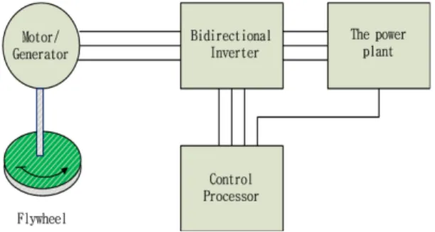
Figure 1: Flywheel Electrical Interface
Figure 1 shows the natural interface to the system, which is connected to a fixed frequency, bi-directional inverter for connection to an AC system. Unlike a battery, which stores energy chemically, the FES stores energy in rotational kinetic form. To charge the flywheel, current is delivered to the motor, which spins up the rotor.
When the rotor reaches full speed, the FES is fully charged. To discharge, the motor acts as a generator and is driven by the kinetic energy stored in the rotor[4]. Apart from the flywheel additional power electronics is required to control the power input and output, speed, frequency etc. The kinetic energy stored in a flywheel is proportional to the mass and to the square of its rotational speed according to Equation (1)
(1)
where E is kinetic energy stored in the flywheel, J is moment of inertia and ω is the angular velocity of the flywheel. The moment of inertia for any object is a function of its shape and mass. For steel rotors the dominant shape is a solid cylinder giving the following expression for a J.
(2) where is the distance of the differential mass from the axis of rotation. In the case of a flywheel where the mass is concentrated in the rim at radius , then the moment of inertia is given by: (3) Substituting Equation (3) in (1) gives:
(4)
[4], which shows that high angular velocity is more important than mass to achieve high stored energy.
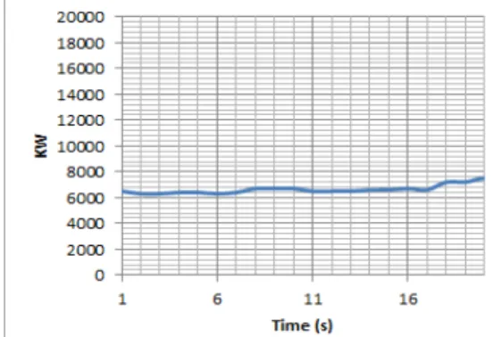
The FES storage capacity of proposed power plant needs a total of 150 MJ of delivered energy based on 2.5 MW of power for 1 minute discharging duration. It is enough stored energy for the standby generator to connect the online power after the running generator failure during normal DP condition as shown on the Figure 2.
It shows 4 of 8 generators are connected to the power plant grid, each capacity is 5MW and loaded at below 36% of each generator. The flywheel
Figure 2: Nominal power consumption at wind speed of 25knots and current of 2.5knots
designs included a preliminary composite body, steel stub shafts, magnetic radial and thrust bearings and coupling connection [5].
A conceptual flywheel design was developed incorporating the magnetic bearing sizing to provide overall scale for the energy storage system. The housing model includes radial and thrust magnetic bearing stators, a composite containment liner, and structural stainless steel vacuum enclosure. Overall dimensions and weights were compiled for the concept of FES configurations, and are listed in Table 1.
It should be noted that the dimensions include only the flywheel component and do not include the separately mounted motor generator.
Table 1: Flywheel design parameters
Parameter Value
Energy per FES (MJ) 150
Overall diameter(mm) 1054
Overall length(mm) 2286
Max shaft speed(rpm) 19146
Composite mas(Kg) 1150
Power per MG(Kw) 2500
2.2 Conventional Power System on the drilling rigs.
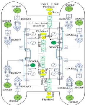
Figure 3 shows the popular arrangement for
semi-submersible rig. This design is based on a four-way split. Provided the power system is properly designed and protected, the worst case failure is now reduced to 25% of the power generating capacity and there should always be 6 thrusters available after any single failure. However, this arrangement is operated as two independent power systems in a two-way split with only three generators online on each split. In this configuration four thrusters can be lost if one split failure such as short circuit on the bus. This is a normal operating configuration for DP Class 3.
Figure 4: Four-way split for semi-submersible
2.3 Proposed Power System with FES
Figure 4 shows the FES systems are in standby mode and one generator is running on each split in two split configuration. During charge mode, the VFD (Variable Frequency Drive) interfacing the rig power system runs as a rectifier and the other as an inverter, with the transferred energy accelerating the flywheel to its rated speed. Energy is stored in the flywheel in the form of kinetic energy. The energy flow is from the rig power system to flywheel with induction machine as energy converter. Once the flywheel reaches its charge speed, the storage system is in standby mode and is ready to discharge when the load sees a voltage sag on the power network.
Figure 4: One generator operation with FES in D.P mode
Figure 5 shows The FES is in discharge mode.
The VFD interfacing the rig power system runs as an inverter injecting the required voltage in series with the line to mitigate the voltage dip. The flywheel VFD runs as a rectifier. The flywheel slows as it discharges. It will discharge until the stand-by generator is connected and completed load sharing.
Figure 5: FES in discharge mode
3. Experimental Results
DP class vessels usually operate with open bus-tie when in class 2 or 3 operations. By automatic splitting and segregation of the system, the faulty parts can be isolated and the intended redundancy obtained without loss of vessel’s station keeping ability. When the system is splited, the loss of any generator can influence only generators in that part of system, but not in the others. Even though the system becomes more robust to faults it also becomes less flexible to changing operational requirements, mainly due to segregation of consumers together with generators. The fuel consumption rate is increased in open bus-tie mode.
For diesel engines a continuous operation below 15% of rated power and above 100% rated power is not recommended [1].
A case study of drilling rig is used to explain the proposed method: The following assumptions is applied in the model:
1. Total installed load of all consumers is 36MW (Generators are 5MW at 0.8 P.F x 8 sets and thrusters are 3.8MW x 8sets)
2. For equally rated units the same BSFC (Brake Specific Fuel Consumption) curve and equal load sharing is used based on the maker data.
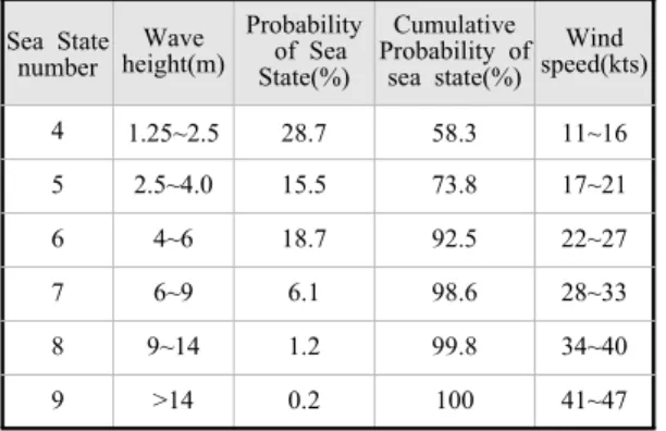
Table 2 shows typical probability of sea states for North Atlantic. A typical offshore drilling rig is most of the time in DP low operating mode.
Table 2: Probability of sea status for North Atlantic Sea State
number
height(m)Wave
Probability of Sea State(%)
Cumulative Probability of sea state(%)
speed(kts)Wind
4 1.25~2.5 28.7 58.3 11~16
5 2.5~4.0 15.5 73.8 17~21
6 4~6 18.7 92.5 22~27
7 6~9 6.1 98.6 28~33
8 9~14 1.2 99.8 34~40
9 >14 0.2 100 41~47
The DP low operating mode is from 4 to 6 in sea state number and high operating mode is from 7 to 9. The rig spends only 7.5% time per year in the high mode which is the operating mode with the highest loading. As shown in the Table 3 and Figure 2 the number of generators to be online shall be at least 6 for fulfilling the DP2~3 class under moderate weather condition. it will result in each generator operation with less than 24% of the generator capacity.
Figure 6, 7, and 8 show the real transient variation curves of the drill rig load when the two of three generators failure in parallel. Frequency dropped by 15.46 % of the rated frequency (which exceeds the limit (10%) the rule requires). The voltage dropped to 43.6% of the rated voltage more than 15% of the rated and recovered in 9sec.
Table 3: Total saved fuel compared with and without FES.
Without FSS With FSS
Load on each genset 24% 72%
The number of generators 6 2
Total consumed load 7.2MW 7.2MW
Fuel consumption 199g/kwh 188g/kwh
Ton per year 12551ton 11861ton
Saved fuel 0.00% 6%
Figure 6: Experimental result to voltage variation
the AVR and the governor of the generator is not capable of taking the instant load more than declared load (for example typical load at a step is 1/3 of the generator capacity). This generator is specified by the engine maker that the electrical system must be designed so that tripping of breakers can be safely handled.
Figure 7: Experimental result to frequency variation
This requires the engines to be protected from load steps exceeding their maximum load acceptance capability.
Figure 8: Experimental result to power variation
Application of FES was simulated and analyzed by giving the same parameters as shown on the Figure 12 and 13. it is indicated the FES helps the power system overcome voltage sag and frequency drop which has a risk of the tripping the remaining generator and creating blackout. The FES will respond within 30 cycles to keep the bus load
voltage within 3% tolerance.
Figure 9: Simulation result to voltage & frequency variation during FES in discharging mode.
4. Conclusion
This paper describes the advantage of the FES on the power plant of the drilling rigs or ships.
The dynamic D/G voltage and frequency variation tests for a Drilling Rig was carried out and examined. The application model of FES was simulated with transient voltage and frequency drop values compared with the actual values. The result obtained from the simulation shows the voltage is deviated by less than 1.5% and frequency less than 3% within 1/2 second in discharge mode upon main power failure. The proposed conceptual power plant can provide reduced number of power generators, improve the operability, prevent blackout in case of one or two generator failure. The power plant also makes the power stable even under large load fluctuation e.g.
abrupt motor starting or inrush current of the
transformer.
The FES can be used for many other functions on the oil plant, for example, the implementation of Flywheel storage system can result in the deletion of the Drilling VFD Braking Resistor. The Braking Resistor dissipates energy from the Draw works motors and Top Drive Motor thus preventing the system voltage from exceeding the rated DC bus voltage. Suitable switching arrangements would be required to implement the described voltage control.
Acknowledgement
This work is the outcome of a Manpower Development program for Maritime Energy by the Ministry of Land, Transport and Maritime Affairs (MLTM).
References
[1] Damir Radan, Asgeir J. Sorensen, Tor A.
Johansen and Alf Kare Ådnanes, “Probability based generator commitment optimization in ship power system”, Proceedings of the 10th World Scientific and Engineering Academy and Society, pp. 905-910, 2006.
[2] John McGroarty, Jesse Schmeller, and Richard Hockney, “Flywheel energy storage system for electric start and an all-electric ship”, Proceedings of the Electric Ship Technologies Symposium, pp. 400-406, 2005.
[3] Satish Samineni, “Modeling and analysis of a flywheel energy storage system for voltage sag correction”, International Electric Machines and Drives', vol. 3, pp. 1813-1818, 2003.
[4] Alan Ruddell, Investigation on Storage Technologies for Intermittent Renewable Energies, Report no.
WT-ST6 Flywheel, Institute of Electrical and Electronics Engineers, 2000.
[5] J. D. Herbst, A. L. Gattozzi and R.E. Hebner.
“Intelligent Micro-grid Demonstrator”, Proceedings of the Electric Machines Tech
Symposium, Philadelphia. PA, May 19-20, 2010.
[6] Jin-Seok Oh, Sung-Young Jung, Yeong-Kyung Kong, Jae-Goo Bin, and Han-Ho Kim, “Control algorithm development for design of cooling system in high-power propulsion motor”, Journal of the Korean Society of Marine Engineering, vol. 34, no. 1, pp. 195-201, 2010.