요지
본 논문은 골재부착력(aggregate retention) 평가를 통해서 칩실(chip seal)에서 사용되는 롤러 종류의 기초적인 연구 결과를 설 명하고 있다. 입도 78M의 화강암 골재와 CRS-2 이멀젼(emulsion)을 사용하여 single layer 칩실 테스트 구간을 시공하였으며, 3개 의 다른 롤러 종류를 사용하였다. 사용된 롤러 종류는 pneumatic tire roller, steel wheel roller, and combination roller를 사용하였 다. 세 종류의 롤러의 성능을 효과적으로 연구하기 위해서는 시공현장으로부터 직접 테스트용 시편을 얻는 것이 매우 중요하기 때문에, 노스캐롤라이나 주, Bailey에 있는 New Sandy Hill Church Road에서 테스트 구간 설정하고 일반적인 노스캐롤라이나 주의 칩실시공 절차에 준하여 시공을 실시하였다. 테스트 구간에서 제작된 시편들을 실험실로 옮겨서 골재부착력(aggregate retention) 성능평가를 실시하였다. 골재의 부착력을 평가하기 위해서 flip-over test(FOT), Vialit test, and the third-scale Model Mobile Loading Simulator (MMLS3) 시험방법들을 채택하였다. 세 가지의 시험결과들과 시험시공 현장에서 관측된 육안조사를 통해서 다음과 같은 롤러 종류와 순서를 추천하게 되었다. pneumatic tire roller 와 combination roller를 함께 사용하며 처음에 pneumatic tire roller가 다 짐을 한 뒤에 그 뒤를 combination roller가 다짐하는 순서로 다짐작업을 함으로써 칩실의 성능이 향상 되리라 사료된다.
핵심용어
칩실, 고무타이어 롤러, 스틸실 롤러, 소형포장가속시험기, 골재부착력
A Preliminary Study of Roller Types for Chip Seals Construction
Chip Seals 시공을 위한 롤러 종류에 따른 기초적인 연구이 재 준 Lee, Jaejun 정회원·한국건설기술연구원 수석연구원
김 영 수 Kim, R. Youngsoo 정회원·North Carolina State University 교수·교신저자 (E-mail : [email protected])
ABSTRACT
This paper presents a preliminary study of roller types for chip seals based on aggregate retention performance. Chip seal test sections composed of single seals of granite 78M aggregate and CRS-2 emulsion were constructed using three different roller types: the pneumatic tire roller, steel wheel roller, and combination roller. In order to investigate the performance of these rollers effectively, it is critical to test chip seal samples obtained directly from field construction. Therefore, test sections were constructed on New Sandy Hill Church Road near Bailey, North Carolina. Chip seal samples obtained from these sections were used for laboratory testing. The aggregate retention performance was evaluated using the flip-over test (FOT), Vialit test, and the third-scale Model Mobile Loading Simulator (MMLS3). Based on the test results and visual observation, both the pneumatic roller and the combination roller used together are recommended to improve chip seal performance with the sequence of the pneumatic roller rolling first followed by the combination roller.
KEYWORDS
chip seal, pneumatic tire roller, combination roller, steel wheel roller, MMLS3, aggregate retention.
한국도로학회 논문집 제12권 제3호 2010년 9월
pp. 79 ~ 85
1. INTRODUCTION
A chip seal is a typical pavement preservation treatment used by the most of State’s Department of Transportation (DOT) in
the United States. The chip seal is generally constructed in three steps: spraying emulsified asphalt, spreading a layer of aggregate, and finishing with rolling. The performance life of
Figure 1. Schematic diagram for determination of optimal roller type chip seals in North Carolina is typical 5 years, but about half of
that in Australia or New Zealand. One of the construction steps that need to be improved is the rolling process. Gransberg et al.
wrote an excellent report, Chip Seal Best Practices, which includes information from various countries, including New Zealand and Australia.(5)They report various types of rollers utilized for the chip seal compaction process; these types include the pneumatic tire roller, static steel roller, rubber-coated steel roller, a combination of the steel and the pneumatic tire rollers, and the vibratory steel roller. The purpose of rolling is to achieve the desired aggregate embedment depth (which is the principal criterion in the chip seal design) by redistributing the aggregate and seating it in the binder.(2)Another function of compaction is to achieve the bonding that results from proper embedment into the binder and from the most efficient orientation of the aggregates. Researchers have studied chip seal construction systems by roller type,(5)by rolling time,(4)by roller pass ,(6)and by roller weight(11)to improve the chip seal’s quality and performance.(5)
One of the critical failures of chip seals is aggregate loss. The greatest amount of aggregate loss occurs immediately after the pavement is open to vehicle traffic, especially if the chip seal has not had time to cure properly. The aggregate retention performance of the chip seal is improved when the rolling process creates the proper aggregate embedment into the thin emulsion film, which provides a firm mechanical interlock among the individual particles of aggregate. This paper presents the findings from a field and laboratory study aimed at ‘low hanging fruit’; that is, this study investigates relatively low-cost changes in the rolling procedure, in particular in terms of the type of roller used, that could significantly enhance the chip seal performance. The primary objective of this study is to determine the most effective roller type(s) for chip seal construction using
laboratory tests on chip seal samples obtained from actual field construction.
2. EXPERIMENTAL PROGRAM
Two types of rollers, the steel wheel roller and the pneumatic tire roller, are generally used in the United States to roll the aggregate during chip seal construction. A combination roller that combines the use of a rubber-coated steel wheel drum on one axle with a single row of rubber tire wheels on the rear axle is used in chip seal construction in New Zealand(12) and Canada .(3)
The primary objective of the experimental program is to preliminary study of an effective roller type for the chip seal construction. In order to investigate the performance as function of roller type, it is critical to test samples that have been obtained directly from field construction. To this end, test sections were constructed on New Sandy Hill Church Road (SR 1131) near Bailey in Wilson County, NC on June 12th 2007. The experimental program uses a single chip seal (straight seal) for the three test sections and three types of rollers: the steel wheel roller, the pneumatic tire roller, and the combination roller.
Figure 1 shows a schematic diagram for evaluating roller types for chip seal construction. It shows the layout of the three different rollers in a 300meter long section, which is divided into three 91.5meter long sections to allow one section per roller type, with a remaining 25.5meter section used for start-up. These 91.5meter long sections were used to fabricate the test samples, as follows. Once the templates are affixed onto the existing pavement for the entire 300meter length, the emulsion sprayer sprays emulsion. Next, the aggregate spreader spreads aggregate over the emulsion. Then, the three different rollers roll the aggregate immediately after the aggregate spreader has passed the start of each 91.5meter long section. Each section receives
three coverages. It is noted that the term number of coverages is used for the number of compactions experienced by a section of road. For example, Figure 2 shows one roller that passes three times to cover the entire lane with minimal overlap. In this case, the number of passes is three, but the number of coverages is only one. The aggregate and emulsion application rates (AARs and EARs) were determined from visual observations made by NCDOT Division Supervisors from a trial construction. The AAR and EAR for the single seals are 9.2kg/m2and 1.58 Liter/m2, respectively. Generally, the ranges of AAR and EAR for single seals vary as a function of aggregate type, size, and existing pavement condition. The detailed information was described at Gransberg et al.(5)Template for FOT and MMLS3 was designed with asphalt felt paper specified in ASTM D 266 as Type II(1). Vialit test template was made with steel plate.
3. FIELD SAMPLE FABRICATION PROCEDURE
One of the critical procedures in this research is establishing a proper field sampling procedure to obtain field samples that are representative of the actual construction sequence. The field sampling procedure was developed by NCSU research team.(7) Figure 3 describes the developed sampling procedure. Figure 3 (a) shows the placement of the templates on the existing pavement.
Templates for the FOT, Vialit test and MMLS3 test were affixed in the longitudinal direction to the ground paper that covers the existing pavement. It was observed in this project that segregation across the width of the aggregate spreader could lead to high sample-to-sample variability. This longitudinal layout helped reduce the sample-to-sample variation. The roller pattern in this
study is a parallel pattern that uses two rollers traveling in parallel within a section, as shown in Figure 3 (d). Figure 3 (e) shows the gathering of the samples for delivery. In order to reduce the disturbance of the aggregates during collection of the samples, the samples were cured for 30minutes at ambient temperature after completion of the rolling operation. This delay allowed time for an improved mechanical bond between the emulsion and the aggregate and, thus, the samples were more stable when they were handled and transported during the gathering process. Also shown in Figure 3 (e), samples were placed on a wooden plate to provide rigid support and further minimize disturbance during the delivery.
Collected samples on the wooden plates were stored on racks, as shown in Figure 3 (f).
4. TEST METHODS
4.1. Flip-Over Test(FOT)FOT(1)specimens were fabricated on a 25.4cm×25.4cm template(asphalt felt paper) in the field. The samples fabricated at the test sections were stored at room temperature (25℃) and
(a) affixed felt disks on the existing pavement (b) spraying emulsion
(c) spreading aggregate (d) compacting with rollers
(e) gathering samples (f) delivering samples to laboratory
Figure 3. Sample fabrication procedure Figure 2. Schematic diagram of three passes of one roller
were fully cured at 35℃ for 24hours prior to testing. Each specimen was turned vertically, and any loose aggregate was removed by lightly brushing the specimen. The specimens were weighed before and after the FOT to determine the amount of excess aggregate on the specimen.
4.2. Vialit Test
The Vialit test was generally used to evaluate aggregate retention. The Vialit test was developed by the French Public Works Research Group and standardized in British Standards (BS) 12272-3. The chip seal specimens obtained from the field were fabricated on 20cm×20cm steel plates and cured at 35℃
in the oven for 24hours prior to testing. For the Vialit test, a stainless steel ball is dropped three times from a height of 50cm onto a chip seal tray that has been inverted for 10 seconds. The sample weights are measured before and after the ball drop to calculate the percentage of aggregate loss using Equation (1).
(1)
where
= weight of aggregate on chip seal specimen before the test and
= weight of aggregate on chip seal specimen after the test.
4.3. MMLS3 Performance Test
The MMLS3 is a third-scale unidirectional vehicle load simulator that uses a continuous loop for trafficking. It is comprised of four bogies with only one wheel per bogie. These wheels are pneumatic tires that are 30cm in diameter, approximately one-third the diameter of a standard truck tire.
The wheels travel at a speed of about 5,500 wheel applications per hour, which corresponds to a dynamic loading of 3.3Hz on the pavement surface. This loading consists of a 0.3 second haversine loading time and a rest period of 0.3 second. The dynamic load on the pavement surface produced by the MMLS3 in motion is measured by a Flexiforce pressure sensor. The mean value of the maximum dynamic loads from the four wheels is approximately 3.57KN. The contact area is approximately 40cm2measured from the footprint of one MMLS3 wheel inflated to 101.5psi, thus resulting in a surface contact stress of approximately 1048.7KN/m2.(9)North Carolina
State University developed a test protocol for the performance evaluation of chip seals using the MMLS3 to measure aggregate retention performance. The detailed test procedure is described in Lee et al. (8)A brief outline of the test method is as follows:
First, a field specimen is cured for 24hours at 35℃ and 30±3%
relative humidity(RH) before testing, as specified in ASTM D 7000.(1) Then, the edges of the cured specimen are trimmed to produce a specimen that is 18cm wide and 36cm long. The 18cm width of the rectangular specimens is the same as the width of the wheel path under wandering MMLS3 loading. This design is necessary because it was found from former research that the aggregate that is lost under MMLS3 loading falls onto the untrafficked area, causing errors in the aggregate loss calculation.
(8)The trimmed specimen is mounted on a thin steel plate fastened to a steel base plate and then measured before and after the MMLS3 loading to determine the aggregate loss. MMLS3 loading is applied after a 3-hour temperature preconditioning period at 25℃. The aggregate loss during the initial traffic loading in the field (normally occurring within half a day) is measured after one wandering cycle of MMLS3 loading for 10 minutes (equivalent to 990 wheel loads). Then, MMLS3 loading is applied, and the weight of the specimen is measured at the end of a 2-hour loading period (equivalent to 11,950 wheel loads) to evaluate the aggregate retention performance of the chip seal under traffic.(8)
5. DISCUSSION OF RESULTS
5.1. Flip-Over TestThe FOT that is one of aggregate retention methods measures the amount of excess aggregate on the specimen. Figure 4 shows the percentage of aggregate loss of the single seal in terms of the three different roller types, as measured from the FOT. The percentage of aggregate loss represented in Figure 4 is determined from the weight of the aggregate using Equation.(1)The large empty circle symbol indicates the average of the data for each roller type. The percentages of aggregate loss of the combination roller and the pneumatic tire roller show a larger variation than that of the steel wheel roller, ranging from 4.4% to 8.7%, as shown in Figure 4. The range of the percentage of aggregate loss seen in Figure 4 is below the maximum allowable aggregate loss, 10%, as specified in the Alaska chip seal guide.(10)The pneumatic tire roller shows the lowest percentage of aggregate loss, 4.4%, among the three different rollers.
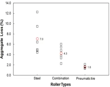
5.2. Vialit Test
The Vialit test measures the adhesion between the binder and aggregate. The adhesion is evaluated as the aggregate loss due to the shock of impact. The average aggregate loss percentages of the six replicates from the Vialit test were calculated and are plotted in Figure 5 against the roller types. It must be noted that the aggregate loss determined from the Vialit test using Equation (1) is based on the aggregate weight. The largest variance of aggregate loss occurred with the steel wheel roller, which is contrary to the FOT result. It is clearly seen in Figure 5 that the aggregate loss performance indicates a significant decrease in aggregate loss, although those values are below the maximum allowable aggregate loss, 10%, as specified in the Alaska chip seal guide.(12)The pneumatic tire roller shows the best aggregate retention performance, which is the same result as that obtained from the FOT.
5.3. MMLS3 Test
Figure 6 indicates a small variation in the single seal sample weights for the different roller types for the third-scale Model Mobile Loading Simulator (MMLS3) test, which is a similar result to that found in both the FOT and the Vialit test. Figure 6 shows the aggregate loss after a trafficking load for 2 hr. 10 min.
(12,940 wheel passes) using the MMLS3. Equation (1) was used to calculate the percentage of aggregate loss. A similar trend to that found from other aggregate retention tests (Figure 4 and Figure 5) is observed in Figure 6. The sample that was rolled by a pneumatic tire roller shows the lowest percentage of aggregate loss (3.7%). This percentage is nearly half of the others, 7.59%
and 6.16%. These results indicate that a pneumatic tire roller shows better aggregate retention performance than the other two rollers, as was found also in the FOT and the Vialit test.
5.4. Comprehensive Analysis
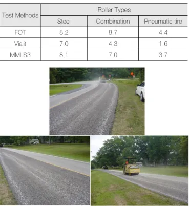
Table 1 summarizes the percentage of aggregate loss results obtained from the three aggregate retention tests. The steel wheel roller shows the poorest aggregate retention performance. It is known that the use of a steel wheel roller on chip seals can result in an unequal compaction force distribution across a lane because the surface of the steel roller drum is straight along the wheel axle direction, and an existing pavement surface can be uneven across a lane. Also, the steel wheel roller compaction force is concentrated on the hump (the highest area), thus causing the aggregate at those locations to break. Such breakage is usually found in the area next to the wheel path. The breakage is also related to aggregate quality, because poor quality aggregate has a greater potential to break. Figure 7 shows photographs taken at a secondary road in North Carolina of an Figure 4. Aggregate loss of a single seal obtained from FOT samples
Figure 5. Aggregate loss of a single seal from Vialit test samples
Figure 6. Aggregate loss of a single seal from MMLS3 samples
uneven rolling distribution.
The roller that offers the lowest aggregate loss percentage is the pneumatic tire roller, as indicated in Table 1. However, a visual observation of the chip seal surface rolled only by the pneumatic tire roller during the first experimental study reveals that the surface is much rougher than surfaces rolled either by a steel wheel roller or by a combination roller. These observations suggest the benefit of using both the pneumatic tire and combination rollers.
6. CONCLUSIONS
In order to preliminary study of effective roller type for chip seal pavements, the MMLS3, FOT, and Vialit tests were performed. Based on the test data obtained from this study, the following conclusions are drawn:
1. The field sampling procedure used in this study can be used to produce chip seal samples for laboratory testing without losing the properties of chip seal in the field.
2. All three aggregate retention tests clearly demonstrate that the rolling by the pneumatic roller produces chip seals with better aggregate retention performance than those rolled by the steel wheel and combination rollers. The difference in rolling performance between the combination and steel wheel rollers is much less clear.
3. Based on the results from aggregate retention performance tests and visual observation, both the pneumatic roller and the combination roller used together are recommended to improve chip seal performance. With regard to order, rolling should start with the pneumatic tire roller and finish with the combination roller to take full advantage of the pneumatic roller’s ability to produce chip seals with improved aggregate retention performance and the combination roller’s ability to provide a smoother, flatter finished texture than the pneumatic tire roller can provide.
ACKNOWLEDGMENTS
This work is supported by the North Carolina Department of Transportation (NCDOT) under Project No. HWY-2006-06. The authors wish to express gratitude to the NCDOT for supporting the project and providing the resources to construct the field sections.
REFERENCES
1) American Society for Testing and Materials. ASTM D 7000-04:
Standard Test Method for Sweep Test of Bituminous Emulsion Surface Treatment Specimen.
2) Benson, F. J. and B. M. Galoway. (1953). Retention of Cover Stone by Asphalt Surface Treatments. Bulletin 133, Texas Engineering Experiment Station, Texas A&M University System.
3) Croteau, J., P. Linton, J. K. Davidson, and G. Houston. (2005) Seal Coat Systems in Canada: Performances and Practice. 2005 Annual Conference of the Transportation Association of Canada, Calgary, Alberta. http://www.tac-atc.ca/english.pdf/conf2005/s15/croteau.pdf.
Accessed March 2008.
4) Gransberg, D. D., L. Karaca, and S. Senadheera. (2004). “Calculating Roller Requirements for Chip Seal Projects”. J. of Cons. Engin. and Man. ASCE., Vol.130, No. 3 pp. 378-384.
5) Gransberg, D. D. and David M. B. James. (2005). Chip Seal Best Practices. NCHRP Synthesis 342, Transportation Research Board, Washington, D.C.
6) Hudson, K. C., L. R. Saunders, K. F. Nicholls, and P. H. Hambleton.
(1986). Rolling of Chip Seals. 13th ARRB-5th REAAA Combined Conference 13: pp.173-186.
7) Lee, J., Y. R. Kim, and E. O. McGraw. (2006). “Performance Evaluation of Bituminous Surface Treatment Using the Third-Scale Model Mobile Loading Simulator”. J.Tra.Res. Board, TRB., No. 1958.
National Research Council, Washington D.C. pp. 59-70.
8) Lee, J. and Y.R.Kim. (2009) “Performance Evaluation of Chip Seals with Polymer-Modified Emulsions,”Journal of Association of Asphalt Paving Technologists, Vol. 78, 2009, pp. 103-136.
9) Lee, S. (2004). Long-Term Performance Assessment of Asphalt Concrete Pavement Using the Third Scale Model Mobile Loading Simulator and Fiber Reinforced Asphalt Concrete. Ph.D. Dissertation, Table 1. Summary of Average Percentage of Aggregate Loss
Figure 7. Uneven rolling under steel wheel roller
Test Methods Roller Types
Steel Combination Pneumatic tire
FOT 8.2 8.7 4.4
Vialit 7.0 4.3 1.6
MMLS3 8.1 7.0 3.7
North Carolina State University, Raleigh, NC.
10) McHattie, R. L. (2001). Asphalt Surface Treatment Guide. Alaska Department of Transportation.
11) Petrie, D. D., W. J. Sheppard, and L. R. Saunders. (1990). “Towards More Efficient Rolling of Chipseals”. Proceedings, IPENZ Annual Conference (February 12-17) pp. 291-300.
12) Transit New Zealand. 2005. Chipsealing in New Zealand. Transit New Zealand, Wellingington, Transit New Zealand.
접 수 일 : 2010. 5. 11 심 사 일 : 2010. 5. 17 심사완료일 : 2010. 8. 19