ISSN: 1738-7167
DOI: http://dx.doi.org/10.7731/KIFSE.2015.29.3.053
소방전원계통의 전원용량과 간선의 전압강하에 대한 문제점 분석
최승규 · 손봉세*
†
한국기술교육대학교, *가천대학교 소방방재공학과
Problem Analysis of Power Capacity and Main Line Voltage Drop of Electric Power System for Fire Protection
Seung-Kyou Choi · Bong-Sei Son*
†
Dept. of Electrical Engineering, Korea Technology Education Univ.
*Dept. of Fire & Disaster Protection Engineering, Gachon Univ.
(Received May 8, 2015; Revised June 8, 2015; Accepted June 22, 2015)
요 약
최근 소방대상물의 대형화는 소방전기계통의 용량과 간선길이를 급격하게 증가시키고 있어, 과거의 소규모 소방대상물 에서는 문제가 되지 않았던, 소방전원의 용량부족과 간선의 전압강하 증가로 규정전압을 벗어나는 문제점를 발생시키고 있다. 이러한 문제점은 소방용 전원전압이 규정전압에 미달되어 각종 전기설비가 동작하지 못하는 심각한 결과를 초례할 수 있다. 이에 본 논문에서는 실제 준공된 소방대상물을 대상으로 전원공급장치의 용량 및 소방전기간선의 전압강하를 이론적으로 계산하여 문제점을 도출하고 분석하여, 소방전원계통에서 소방용 전원의 안정적이고 합리적인 설계와 운용 에 대한 대책이 요구됨을 확인하였다.
ABSTRACT
The number of high-rise buildings and skyscrapers has increased drastically, and accordingly, the power capacities and main line lengths of electric power systems for fire protection are also rapidly increasing. This is generating new of prob- lems like shortages in power capacities and increases of main line voltage drops outside of the rated voltage range. This problem can have serious effects on fire protection systems and a variety of electric devices may not work properly in emergencies. As such, theoretical calculations were performed for these systems in an actual fire protection facility. The problems in the electric power system were extracted and analyzed, and the results show that it is necessary to search for new measures for the safe and rational design and operation of electric power systems for fire protection.
Keywords : Electric power System, Shortage of power capacity, Voltage drop
1. Introduction
Due to the recent drastic increase of high-rise buildings and skyscrapers, interlock systems for fire protection are getting more and more complex, and fire detection and alarm circuits are increasing greatly, which necessitates analogue addressable fire alarm systems with almost no limits in the number of circuits are designed and installed.
Unlike conventional fire alarm systems, analogue address- able fire alarm systems use devoted power supplies to sup- ply electric power to fire protection devices which are installed at electric power systems for fire protection at
buildings and plants.
Also, due to the recent drastic increase of sizes of fire protection facilities, the lengths and capacities of main lines which are required for monitoring and controlling a variety of fire protection systems are increasing rapidly.
As such, there is a new serious problem of shortage of capacities of power supplies and voltage drops of main lines for electric power system for fire protection, which was not a problem when fire protection facilities were small-sized. Presently, however, it is a fact that capacity of a power supply is designed, selected, distributed, and installed without exact theoretical grounds, depending on
†
Corresponding Author, E-Mail: [email protected]
†
TEL: +82-31-750-5713, FAX: +82-31-750-5713
designer’s experience only, due to the absence of the rele- vant regulations.
There is no problem of shortage of power supply and voltage drop of a main line at a normal time when a fire protection system performs monitoring only and, thus, needs a small amount of current. In case of a fire, however, a variety of fire loads activate intensively, increasing the load currents to their maximum, which in turn causes shortage of capacity of a power supply and voltage drops of main lines greatly.
Shortage of capacity of a power supply for fire protec- tion and voltage drop of a main line can cause a failure of a fire alarm system when the system is activated, which can cause serious injuries to people and damages to property in a fire emergency. This study calculates theoretically the capacity of a power supply and voltage drops of main lines of an electric power system for fire protection and extracts and analyzes the problems in the system, based on the schematic diagram of a fire alarm system of an actual fire protection facility.
2. Problem Analysis of Electric Power System for Fire Protection
In order to increase the practicality and reliability of this study, an actual fire protection facility has been chosen, and analysis has been made to the problems of the fire pro- tection facility, based on the schematic diagram of the elec- tric power system of the facility.
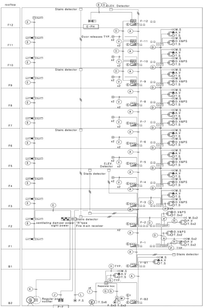
Figure 1 is a schematic diagram of a fire alarm system with which analysis can be made to the problems of the electric power system for fire protection. It can be seen from the figure that a variety of fire protection systems are installed at the facility, including fire alarm system, indoor hydrant system, sprinkler system, smoke control system, and other fire prevention systems.
There is only one power supply of which rated capacity is 360 W, while its supply voltage is 24 V DC and its rated current is 15 A. 1.5 SQ HIV (Heat-resistant indoor PVC insulated) cables are used for the main line of detectors while 2.5 SQ HIV (Heat-resistant indoor PVC insulated) cables are used for the main lines of other devices in accor- dance with the relevant regulations(3).
Capacity of a power supply and voltage drops of main lines of the electric power system for fire protection have been calculated and their problems have been analyzed below, based on the schematic diagram of a fire alarm sys- tem mentioned above.
2.1 Capacity of power supply for electric power system for fire protection
Capacity of a power supply for the electric power sys- tem for fire protection has been calculated, dividing its state into the supervisory state where supervision is made to the system and the emergency state where actual loads are activated in accordance with the relevant regulations, assuming fires in two places of the facility.
Figure 2 is a floor-by-floor distribution chart of fire pro- tection system load currents, assuming a case when a fire protection system is activated after detectors are activated on cross-zones of 1st floor and 10th floor, where fire loads are expected to be the largest.
As shown in the figure above, fire protection system load currents are 2.15 A of supervisory current and 12.69 A of operating current, totaling 14.84 A. Based on it, capacity of a power supply has been calculated, taking into account 1.2 safety factor due to yearly changes in accordance with the following formula (1)(1).
P = VI × 1.2 = 24 × 14.84 × 1.2 = 427.39 [W] (1) where :
V [V]: Load voltage I [V]: Load current
The rated capacity of a power supply for the electric power system for fire protection for this specific fire pro- tection facility is designed to be 360 W, while the neces- sary capacity of a power supply in case of fire emergencies in two places is 427.39 W, as shown in the formula above.
Thus, it is confirmed that the electric power system for fire protection for this building will not work properly, due to the shortage of capacity of the power supply in fire emer- gencies.
2.2 Voltage drop at Main Line of electric power system for fire protection
Just like calculations of load capacities of the electric power system for fire protection, voltage drops of main lines have been calculated, assuming fires in two places, based on two states, i.e. supervisory state where the sys- tem is supervised and emergency state where actual loads operate, taking into account the special nature of fire pro- tection facilities.
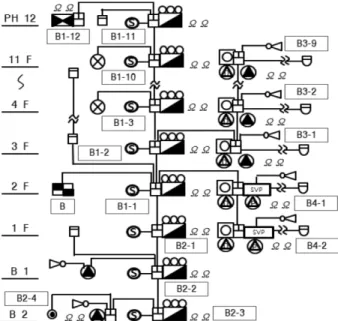
Since a fire alarm system is structured vertically, the electric power system has been estimated and analyzed, dividing it largely into smoke control damper section (Sec- tion A) and hydrant and sprinkler section (Section B),
Figure 1. Schematic diagram of fire alarm system.
while Section B in turn has been divided into upper floor hydrant section (Section B1), lower floor hydrant section (Section B2), upper floor sprinkler section (Section B3), and lower floor sprinkler section (Section B4), as shown in Figure 3 below.
In addition, section-by-section voltage drops of the main lines have been estimated and their problems have been identified, applying Formula 2, a theoretical formula for voltage drops.
e [V] = (35.6LI)/(1000A) (2)
where :
A: Section-by-section are a of cable L: Length of cable
I : Rated current
2.2.1 Voltage drop at Main Line “A” section of electric power system for fire protection
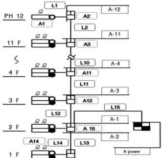
Voltage drops at smoke control motor damper section of Main Line “A” have been calculated, dividing the main line as shown in Figure 4 and using Formula (2) for each
section and Formula (3) for all the sections(2).
eA section =Σ(e12 eA-power supply) (3) Figure 5 shows a graph of section-by-section terminal voltages in a normal state and in an emergency state, which are converted, based on 24 V DC, the supply voltage of a power supply, and applying the voltage drops at Main Line
“A” section which are calculated, using the formula above.
Since a fire alarm system is specified to operate within 20% of the rated voltage, i.e. 24 V DC +/−20%(3), without any trouble in accordance with the relevant regulations, the operating voltage can range from 19.2 V DC to 28.8 V DC when it is converted into the terminal voltage. As a result of calculating section-by-section terminal voltages of Main Line “A”, it is confirmed that the voltages meet the rated Figure 2. Distribution chart of fire protection system load
current.
Figure 3. Settings diagram of electric power system for fire protection.
Figure 4. Configuration diagram of Main Line “A” of elec- tric power system for fire protection.
Figure 5. Terminal voltage of Main Line “A” section.
voltage in a normal state while the voltages in an emer- gency are lower than the rated voltage at Main Line “A-5”, as shown in the graph above.
2.2.2 Voltage drop at Main Line “B” section of electric power system for fire protection
Voltage drops and terminal voltages at Main Line “B”
section have been calculated in the same way as Main Line
“A” section, i.e. after dividing the line into Main Lines B1 to B4, as shown in Figure 6, and also dividing voltage drops into section-by-section voltage drops which exclude the fire detection system and terminal voltage drops which include the fire detection system.
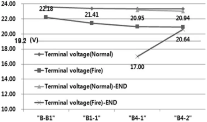
Figure 7 is a graph which shows the terminal voltages of the sections and the end of Main Line “B1”, which are con- verted from its voltage drops, based on 24 V DC, i.e. the supply voltage of the power supply.
Figure 6. Configuration diagram of Main Line “A” of elec-
tric power system for fire protection. Figure 8. Terminal voltage of Main Line “B2” section.
Figure 7. Terminal voltage of Main Line “B1” section. Figure 9. Terminal voltage of Main Line “B3” section.
It can be seen that the terminal voltages of the end of Main Line “B1” are 12.73 V DC in Section “B1-9” and 18.63 V DC in Section “B1-10”, respectively, both of which are less than the rated voltage, and, especially, that the terminal voltages of 10th floor (Section B1-9) go out of the rated voltage greatly, due to the activation of two door releases (operating current 600 mA) which are used for actuation of automatic fire doors.
Voltage drops and terminal voltages at the sections and ends of Main Lines “B2”, “B3”, and “B4” have been esti- mated in the same way as above. Figure 8 is a graph which shows the section-by-section terminal voltages of Main Line “B2”, from which it can be seen that the terminal voltages are 20.68 V DC or above even in an emergency, maintaining the allowable rated voltage well, because the system is short and the load current is not big.
Figure 9 is a graph which shows the section-by-section terminal voltages of Main Line “B3”, from which it can be seen that the terminal voltages are out of the rated voltage, starting from Section “B3-6”, and, especially, that the ter- minal voltages at 10th floor (Section B3-9) go far beyond the rated voltage, due to the generation of big voltage drops
caused by activation of a solenoid which is for actuation of a fire protection valve (operating current 850 mA).
Figure 10 is a graph which shows the section-by-section terminal voltages of Main Line “B4”. from which it can be seen that the terminal voltages of Section “B4-1” are less than the rated voltage, due to the generation of big voltage drops caused by activation of a solenoid which is used for actuation of a fire protection valve (operating current 850 mA), as Main Line “B3”.
Upon analysis of the problems of the electric power sys- tem for fire protection at the actual fire protection facility, it has been found that there is a problem that the fire alarm system does not operate properly, due to the shortage of capacity of power supply and the generation of voltage drops at all main lines, except Main Line B2, which exceed the allowable rated voltage.
3. Conclusion
This study calculates theoretically the capacity of a power supply and the voltage drops of main lines at an actual fire protection facility and extracts and analyzes the problems in the system in order to improve the irrational- ity in capacity calculations of electric power systems and distribution of power supplies which are designed arbi- trarily by designers, based on their experience only, and installed without the correct theoretical grounds, due to the absence of the relevant regulations.
Summarized below are the key points of this study.
(1) As a result of analyzing the problems in power capac-
ity and voltage drops of an actual electric power system for fire protection, based on theoretical calculations, it is found that the electric power system for fire protection does not operate properly, due to the shortage of its capacity and the generation of voltage drops at the main lines going out of the rated values.
(2) This study identifies the irrationality in capacity esti- mation of electric power systems for fire protection and distribution of power supplies, which designers are designed arbitrarily without correct theoretical grounds, based on their experience only, and proposes ways of improvement for rational operation and design of electric power systems.
(3) This study also suggests the problem of absence of the relevant regulations like no obligation to submit a cal- culation report of capacities and voltage drops of electric power systems for fire protection to the authorities having jurisdiction when applying for construction permits, as well as the grounds for the necessity of improving the relevant regulations.
References
1. KOFElS 0304, “Korea Fire Institute”, 3.15 (2013).
2. NFSC 203, “National Fire Safety Code for Automatic Fire Detection Equipment”, 8.1.2 (2013).
3. NFSC 203, “National Fire Safety Code for Automatic Fire Detection Equipment”, 8.1.4 (2013).
4. IEEE 1547.1, “IEEE Standard conformance Test Proce- dures for Equipment Interconnecting Distributed Resources with Electric Power System”, June (2009).
5. IEEE 1547.1, “IEEE Standard Conformance Test Proce- dures for Equipment Interconnecting Distributed Resources with Electric Power System”, June (2005).
6. D.-s. Rho, et al., “Optimal Algorithms for Voltage Man- agement in Distribution Systems Interconnected with New Dispersed Sources”, Korea Institute of Electrical Engineers, pp. 192-201, June (2011).
7. Adler, IEEE Standard Conformance Test Procedures for Equipment Interconnecting Distributed Resources with Electric Power System, IEEE 1547.6. (2009).
8. Brown, IEEE Standard Conformance Test Procedures for Equipment Interconnecting Distributed Resources with Electric Power System, IEEE 1547.1. (2005).
Figure 10. Terminal voltage of Main Line “B4” section.