논문번호 07-04-30 203
OTP: An Overlay Transport Protocol for End-to-end Congestion and Flow Control in Overlay Networks
Kyung-Hoe Kim
1, Pyoung-Yun Kim
2, Sung-Kwan Youm
2, Seung-Joon Seok *, and Chul-Hee
3Kang
1*
1
Dept. of Electronics and Computer Engineering, Korea University,
2Samsung Electronics Co. Ltd.,
3
Dept. of Computer Engineering, Kyungnam University
Abstract
The problem of architecting a reliable transport system across an overlay network using split TCP connections as the transport primitive is mainly considered. The considered overlay network uses the application-level switch in each intermediate host. We first argue that natural designs based on store-and-forward principles that are maintained by split TCP connections of hop-by-hop approaches.
These approaches in overlay networks do not concern end-to-end TCP semantics. Then, a new transport protocol – Overlay Transport Protocol (OTP) – that manages the end-to-end connection and is responsible for the congestion/flow control between source host and destination host is proposed. The proposed network model for the congestion and flow control mechanisms uses a new window size – Ownd – and a new timer in the source host and destination host. We validate our analytical findings and evaluate the performance of our OTP using a prototype implementation via simulation.
However, the usage of overlay networks may come with a price, usually in added latency that is incurred due to longer paths created by overlay routing, and by the need to process the messages in the application level by every overlay node on the path.
1. Introduction
With the increasing needs for multimedia applications, a number of services are deployed in the Internet. Over the last few decades TCP has served as the dominant protocol none the less because various network services are deployed in the current Internet. But TCP which generally used in the Internet cannot effectively cover all these services to provide various multimedia applications.
In overlay networks, the end-to-end connection must be split by hop-by-hop TCP connection because packets sent from a source node to a destination node experience application level layer in all intermediate nodes along the overlay path. Because of this split connection TCP end-to-end semantics are broken.
That is, congestion and flow control are performed not between the two end nodes but between the two adjacent nodes. We discuss these aspects and define the considered network in this paper in section 4.
Overlay networks are opening new ways to Internet usability, mainly by adding new services that are not available or cannot be implemented in the current Internet, and also by providing improved services. These networks deploy services with a virtual network over a physical network. That is, overlay networks have a topology which consists of nodes connected at the application level layer.
In section 2, previous works to provide reliable data transfer in overlay networks are introduced, evaluated by a qualitative analysis, and compared each other. The scenarios which are concerned in this paper are analyzed in section 3. The main
*Chul-Hee Kang and Seung-Joon Seok are co-corresponding authors.
204 전기전자학회 논문지(Journal of IKEEE) Vol. 11. No.4
contribution of this paper is guaranteeing the end-to-end congestion and flow control. To guarantee end-to-end reliable data transfer the method applying OTP on the edges of a connection and the congestion and flow control mechanisms are proposed in section 4. We demonstrate through simulation that our proposed approach provides performance improvements for the considered overlay network model in section 5 and conclude in section 6.
2. Related Works
As mentioned in previous section, an overlay network is a virtual network created on top of an existing network. All nodes which participate in the specific service organize a virtual topology by an application level connection between any two nodes. The nodes in the overlay network use each other as routers to send data. These overlay routers are responsible to route packets to a corresponding node and forward packets to a next hop. The connections between the overlay nodes are carried over the underlying network; in this case, the Internet.
Because all nodes which organize a virtual network topology have no concern whether through which path packets are delivered in a physical network, the increase of RTT might occurs in overlay networks. And the fact that packets sent from a source node to destination node experience an application level layer in all intermediate nodes along an overlay end-to-end path increase an end-to-end delay. But, overlay networks have the potential to improve the reliability perceived by applications because they permit aggressive path exploration and maintenance. Representative overlay network examples are as follows.
Transport layer approach in overlay networks has been performed over the last few years. Most papers about transport layer approach in overlay networks use a hop-by-hop connection approach which splits an end-to-end connection. H.
Pucha et al. [1] proposed overlay TCP (oTCP) that splits the direct TCP connection between any two hosts into a multiple-overlay-hop path. By splitting the direct TCP connection into multiple connections, RTT of each overlay hop is lower than the direct RTT between two end hosts of the direct TCP connection. Then, each overlay hop’s throughput will be higher than the direct throughput between two end hosts. But
oTCP doesn’t consider end-to-end reliability, per-hop congestion control, and TCP fairness. Only an improvement of each overlay hop’s throughput is handled. Y. Amir et al. [2]
proposed the method that can obtain end-to-end reliability by using TCP between two end hosts. But, because overlay path is mostly longer than the direct TCP path, it takes long to recover the packet loss. Y. Amir proposed the hop-by-hop reliability approach that enables a fast recovery by localizing the congestion. But, this approach will force us to break end-to-end semantics. And because packets which are transferred from a source node to a destination node pass through a transport layer, i.e. TCP, in all intermediate nodes along the overlay path, only using TCP between two end hosts cannot obtain end-to-end reliability. Different from the above two papers P. Karbhari et al.
[3] proposed the method that can determine the number of TCP connections on each overlay hop so as to maximize the throughput of the data carried end-to-end on a single overlay path. The basic idea that makes multiple connections between two adjacent nodes to maximize the throughput is very simple.
But because other transport protocol (e.g. parallel TCP) has to be used in each nodes in overlay networks, this approach cannot be deployable simply.
In this paper, OTP is proposed to guarantee an end-to-end reliability in overlay networks. In the next section, topology and nodes which are used in the considered overlay network and the protocol stack are introduced.
3. Case Study
3.1. Single End-to-end Overlay Path
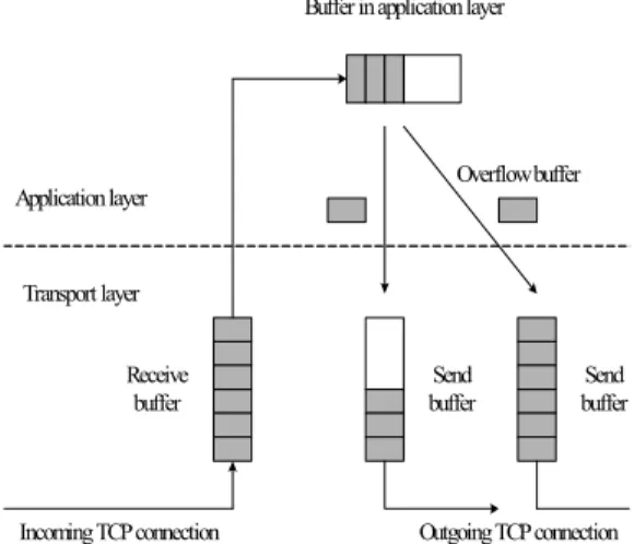
At the intermediate overlay node, the socket buffer for the incoming TCP connection forwards the data packets to an application layer buffer. This buffer then forwards the packets to the socket buffer for the outgoing TCP connection. See Fig. 1 for more details.
All segments from a previous hop are stored in a TCP receive buffer of an incoming TCP connection. A buffer in an application layer fetches these segments, stores in its buffer and then, hands down to a TCP send buffer of an outgoing TCP connection.
Our ultimate goal is to maximize the throughput of data
OTP: An Overlay Transport Protocol for End-to-end Congestion and Flow Control in Overlay Networks 205
carried on overlay TCP networks (see. section 2). We assume the existence of a separate routing infrastructure that determines the overlay path from a source to a destination. The main design parameter in this work is the sending window of a source node reflecting a receive buffer condition of a destination node. To understand the need for such a design, we define the separated rate of an overlay hop as the throughput
that a single long-lived continuously backlogged TCP connection would achieve on that hop. Now consider an overlay TCP path in which a single TCP connection is used on each hop. Clearly, the separated rates on the overlay hops are usually not equal, and vary over time. The end-to-end throughput on this path is limited by the minimum of the separated rates on the individual overlay hops.
If we set as the separated rate of the incoming hop and as that of the outgoing hop at any overlay node will generally be unequal.
R1
R2
R1<R2
1. If , the outgoing connection does not have enough data to operate at its separated rate ( ) and is limited by the data rate of the incoming connection ( ). This situation derives an end-to-end throughput degradation and also, since it is not continuously backlogged any more, it might repeatedly go into slow start and get an even lower throughput.
2. If , although the outgoing connection can now operate at the maximum rate ( ), the intermediate node has
R2
R1 Buffer in application layer
Send buffer Application layer
Transport layer
Receive buffer
Incoming TCP connection Outgoing TCP connection Send
buffer
Overflow buffer R1>R2
R2
O1
(Source) O2 Om
(Destination) Om-1
…
K1 K2 Km-2 Km-1
TCP connection Ki ith Overlay hop Oi ith Overlay node
Fig. 2. Model for single end-to-end overlay path
to buffer the excess data. Once the buffers at the intermediate node are full, the incoming connection has to throttle back. It can send more data only after the buffers have space to hold it.
The incoming connection is now bounded by the data rate of the outgoing connection. Also, now the incoming connection might go into repeated slow-starts, thus lowering the throughput even more. In compared with the first situation, this situation is even more serious degradation of an end-to-end throughput.
3. If Fig. 1. Overlay intermediate node implementation
R1=R2, the average connection rates over some time period T are equal. However, at any instant, each TCP connection will be in the slow start or congestion avoidance phase. These phases need to be synchronized in order to get the maximum effective throughput.
Our model for a single end-to-end overlay path is shown in Fig.
2. Consider a path of m nodes, each node denoted by Oi in the virtual network topology. These nodes are connected by m − 1 overlay hops, each denoted by Ki. As presented in Fig. 2, our model for a single end-to-end overlay path assumes that the number of TCP connection on each hop is only one TCP connection. The overlay path comprises one or more links and nodes in the underlying network. But our network model doesn’t consider the operation of this underlying network. We consider one-way data transfer on this path.
3.2. Multiple End-to-end Overlay Path
We consider the situation that multiple TCP connections might exist along the end-to-end overlay path in this section. As we discussed in the previous section, we focus on the situation that data comes in at the intermediate node at a rate slower than what can be forwarded on the outgoing hop.
Above all things, the basic multiple overlay path model that contains several source and destination nodes is defined.
206 전기전자학회 논문지(Journal of IKEEE) Vol. 11. No.4
Table 1. Congestion alarm according to buffer space Several sources send data to several destinations passing
through an intermediate node one after another. The model that contains one ingress node and one egress node between several sources and destinations can be characterized by two criteria.
They are whether they are many-to-one connection or one-to-many connection.
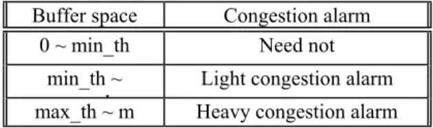
Buffer space Congestion alarm 0 ~ min_th Need not
min_th ~ Light congestion alarm max_th ~ m th Heavy congestion alarm
1. In a case that many-to-one connections in an ingress overlay node exist, because the number of incoming TCP connections is much larger than the number of outgoing TCP connection, a buffer overflow of outgoing TCP connection occurs in a short time unless the separate rate of the outgoing TCP connection is enough high. Although the link pass through the outgoing TCP connection is not a bottleneck link, these buffer overflows in the ingress overlay node can be a serious problem. If the link pass through the outgoing TCP connection is a bottleneck link, an overflow occurs in all buffers in the ingress overlay node as soon as several sources start data transmission.
Table 2. OTP operation according to CAbit
CAbit OTP operation
00 Do nothing
01 Send OCN message (light) 11 Send OCN message (heavy)
2. In a case that one-to-many connections in an egress overlay node exist, it doesn’t result in such serious buffer overflow problems like the many-to-one connection model, but a little bit of a possibility of a buffer overflow occurrence exists.
Because the number of outgoing TCP connections is much larger than the number of incoming TCP connection, the possibility of a buffer overflow occurrence of an outgoing TCP connection is not so high unless the separate rate of the incoming TCP connection is very high. That is to say, if burst data come into a buffer of the incoming TCP connection, a buffer overflow can occurs. If one of links pass through the outgoing TCP connection is a bottleneck link, an overflow occurs in all buffers in the ingress overlay node in a little time.
4. Proposed Mechanism
4.1. Considered Overlay Network Model
In defining the overlay network model considered in this paper, two assumptions must be discussed. If no error control operates in a hop-by-hop TCP connection, head-of-line blocking problem can occurs in an application switch buffer.
Hop-by-hop congestion control and flow control operate in a split TCP connection mentioned above.
In the overlay network considered in this paper, nodes are
classified into three categories and the roles of an each node are fixed.
1. A source node denotes the node which has data to be transmitted towards a destination node. All application switches of all overlay nodes in the considered overlay network model exchange their own routing tables which contain the information about next hop IP address to pass to reach a destination node. Only one shortest hop path is selected among all available paths to transmit data [4].
2. An intermediate node denotes the node which checks incomin
g packets from its own TCP receive buffer and forwards the classified packet into its own TCP send buffer towards an appropriate next hop node. As mentioned above, an application switch sub-layer of an intermediate node has the knowledge about next hop IP address to pass to reach a destination node.
An intermediate node plays a role to switch incoming packets to appropriate next hop nodes.
3. A destination node denotes the node which sends an ACK packet to a previous hop node about a received data packet in TCP layer and response to a source node by sending an Overlay Transport Protocol (OTP) message in an Overlay Transport Protocol (OTP) sub-layer.
The network topology of the considered overlay network might have larger RTTs. The connection between two adjacent nodes is established by application level switch like peer-to-peer connection. Because the application level switch doesn’t care physical links and routers, RTTs along the overlay
OTP: An Overlay Transport Protocol for End-to-end Congestion and Flow Control in Overlay Networks 207
path might be larger than RTTs along the TCP path.
In this considered network model, two requirements, Ownd and a bundle timer, for the congestion and flow control mechanisms are needed. The purpose of the control mechanisms is mainly in decreasing a TCP sending rate of a source node with considering a switch buffer and a TCP receive buffer of a destination node. So, we define an Ownd which denotes an initial window size of an OTP sub-layer in a source node. An initial value of an Ownd is set to a very large value.
We can use this value of an Ownd as a barometer in determining a TCP sending window value.
4.2. Application Switch Sub-layer
All intermediate nodes along the overlay path have the application switch which runs on top of TCP layer. So the application switch in intermediate nodes is responsible for a hop-by-hop transfer of segments. But it is assumed that intermediate nodes know the whole routing information. The application switch provides following services to OTP.
1. Buffer segments in its buffer when the switch buffer is available [5].
2. Forward segments to the next hop in direction of the destination.
3. Notify about congestion alarm bit (CAbit).
4.3. OTP : Overlay Transport Protocol
OTP which runs on top of an application switch operates on a new unit of data: OTP bundles which are the management units of source and destination. Reliability and global congestion control operates on bundles. The source splits bundles into segments.
OTP is responsible to provide a reliable end-to-end byte stream service to the application layer. It expects a semi-reliable packet delivery service from the application switch sub-layer.
OTP expects the services specified in the previous section from the application switch sub-layer. They are repeated here.
1. Buffer segments.
2. Notify about congestion alarm bits.
4.4. Congestion Control Mechanisms
Ownd is set to larger value than slow start threshold. At the source node, OTP reduces its Ownd value when CAbit which is
set in the intermediate node comes back to itself. Timer starts when bundle goes down from OTP in source node and checks the time until CAbit from the intermediate node comes back to itself. If OTP Message doesn’t arrive at the source node during timeout period, OTP in source node increases Ownd. In this mechanism, timeout period is set to about 1 second.
1. If we assume that application switch buffer size is m, two threshold values are defined. If the occupied buffer size is more than two threshold values, the intermediate node set CAbit in that segment and then forward to next hop.
2. Application switch first checks the segment form TCP and CAbit. When OTP clusters received segments into bundle, OTP sends OTP message to source node if only one segment in bundle has CAbit. OTP Message which contains CAbit is named to Overlay Congestion Notification (OCN) message.
3. After OTP of a source node notifies OCN message from a destination node, OTP controls Ownd according to OCN message.
After TCP compares changed Ownd with its own cwnd and rwnd, it selects minimum value as its sending window. OTP increase its Ownd if no OCN messages arrive at a source node during timeout period.
4.5. Flow Control Mechanisms
To provide a knowledge about a TCP receive buffer of a destination node to a source node, a network model considered in this thesis needs an additional buffer in an OTP sub-layer.
This buffer of an OTP denotes an OTP receive buffer. We named an OTP message used in this flow control mechanism an Overlay overFlow message (OF) delivered from a source node to a destination node.
1. After an application switch sub-layer checks whether the incoming segment from a TCP receive buffer is its own, it sends
the segment to an OTP receive buffer only when an OTP Table 3. OTP operation according to OCN message
OCN OTP operation
00 Do nothing
01 Decrease Ownd by 1/2 (every 3 b dl )
11 Decrease Ownd by 1/2 (every 1
b dl )
208 전기전자학회 논문지(Journal of IKEEE) Vol. 11. No.4
receive buffer is available. After an OTP buffer overflow occurs, a TCP buffer overflow occurs and then a TCP sender freeze phenomenon occurs at the previous hop. So, an OTP sub-layer must send an alarm message to the source node before an OTP buffer overflow occurs (set a threshold same as the maximum threshold – 1/4 – of a congestion control mechanism mentioned in section 4.4). After an OTP hands down an Overlay overFlow message (OF) which carries the alarm about an OTP receive buffer to an application switch, application switch adds the source IP address at which the message must arrive and sends to the source node through intermediate nodes.
2. The behavior of an OTP at the source node which receives an Overlay overFlow message (OF) is same as the behavior of an OTP in the congestion control mechanism presented in section 4.4.
5. Performance Evaluation
In this section, we present the performance evaluation of our proposed network model and a set of experimental results, based on simulations with MATLAB. We use two performance metrics, a congestion window variation in each overlay node and end-to-end throughput. We evaluate the congestion window variation, calculate total throughput and average throughput, and compare those between different cases.
5.1. Simulation Topology
A source node sends data to a destination node using file transfer protocol as an application program. A unit of a TCP sending rate of each node is Kbps and we set a ssthreshold as 64 pieces of segments. Total simulation time is set 100 seconds.
Simulation topologies can be classified widely into two categories, single source and destination and two sources and single destination as terminals. The first scenario is that a sending rate of an outgoing TCP connection is much larger than a receiving rate of an incoming TCP connection of an intermediate overlay node. We simulate this scenario in an environment that an incoming rate is 200Kbps and an outgoing rate is 400Kbps. In this scenario, a source node need not concern the destination buffer because the intermediate buffer overflow never occurs.Different from above scenario, the second scenario is that a receiving rate of an incoming TCP connection is much larger than a sending rate of an outgoing
TCP connection of an intermediate overlay node. We simulate this scenario in an environment that an incoming rate is 400Kbps and an outgoing rate is 200Kbps. In this scenario, the destination buffer is considered as if it is a bottleneck link. So, even if a source node sends packets considering the intermediate buffer condition, the packets might be blocked in an intermediate node by the destination buffer.
5.2. Simulation Results
In this section, two important performance metrics are evaluated.
1. Congestion window variation: A transition graph of congestion window of an outgoing TCP connection in each overlay node along the overlay end-to-end path
2. End-to-end throughput: Total throughput and average throughput between two end nodes in the overlay end-to-end path.
0 20 40 60 80 100
0 10 20 30 40 50 60 70 80
time(s)
cwnd(segments)
Source cwnd Intermediate cwnd
Fig. 3. Congestion window variation not using an OTP
0 20 40 60 80 100
0 10 20 30 40 50 60 70 80
time(s)
cwnd(segments)
Source cwnd Intermediate cwnd OTP cwnd
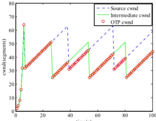
Fig. 4. Congestion window variation using an OTP
OTP: An Overlay Transport Protocol for End-to-end Congestion and Flow Control in Overlay Networks 209
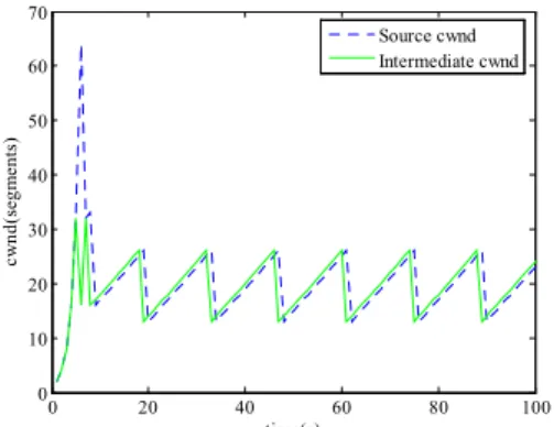
In Fig. 3 and Fig. 5, the cwnd variation when congestion control is performed not in OTP but in TCP is presented. The congestion window variation when congestion control is performed using OTP are as follows in Fig. 4 and Fig. 6.
In Fig. 3 and Fig. 5, the cwnd variation when congestion control is performed not in OTP but in TCP is presented. The congestion window variation when congestion control is performed using OTP are as follows in Fig. 4 and Fig. 6. Fig. 3 and Fig. 4 show that the cwnd variation of a source node which is determined by the intermediate buffer because the intermediate buffer is smaller than the destination buffer. Fig. 5 and Fig. 6 show that an intermediate cwnd which is determined by the destination buffer because the smaller destination buffer than the intermediate buffer has an effect like a bottleneck link.
Contrary to the scenario I, the end-to-end control using an OTP sub-layer plays an important role in determining the end-to-end cwnd variation.
Total throughput of scenario I
0 1000 2000 3000 4000 5000
not using OTP using OTP
Kbps
Source Intermediate End-to-end
0 20 40 60 80 100
0 10 20 30 40 50 60 70
time(s)
cwnd(segments)
Source cwnd Intermediate cwnd
Fig. 7. Total throughput comparison of scenario I
Total throughput of scenario II
0 1000 2000 3000 4000 5000
not using OTP using OTP
Kbps
Source Intermediate End-to-end
Fig. 5. Congestion window variation not using an OTP
0 20 40 60 80 100
0 10 20 30 40 50 60 70 80
time(s)
cwnd(segments)
Source cwnd Intermediate cwnd OTP cwnd
Fig. 8. Total throughput comparison of scenario II
The cwnd variation of a source node is influenced by the cwnd variation of an OTP. We can obtain a throughput performance and compare two network models. Total throughput and average throughput in two scenarios that are a model using an OTP and a model not using an OTP are as follows.
Fig. 6. Congestion window variation using an OTP
6. Conclusion
In this paper, we designed, simulated and validated a reliable transport protocol for overlay networks. In previous overlay networks, an end-to-end reliability is not considered also, but to mention that using TCP between two end nodes can get the end-to-end reliability in overlay networks. But, proposed mechanisms get not only a hop-by-hop reliability but also an end-to-end reliability. The end-to-end congestion and
210 전기전자학회 논문지(Journal of IKEEE) Vol. 11. No.4
flow control mechanisms are proposed to provide a reliable data transfer and improve an end-to-end throughput performance. The end-to-end congestion window variation and throughput are affected according to the intermediate and the destination buffer condition. In this work, the simulation results show that in the situation when the destination buffer is smaller than the intermediate buffer, controls using an OTP sub-layer are essential. While the latency and jitter by controls using OTP messages to provide reliable end-to-end connections might increase, total throughput comparisons with and without an OTP show performance improvements in the scenario that a source node which doesn’t know the destination buffer condition sends burst packets to the intermediate node.
[7] B. Chun, D. culler, T. Roscoe, A. Bavier, L. Peterson, M.
Wawrzoniak, and M. Bowman, “PlanetLab: An Overlay Testbed for Broad-Coverage Services,” ACM CCR, vol. 33, no.
3, Jul. 2003.
We further aim to develop the proposed mechanisms for more remarkable throughput improvements. Since this paper also doesn’t consider any delays brought about because of using OTP messages, we further aim to add more performance metrics like an average end-to-end delay or overhead brought about because of end-to-end control mechanisms. For these purposes, a specific analysis using mathematical formulas and a proof of using numerical formulas are considered to be needed.
References
[1] H. Pucha and Y. Charlie Hu, “Overlay TCP: Ending End-to-End Transport for Higher Throughput,” ACM SIGCOMM, Aug. 2005.
[2] Y. Amir and C. Danilov, “Reliable Communication in Overlay Networks,” IEEE DSN, Jun. 2003, pp. 511-520.
[3] P. Karbhari, M. Ammar, and E. Zegura, “Optimizing End-to-End Throughput for Data Transfers on an Overlay-TCP Path,” NETWORKING 2005, LNCS 3462, May. 2005, pp.
943-955.
[4] D. Andersen, H. Balakrishnan, F. Kaashoek, and R. Morris,
“Resilient Overlay Networks,” ACM SOSP, vol.35, no.5, Oct.
2001, pp. 131-145.
[5] Gu-In Kwon and John W. Byers, “ROMA: Reliable Overlay Multicast with Loosely Coupled TCP Connections,” IEEE INFOCOM, vol. 1, Mar. 2004, pp. 385-395.
[6] S. Heimlicher, R. Baumann, M. May, and B. Plattner,
“SAFT: Store And Forward Transport in Mobile Ad-hoc Networks,” Communication Systems Group, ETH Zurich, Tech.
Rep. 239, Jul. 2005.
[8] The Spines overlay network, http://www.spines.org/.
저 자 소 개
Kyung-Hoe Kim (Member)
Kyung-Hoe Kim is a Ph.D candidate in the department of electonics computer engineering in Korea University. He received the B.S., and M.S. degrees in the department of electronics engi- neering from Korea University in 2000 and 2003, respectively. His current research interests include the post-transport protocols and mobile/wireless network architecture for future Internet.
Pyoung-Yun
Pyoung-Yun Kim received his B.S. and M.S. degrees in electro- nics and computer engineering from Korea University, Seoul, Korea in 2005, and 2007, respectively. He is working as assistant engineer in DM R&D center of Samsung Electronics. His current interest is P2P overlay network and IPTV over P2P.
Sung-Kwan Youm
Sung-Kwan Youm received his B.S. degree in control instrumen- tation engineering from Hankuk University of Foreign Study in 1998. He received his M.S.
degrees and Ph.D. in electronics engineering and communication engineering from Korea University, Seoul, Korea in 2001, and 2006 respectively. He is working in
OTP: An Overlay Transport Protocol for End-to-end Congestion and Flow Control in Overlay Networks 211
Telecommunication Network Business Division at Samsung Electronics. His current interest is the call processing system of WiMax.
Seung-Joon Seok
Seung-Joon Seok received his B.S.
degree in electronics engineering from Konkuk Uni- versity, Seoul, Korea in 1997 and the M.S. and Ph. D degrees in electronics engineering from Korea University, Seoul, Korea, in 1999 and 2003, respectively. Since 2004, he has worked for computer engineering department, Kyungnam University since 2004. His research interests include quality of service model of Internet, TCP performance in wireless Internet, traffic engineering, and MAC of wireless network
Chul-Hee Kang
Chul-Hee Kang is currently a professor in the department of electronics engineering at Korea University since 1995. He is received the B.S., M.S. and Ph.D. degrees from Waseda University, Tokyo, Japan in 1975, 1977 and 1980, respectively. From 1980 to 1994, he was with Electronics and Telecommunications Research Institute (ETRI), Korea, and from 1990 to 1994, he was a vice president of ETRI. In 1994, he was a visiting professor at Washington University, USA. His current research interests include the areas of next generation Internet.