• 검색 결과가 없습니다.

A Comprehensive Study on Fuel Injector Test Bench for Heavy Duty Engine

N/A
N/A
Protected

Academic year: 2021

Share "A Comprehensive Study on Fuel Injector Test Bench for Heavy Duty Engine"

Copied!
7
0
0

로드 중.... (전체 텍스트 보기)

전체 글

(1)

A Comprehensive Study on Fuel Injector Test Bench for Heavy Duty Engine

Shubhra Kanti Das

*

, Sakda Thongchai

*

, and Ocktaeck Lim

*,†

Key Words: Heavy duty injector, Injector test bench, Injection quantity, Injection pressure

Abstract

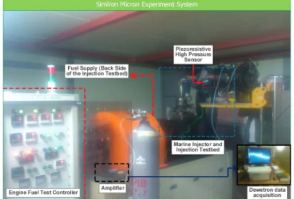
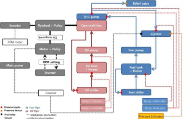
This study discusses a fuel injector test bench containing a mechanical type fuel supply system for heavy duty diesel engine. The main focus of this study was to evaluate the design stability of the test bench, which basically measures the injector durability of a multi-hole heavy duty injector by using pure diesel as a test fuel. In this experiment, diesel spray was controlled by a specially designed control box and all the experiments were carried out to measure e.g. fuel injection pressure and fuel injection quantity to understand the injection status which is interlinked with the stability factor of total test bench design. Also, the durability test was performed to understand the heavy duty operation lastingness of the designed system and the flow rate of the installed distributor pump in the fuel supply system of this studying test bench was compared with LO-1 and LO-2 pump. The results of the above mention tests revealed that the injector test bench design and control system can serve the purpose for heavy duty injector.

1. Introduction

Diesel engine plays a dominant role in the field of power, propulsion and energy. Today’s diesel engine performance, power output economy is greatly dependent on the effectiveness of the fuel injection system. The fuel on injection system has to perform the important duty of initiating and controlling the combustion process

(1)

. In the off-highway diesel engine market, the traditional injection system is also gradually replaced by the high-pressure fuel injection systems

(2)

. In the present day’s injection system of diesel engines are designed to obtain higher injection pressure

(3, 4)

. Also, the key goal to reduce the exhaust emission by increasing efficiency with the help of the

advanced injection system

(5)

. When the injection pressure will increase, the fuel particle becomes small. If the injection pressure is too high, the ignition delay period becomes shorter and hence the possibilities of homogeneous mixture reduced and eventually the combustion efficiency dropped
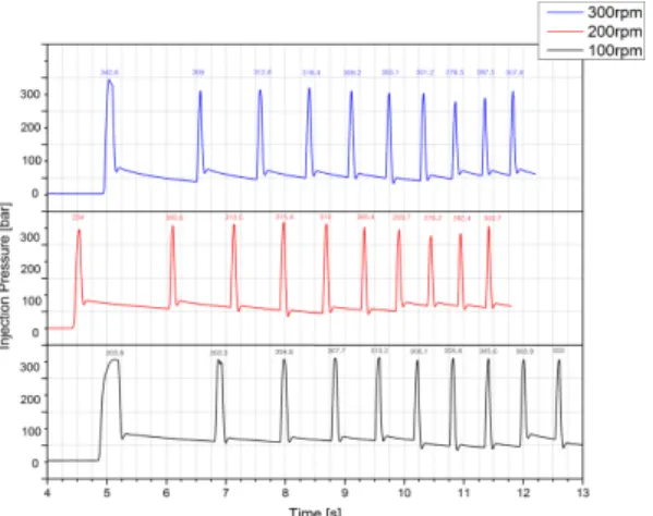
(6,7)

. For lifetime verifi- cation of an automotive components it is important to simulate injection phenomena in a test bench that certainly regenerate some more boundary conditions to understand the fuel system design which will help researchers to elevate a more stable future test bench system. Again diesel fuel spray penetration depends to a great extent on injection pressure, fuel properties, and nozzle geometry. In a mechanically controlled fuel injection system, the injection pressure increases together with increasing engine speed and load

(8)

.

For measuring the durability of a heavy duty injec- tor for heavy duty engine, a test bed was designed along with a mechanical type distributor inline fuel supply system which can be controlled by pressing the buttons of a control box. This paper aims to com-

(Recieved: 12 Sep 2015, Recieved in revised form: 29 Sep 2015, Accepted: 30 Sep 2015)

*울산대학교 대학원 기계공학과

책임저자, 회원, 울산대학교 기계공학부 E-mail: [email protected]

TEL: (052)259-2852 FAX: (052)259-1680

(2)

prehend about heavy duty engine fuel injection phe- nomenon e.g. fuel injection pressure and fuel injection quantity where the fuel was injected by manually adjusting the injector test bench and control system.

As more reliable fuel injection pressure analysis indi- cates that the test system will work appropriately with heavy duty diesel system.

2. Experimental System Overview

2.1 Injector durability test bench system The pictorial layout of the total test system is shown in Fig. 1. The total system was contained with a main test equipment, control box, a fixed injector, fuel tank and oil tank. Distributor type inline fuel supply pump and motor connection was controlled by engine fuel motor control box where both rpm and operating time can adjust. Also, a flywheel was installed with this system for smooth rotation where the flywheel was directly connected with the pump and flywheel has a cover for safety purpose. The control box can adjust the rpm of the installed motor in the main unit which also has the ability to run the test bench system either in automatic or manual mode. Control box design can control not only time, but also the operating condition as a number of revo- lutions. Injector used in this durability test was designed with fixed firm supports which make the injector more secure. Fuel from the pump is installed with main experimental equipment and fuel was sprayed through the injector where the injected fuel can collect separately. As a mechanically controlled fuel injection allowed to measure the pressure imme- diately after the pump and before the injector as well as the needle lift and fueling. Also a special cooling system was developed and attached to the test bed in order to maintain desired preset constant temperature condition. This in-line fuel injection pump was driven by a camshaft and a pumping element which mounted vertically in a straight line, side by side.

The lower half of the pump housing supports and enclose a horizontally positioned camshaft, which has so many cam profiles. Each pumping element

consists of a pump plunger which reciprocates in the barrel in depending on camshaft profile. The camshaft profile converts the angular movement of the camshaft into a linear plunger motion by the roller cam fol- lower and a plunger return spring. The fuel enters the fuel ports at a pressure up to 1.5 bar, filling the space between the plunger and delivery valve. The plunger moves up by depending on camshaft rotation follow- ing the cam profile and cuts off the feed ports.

Instantly, the in-barrel pressure collapses as fuel begins to escape down the vertical slot and exits through the feed/spill port. The pressure rise in the in-barrel results in a pressure wave traveling towards the injector. When this pressure wave reaches the injector nozzle the needle opens and the injection starts. After the fuel delivery ends, the pressure in the injector chamber falls, the needle closes, and the injection process terminates. Injection pressure is the Fig. 1 Total arrangement of injector durability test equipment

Fig. 2 Schematic diagram of test system

(3)

fuel pressure just before the injector nozzle holes and the injection pressure history should in general exhibit a high mean/peak pressure ration, i.e., no extreme pressure peaks.

The fuel and oil tank used in this experiment was separated from the main test unit. Fig. 2 shows the schematic diagram of the full test system. To control the temperature of the fuel tank and oil tank, a heater is installed. For circulating both fuel and oil, a circu- lated pump were also installed. Also for the designed test bench the theoretical expectation of injection pressure is typically about 350 bar.

2.2 Total control system

Flow chart of the total control system is given in Fig. 3 where flow chart contains a gray part which represents the control box section, red area which represents camshaft box, oil tank, chiller and blue zone represents the injection pump, injector, fuel tank and chiller. Fuel tank and oil tank also have a differ- ent flow chart. Fuel tank and chiller have a thermo- couple which was installed to control the temperature of the fuel with the help of a heater and then measure the temperature. When the fuel reached on the desired temperature, then the fuel supplied to the fuel supply pump and sprayed through the injector. Dur- ing the fuel spray the pressure was measured at injec- tor where the front end was designed to reduce the pressure through the relief valve when pressure is higher than optimum.

On the other hand, a thermocouple was also installed with an oil tank and chiller as a heating

source for getting an appropriate temperature on the basis of temperature measurement. A thermocouple was connected with each injector pump and injector fuel tank, oil tank and chiller for measuring the tem- perature. The injector was connected with a pressure sensor, pressure relief valve and a pressure gauge to measure the pressure. The motor was designed in such a way so that the rpm of the motor can be con- trolled. Also, Flywheel was attached with the experi- mental apparatus which is directly connected with motor and pulley. A speed reduction ratio of 4:1 is maintained and for safety purpose flywheel has a cover.

2.3 Spray visualization, injection quantity and injection pressure measurement

The spray visualization of this system was per- formed by black constant volume combustion bomb.

A light source was used and the spray image was taken by a high speed camera (Photron Fastcam SA3) and for measuring injected fuel quantity the poured spray amount was collected in a test beaker and measured. For the injection quantity test, the pump ran for 1 min and then the fuel supply system was automatically stopped after 1 min. In the mean- time, Piezoresistive Kristler Pressure Sensor 4067A and Amplifier were connected with the Dewetron Data acquisition platform to measure the injection pressure signal. RPM range is controlled by the con- trol box where the range can be varied from 100 rpm to 400 rpm.

3. Test & Operating Condition

Pure diesel was used in the experiment of durabil- ity measurement and diesel fuel was injected through the injector and collected in a test beaker for measur- ing the injection quantity. Experimental condition is briefly mentioned in Table 1

When the test device starts its operation the fol- lowing factor should be considered,

1. Automatic or manual option is only possible when each indicator light of the control box is ON.

Fig. 3 Injector test durability control system flowchart

(4)

2. The motor rotates when rotational light is turned on.

3. Timer operation is selected when the timer ON, counter OFF and counter operation is selected when counter OFF, timer ON and motor will operate only when the manual button is pressed.

4. Results and Discussion

4.1 Fuel flow measurement

For measuring the flow rate of the designed equip- ment, all other necessary equipment was gathered to make the flow measurement. Flow rate measurement is based on lift depth with a corresponding rack point which is related to pipe inner diameter. On the basis of rack point the flow rate was obtained and the com- parison graph was shown in Fig. 4 where the flow rate of the current fuel supply pump used in the test bench was compared with L-orange pump sample no L3240 where LO-1 and LO-2 indicates different sample of L3240 fuel pump. When rack point is 25

mm the result shows that the flow rate difference of three identical pumps is 2.5% which is almost negli- gible. When the rack point was further increased to 37.5 mm the flow rate difference among them is 3.6% which is almost similar. Finally, when the rack point is 50 mm the installed pump flow rate of the test bench was differ around 8.5% from LO-2 whether in compare to LO-1 the difference is still negligible

4.2 Method of spray visualization

A high speed camera is used to observe the charac- teristics of fuel spray for the heavy duty injector used in this study and fuel spray image were captured.

Experimental images confirmed that the highly pres- surized fuel spray appropriately inject through the injector and spray developed smoothly in all of the 13 holes. From the time interval count of the image it is clear that fuel vaporization starts from 9ms. Since this study mainly deals with an injector bench system for heavy duty engine so fuel injection pressure and fuel injection quantity was thoroughly investigated.

However Fig. 7 represents the spray visualization image which indicates about the spray pattern corre- lation with each time frame increased.

4.3 Injection quantity measurement result Fuel injection quantity was measured after the fuel injection happened for each specific rpm. Two experi- mental measurements were taken to evaluate the injection quantity. Each time the pump started within 100 to 400 rpm range and every injection quantity was measured very carefully when the fuel fume completely condensed. Since the observation was taken by human eyes so the margin of error is taken into account. From the graph it is obvious to see that margin of error is a bit high in 400 s but the overall graph from 100-300 rpm range indicates that the margin of error is not high for both experiments. In the first fuel injection quantity test the maximum quantity was 1775 mL which was measured when the rpm was 300 and the minimum quantity was 852 mL when the rpm is 100. But in second experiment 5 times measurement was taken for 400 rpm where the Table 1 Experimental and operational condition

Nozzle opening pressure 360 bar

Test time 1 minute

Injection hole specification 0.41 × 13 holes Standard of flow rate (100bar) 12,790 ml × 3%

(12,406 ml ~ 13,174 ml)

Fig. 4 Flow rate comparison of installed pump of current

test bench vs previously used pump data

(5)

overall injection quantity varies from (1610-1815) mL and minimum injection quantity in 790 mL. The difference between the average of minimum and maximum injection quantity between two experi- ments was 62 mL and 70.5 mL which is more coher- ent for a heavy duty injection system.

4.4 Fuel injection pressure measurement result Figure 8 shows the fuel injection pressure for corre- sponding time. A Piezoresistive Kristler Pressure Sensor 4067A and amplifier connected with Dew-

etron data acquisition system to measure the injection pressure. Since all the previous measurements were taken in 1 minute time frame so this fuel injection pressure investigation was performed in the same time duration. When the fuel pump was running at a speed of 100 rpm three observations was taken, when 200 rpm around two observation was taken and for 300 rpm two observation was taken. For 100 rpm number of cycle varies from 94~97 and for 200 rpm number of cycle varies from 84~85 but for 300 rpm number of cycle are more than 200. Since the Fig. 5 First fuel injection quantity test Fig. 6 Second fuel injection quantity test

Fig. 7 Visualization of fuel spray for heavy duty injector

(6)

pressure signal of each rpm is very long, so in which part where the average maximum pressure lie down that 10

th

cycle data was taken into consideration and presented in the graph. For 100 rpm, average maxi- mum injection pressure is laid on 305 bar for 200 rpm average maximum pressure lie on 330 bar but in case of 300 rpm the average maximum pressure lie on 360 bar. Since it was a bit laborious to plot the whole data. For comparing the fuel injection pressure stability of the desire injection test bench first 10 cycles were plotted. However the total cycle average maximum pressure is same for first 10 cycles and the value are 305.39. On the other hand for 200 and 300 rpm for first 10 cycles the average maximum pres- sure is 300 and 306.79 respectively. Since the aver- age maximum pressure for three different conditions didn’t go under than 300 so it can be concluded that the injection pressure signal is continuous and injec- tor test bench design is quite efficient to perform the action for heavy duty engine.

5. Conclusions

In a mechanically controlled fuel injection system, the injection pressure increases together with increas- ing engine speed and load. During the injection pro- cess, the maximum injection pressure can be more

than double of the mean pressure. It has to be pointed out that the main goal was to increase the mean injection pressure to some reasonable maxi- mum level. The maximum injection pressure is deci- sive for the mechanical loading of the fuel injection pump’s components and drive. At a higher mean injection pressure the injection duration becomes shorter, if the fuelling is kept constant. So finally in this experiment, the designed fuel supply system for injector test bench keep maintains such a qualitative and quantitative injection pressure. As to understand the fuel injection more deeply, fuel spray was inves- tigated and the spray image ensures a uniformly dis- tributed fuel injection within 13 holes. Again from quantity test, the amount was slightly fluctuated on 400 rpm condition however the flow rate test mea- surement indicate the designed fuel pump is more stable than previous. However the fuel injection pres- sure comparison denotes a more stable fuel supply system which performs more steady operation and the quantity test imply that the injected amount of fuel maintains a harmony and the margin of error is almost negligible for 100-300 rpm. However the margin of error is a bit high for 400 rpm but it doesn’t have any impact of the reliability factor of the design. With all this above information it can be concluded that the test bench design and fuel supply system is more stable to perform the operation of the heavy duty injector.

Acknowledgments

This research was financially supported by the Ministry of Education (MOE) and National Research Foundation of Korea (NRF) through the Human Resource Training Project for Regional Innovation and the Energy Efficiency & Resources (20122020100270) of the Korea Insitute of Energy Technology Evalua- tion and Planning (KETEP) grant funded by the Korea government Ministry of Trade, Industry &

Energy (MOTIE) and Business for R & D Technology Innovation funded Korea Small and Medium Business Administration in 2013 (Grants No. S2081559).

Fig. 8 Time domain injection pressure comparison for

different rpm

(7)

References

(1) A. Bakar, R. S. Ismail and A. Rahim, “The internal combustion engine diversification technology and fuel research for the future: A Review”, Proceeding of AEESEAP Regional Symposium on Engineering Edu- cation, 2007, Kuala Lumpur, Malaysia.

(2) B. Mahr, “Future and Potential of Diesel Injection Sys- tems”, Thermo- and Fluid Dynamic Processes in Die- sel Engines 2, pp 3-17, 2002.

(3) L. G. Schumacher, J. Van Gerpen, Brian T. Adams,

“Diesel Fuel Injection Pump Durability Test with Low Level Biodiesel Blends”, Paper Number: 036036 an ASAE Meeting Presentation.

(4) A. Hideyuki, H. Nishimura, Y. Ibaraki and N. Iida,

“Study of diesel spray combustion and ignition using high pressure fuel injection and a micro-hole nozzle

with a rapid compression machine: improvement of combustion using low cetane number fuel”, JSAE Review 19, pp. 319-327, 1998.

(5) W. Gui-hua, Wang, Y. Zhang-tao, Yao, L. Na and H Xuezheng, “Theoretical Study on Tolerance of Fuel Injection System of Diesel Engine”, SAE Technical Paper, 2004-01-1318.

(6) K. Kant, A. Pati, B Viswanath and R. Thiyagarajan,

“Cyclic Irregularities in Idle and Fuel Delivery Varia- tion of a Rotary Fuel Injection Pump”, SAE Technical Paper, 2004-32-0056.

(7) M. Marcic, “A new method for measuring fuel-injec- tion rate, Flow Measurement and Instrumentation”, pp.

159-165, 1999.

(8) B. Kegl, “Successive optimal design procedure applied

on conventional fuel injection equipment”, Journal of

Mechanical Design, 118(4), 490-493, 1996.

수치

Fig. 2 Schematic diagram of test system
Fig. 3 Injector test durability control system flowchart
Fig. 4 Flow rate comparison of installed pump of current test bench vs previously used pump data
Fig. 7 Visualization of fuel spray for heavy duty injector
+2

참조

관련 문서

 The Dutch physicist Pieter Zeeman showed the spectral lines emitted by atoms in a magnetic field split into multiple energy levels...  With no magnetic field to align them,

Modern Physics for Scientists and Engineers International Edition,

Koreans love animals, mountains, and people, and traditional Korean artists have shown them in their

Five days later, on 15 January 1975, the Portuguese government signed an agreement with the MPLA, FNLA and UNITA providing for Angola to receive its independence on 11

Usefulness of co-treatment with immunomodulators in patients with inflammatory bowel disease treated with scheduled infliximab maintenance therapy.. Oussalah A, Chevaux JB, Fay

Inclusion and Inclusiveness: Shared Vision of Youth for Local, National, and Global Village Inclusion at large stands for embracing populations with disabilities and

웹 표준을 지원하는 플랫폼에서 큰 수정없이 실행 가능함 패키징을 통해 다양한 기기를 위한 앱을 작성할 수 있음 네이티브 앱과

_____ culture appears to be attractive (도시의) to the