Subscript
ARC: Anti-Reflective Coating RI: Reflective Index
1. Introduction
In PV systems, about 30% of the sun’s energy normally reflected back to air after striking from the panel’s surface while 70 % of energy could be able to make its path to solar cells1). Reflection occurs when two mediums have a variable RI. So when RI of both medium is close to one another, less light will be reflected back. However, there will be no reflection if RI of coated material is the same as that of the surrounding air2-4). The more is the angle of incident light are far away from normal, the more is the light reflection5). Anti-Reflection Coating (ARC) is generally applied to those devices where light reflection is a major issue. The focal hurdle in a PV device’s fabrication is minimum conversion of energy efficiency, it can be developed by semiconductor and advanced material micro-fabrication6,7). For this purpose, the usage of ARC has been very effective to provide better transmission and to minimize reflection8). The common procedure to minimize the reflection is to coat the
substrate with the material having appropriate RI and an optimized thickness9,10). A variety of materials could be utilizes as ARC film in silicon solar cells such as Al2O3, SiO2, ZnS, TiO2, MgF2, etc. and a combination of these materials. The inappropriate selection of ARC films and partial understanding of their specification can cause an increase in reflection, a reduction in transmittance of light and hence lower the efficiency of a solar cell. In this review paper, we categorized ARC film into single and multi-layered coating.
2. Single Layered ARC
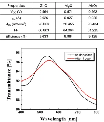
Sagar et al. investigated performance of single layered (SL) ZnO, MgO and Al2O3 material as ARC on silicon solar cell substrate after depositing using RF sputtering11). The thickness of MgO, ZnO and Al2O3 set to be 85, 95 and 80 nm respectively.
The electrical characterizations of coated films were examined by solar simulator (Sol3A Class AAA) and transmittances were measured by UV visible spectrometer (Shimadzu MPC3600).
The measured transmittance spectrum of ZnO was 95% at 412 nm, for MgO it was 92% at 373 nm and for Al2O3 it was 93% at 356 nm. Table 1 show results obtained from solar simulator.
Mahadik et al. prepared SiO2 SLARC through sol-gel process by using tetraethoxysilane (TEOS), Triton X-100 and Polyethy- leneglycol (PEG) as polymeric porogens materials12). UV spectrometer (PerkinElmer, Lamda 750) was used to measure
DOI:https://doi.org/10.21218/CPR.2020.8.1.001 eISSN 2508-125X
Impact of Anti-Reflective Coating on Silicon Solar Cell and Glass Substrate : A Brief Review
Muhammad Aleem Zahid ․ Muhammad Quddamah Khokhar ․ Eun-Chel Cho ․ Young Hyun Cho* ․ Junsin Yi*
College of Information and communication, Sungkyunkwan University, Suwon 16419, Korea
Received January 3, 2020; Revised February 10, 2020; Accepted February 14, 2020
ABSTRACT: The most important factor in enhancing the performance of an optical device is to minimize reflection and increasing transmittance of light for a broad wavelength range. The choice of appropriate coating material is crucial in decreasing reflection losses at the substrate. The purpose of this review is to highlight anti-reflection coating (ARC) materials that can be applied to silicon solar cell and glass substrate for minimizing reflection losses. The optical and electrical behavior of ARC on a substrate is highly dependent on thickness and refractive index (RI) of ARC films that are being deposited on it. The coating techniques and performance of single and multi-layered ARC films after coated on a substrate in a wide range of wavelength spectrum will be studied in the paper.
Key words: Anti-Reflection Coating, Silicon solar cell, Glass, Reflective index, Wavelength
*Corresponding author: [email protected], [email protected]
ⓒ 2020 by Korea Photovoltaic Society
This is an Open Access article distributed under the terms of the Creative Commons Attribution Non-Commercial License (http://creativecommons.org/licenses/by-nc/3.0)
which permits unrestricted non-commercial use, distribution, and reproduction in any medium, provided the original work is properly cited.
1
the transmittance at the broad band range of 300-900 nm. The coating exhibits the RI of 1.39 and for thickness of ~100 nm. The calculated transmittance at soda lime glass substrate after applying coating was observed to be 97.5% at wavelength of 500 nm. However, the coated substrate showed an increase in transmittance of about 6% in 400-600 nm wavelengths as compared to bare substrate. Attenuation in average transmittance of 0.6% was recorded after exposing the coated substrate in air as it is shown in Fig. 1.
Zhu, Li Qiang, et al. deposited Al2O3 on n-type crystalline silicon wafer by Atomic Layer Deposition (ALD) by the use of Al(CH3)3 and H2O as precursors13). They obtained average reflectance between 2.8% to 4.2% on thickness range of Al2O3
from 100 nm to 70 nm. Optical characteristics of coated Al2O3
have been investigated through spectroscopic ellipsometry.
They obtained carrier life time of about ~4.5 ms and effective surface recombination velocity of ~4 cm/s by depositing 100 nm layer of Al2O3.
Ali et al. deposited titanium dioxide (TiO2) and indium tin oxide (ITO) ARC films on p-type monocrystalline silicon cell by using radio frequency magnetron sputtering15). The width of TiO2 from 55 to 60 nm and ITO from 60 to 64 nm was used. The deposited layers on the substrate were analyzed by Raman Spectroscopy, X-ray Diffraction (XRD), Energy Dispersive
Spectroscopy (EDS), Field Emission Scanning Electron Microscopy (FESEM) and Atomic Force Microscopy (AFM).
They measured overall optical reflectance in the wavelength range of 400-1000 nm which was about 12% for ITO and 10%
for TiO2 as shown in Fig. 2. Moreover, improvements in the measurements of reflectance were observed to be 25% for ITO and 23% for TiO2 as compared to as-grown silicon.
3. Double Layered ARC
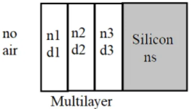
Ali et al. performed a sputtering procedure at room temper- ature for the preparation and evaluation of SLARC (SiO2) and double layered (DLARC) (SiO2/TiO2) on silicon solar cells14). They investigated the elemental analysis of SiO2 and SiO2/TiO2
by the use of EDS while surface morphology appearance was composed by FESEM. Structural diagram of SiO2 and SiO2/ TiO2 have been shown in Fig. 3.
d1 and d2 shows thickness of layers while no, n1, n2 and ns shows the RI of air, outer layers, inner layer and silicon substrate. For achieving zero reflective scenarios, the condition of the equation should be fulfilled.
Table 1. Electrical properties of coated films
Properties ZnO MgO Al2O3
VOC (V) 0.564 0.571 0.562
ISC (A) 0.026 0.027 0.026
JSC (mA/cm2) 25.656 26.455 26.484
FF 66.603 64.064 61.225
Efficiency (%) 9.633 9.864 9.125
Fig. 1. Transmittance before and after air exposure
Fig. 2. Percentage reflectivity by layers with wavelength range
Fig. 3. a) SiO2 b) SiO2/TiO2
tan
±
(1)
tan
±
(2)
It was observed that SiO2 and SiO2/TiO2 coatings show reflectance of 15% and 7% respectively for the broad band range of 400-1000 nm. Minimum reflectance of 2.3% has been shown at the wavelength of 630 nm. So, by using double layered SiO2/TiO2, 37% improvement in efficiency is recorded for mono crystalline silicon solar cell.
Dhungel. Suresh Kumar, et al. applied DLARC using MgF2
and SiNx on silicon solar cells16). They deposited 75 nm thick layer of MgF2 having RI of 1.38 over 72 nm SiNx thick film having RI of 2.05 by using thermal evaporation under high vacuum of 10-6 Torr. By using these ratios of thickness of SiNx
and MgF2 revealed meaningful performance having conversion efficiency of 16.01% for multicrystalline and 16.94% for single crystalline solar cell respectively. Fig 4 shows the effect of reflectance over SiNx with and without MgF2 film.
Jung, Jinsu, et al. successfully deposited DLARC (TiO2/ Al2O3) using sol-gel process on p type Si solar cells and annealed at 400℃17). The fabricated solar cells having DLARC achieved the efficiency of about 13.95% having an open circuit voltage (VOC) of 593.35 mV, short circuit current of 35.27 mA/cm2 and fill factor (FF) of 66.67%. Lowest reflectance showed by DLARC of about 3.02% at 970 nm. These coated films showed lower average reflectance of 4.74% in the broad- band range of 400 nm to 1000 nm. Moreover, the cell having DLARC shows relatively low value of series resistance as compared to SLARC.
Medhat, Mohamed investigated the effect of TiO2 and MgF2
as DLARC on silicon solar cell using simulations18). The output result can be seen in wavelength spectrum of 400 nm-1200 nm.
As a result, they noticed that reflectance was reduced to 30.2%
to 2.37%, short circuit current density enhanced to 38.6 mA/cm2, VOC and FF were achieved to be 0.68V and 0.84. They concluded that there was an improvement in the wavelength of 700 nm by fixing the thickness of MgF2 as 0.7(λ/4) and TiO2 as 0.78(λ/4).
Sharma, Rajinder performed the numerical calculations in order to obtain reflectance from Si3N4 as SLARC and DLARC using transfer matrix method (TMM)19). For single film the transfer matrix is as:
cos
cos
is tilted optical admittance with component represented by:
⟘=cos , for the perpendicular component.
║= ( cos), for the parallel component.
is the propagation angle through the film.
λ
πcosθ
is the phase thickness of the film.
d1 is the thickness of layer while θ1 is the diffraction angle.
For double layered the transfer function become:
cos cos
cos cos
This gives reflectance coefficients and reflectance as:
Where m11, m12, m21, m22 the elements of characteristics matrix are while are the admittance values for medium and substrate.
PCID simulator was used to investigate the reflectance of silicon solar cell. They found that reflectance reduced from
>30% to < 2% having a short circuit current of 3.86 mA/cm2. They noticed efficiency of 19.6% for single layered ARC and Fig. 4. Reflectance spectrum of single and double layered films
20.22% for double layered ARC. Furthermore, Si3N4/Si3N4 as DLARC causes in reduction of reflectance to about <10% for the broadband range of 400-1100 nm and <2% for wavelength range of 500-900 nm.
Shah, Deb Kumar, et al. created DLARC using Zinc oxide (ZnO) and silver doped ZnO material on crystalline silicon solar cell using sol-gel method which is followed by annealing at 50 0℃ for 4 hours20). They noticed considerable decrease in reflec- tance to about 7.13% in the broad band spectrum of 400 nm -1000 nm and it showed good surface property. So Ag doped ZnO could be promising DLARC on silicon solar cell with low cost.
4. Multiple Layered ARC
Sahouane et al. used MATLAB simulation to combine n1=
SiNx:H-rich silicon, n2=Silicon oxide(SiOx) and n3= oxynitride (SiOxNy) to see the behavior of effective reflectivity (Reff) for broadband range of 300-1100 nm as shown in Fig. 521). They used transfer matrix method to implement optical equations to compute results. They also calculated IQE using Silvaco and PCID software. Table 2 shows the confirmation of minimum reflectivity when SiNx:H combined with DLARC. The computed results also depict that multilayer comprising silicon nitride, silicon oxide and silicon oxynitride induces a valuable enhance- ment in photo generated current of 1.6 mA.cm-2 compared to single layer ARC. Moreover the use of SiNx:H having d3>30 and n3=2.4 can act as a good passivation and bulk layer.
Multi-layered coatings comprising of SnO2, Ta2O5, ATO, TiO2, SiO2, and ITO have been prepared through Sol-Gel Dip
coating technique22). Achieved coated films were characterized by XRD, SEM, ellipsometry and AFM. Single layered porous silica gave light transmittance of 95%. In multilayer films, after examine the relation between transmission of light and wavelength, it is found that ITO-TiO2-SiO2 films and SnO2- Ta2O5-SiO2 films gave greater light transmittance of 97.5 % and 96.2 % which is higher as compared to SL SiO2 film in the region around 300-900 nm wavelength. Thickness values of films are in the range of 30-115 nm.
Priyadarshini et al. concluded that thickness of multilayer coating plays an important part in decreasing the reflection from glass surface23). They proposed three coating materials SiO2- TiO2-ZnO arranged such that SiO2 is the first layer and ZnO is the third layer. The total thickness of all three layers fixed to about 206 nm. They described that if thickness of material obeys quarter-quarter-quarter (Q-Q-Q) and quarter-half-quarter (Q-H-Q) wavelength rule then there will be drastic decrease in reflectance spectra. This is due to fact that TiO2 have higher RI then that of first and third layer and it showed the reflectance of 0.5 – 2% in the wavelength range of 400 -700 nm. They also gave good results of reflectance and transmittance if the incident angle varies from 0 to 90˚.
Salih, Ammar et al. revealed that multi-layered Zinc Sulfide (ZnS) is a favorable and little cost ARC material for applications related to solar cells24). In this research, they successfully deposited thin films of ZnS on a glass substrate with the use of a thermal evaporation technique containing three different layers of ZnS. AFM discloses the average grain size and rough- ness drop with quantity of layers. The reflectivity of Single, double and triple layered ZnS was calculated to be 0.105, 0.095 and 0.080. The optimal outcome was establish in three layered ZnS thin film having RI of 1.79 and comparatively little reflecti- vity of about 0.080 having broad band gap of 3.697 eV.
5. Conclusion
ARC is one of the important parameter to enhance the efficiency of PV module. The increasing demand of efficient solar panel makes the researchers to explore the best ways to improve light traction. This review paper has given the investigation about ARC, which can be well suited with silicon solar cell and glass substrate in order to reduce reflection. Many researchers proved experimentally the performance of material and their impact in enhancing the transmittance in wide range of wavelength spectrum. It is concluded that multilayer ARC have Fig. 5. Three layered structure
Table 2. Effective reflectivity by varying the layers Cells
(non- encapsulated)
n1,d1
(SiOx) n2,d2
(SiOxNy) n3,d3
(SiOx:H) Reff
(%)
No ARC 34.5
Single layer 2.03 (73 nm) 11.7
Double layer 1.5 (55 nm) 2.1 (53 nm) 7.4
Triple layer 1.48 (80 nm) 2 (5 nm) 2.4 (50 nm) 4.4
more impact on decreasing the reflectance within the spectrum range as compared to single layered ARC and it is highly depen- dent on adjusting the thickness of film and RI of material.
Acknowledgments
This work was supported by Korea Energy Agency 20001795, the Korea Institute of Energy Technology Evaluation and Planning (KETEP) 20183010014270 and the Korea Institute of Energy Technology Evaluation and Planning (KETEP) 201930 10014850.
References
1. Kumaragurubaran, B., Anandhi, S., “Reduction of reflection losses in solar cell using anti-reflective coating,” International conference on computation of power, energy, information and communication ICCPEIC, 2014.
2. Keshavarz Hedayati, M., Elbahri M. , “Antireflective coatings:
Conventional stacking layers and ultrathin plasmonic meta- surfaces, a mini-review,” Materials, 9.6, 2016.
3. He, X. D., Torrance, K. E., Sillion, F. X., Greenberg, D. P. “A comprehensive physical model for light reflection,” ACM SIGGRAPH computer graphics Vol. 25, No. 4, pp. 175-186, 1991.
4. Lim, K. P., Ng, D. K., Wang, Q., “Broadband antireflection for a high-index substrate using SiNx/SiO2 by inductively coupled plasma chemical vapour deposition,” J. Phys. D Appl. Phys., 085302, 49.8, 2016.
5. Hanaei, Hengameh, M. Khalaji Assadi, and R. Saidur.,
"Highly efficient antireflective and self-cleaning coatings that incorporate carbon nanotubes (CNTs) into solar cells: A re- view”, Renewable and Sustainable Energy Reviews, Vol. 59, pp. 620-635, 2016.
6. Prevo, B. G., Hon, E. W., Velev, O. D., “Assembly and charac- terization ofvcolloid-based antireflective coatings on multi- crystalline silicon solar cells,” J. Mater. Chem., Vol. 17, pp. 791 –799, 2007.
7. Waitaa, S. M., Adudaa, B. O., Mwaboraa, J., Granqvistb, C.
G., Lindquistb, S.-E., Niklassonb, G., Hagfeldtc, A., Boschloo, G., “Electron transport and recombination in dye sensitized so- lar cells fabricated from obliquely sputtered and thermally an- nealed TiO2 films,” J. Electroanal. Chem.. Vol. 605, No. 2, pp.
151–156, 2007.
8. Maas, R., Mann, S. A., Sounas, D. L., Alu, A., Garnett, E. C., Polman,“Generalized antireflection coatings for complex bulk meta materials,” Physical Review B 195433, 93.19, 2016.
9. Kobiyama, M., “Basic theory of thin film optics (in Japanese),”
Optronics Co. Ltd., Shinjuku, Tokyo, Japan, 2002.
10. Born, M., Wolf, E. Principles of optics, 7th ed., Cambridge Univ. Press, Cambridge, U.K. p. 67, 1999.
11. Sagar, R., Asha, R., “Increasing the Silicon Solar cell efficiency with transition metal oxide nano-thin films as anti-reflection coatings,” Materials Research Express, 2020.
12. Mahadik, D. B., Lakshmi, R. V., Barshilia, H. C., “High per- formance single layer nano-porous antireflection coatings on glass by sol–gel process for solar energy applications,” Sol.
Energy Mater. Sol. Cells Vol. 140, pp. 61- 68, 2015.
13. Zhu, L. Q., Liu, Y. H., Zhang, H. L., Xiao, H., Guo, L. Q.,
“Atomic layer deposited Al2O3 films for anti-reflectance and surface passivation applications,” Applied Surface Science, Vol. 288, pp. 430-434, 2014.
14. Ali, K., Khan, S. A., Jafri., M. Z. M., “Effect of double layer (SiO2/TiO2) anti-reflective coating on silicon solar cells,” Int. J.
Electrochem. Sci, Vol. 9, pp. 7865-7874, 2014.
15. Ali, K., Khan, S. A., Jafri, M. Z. M., “Structural and optical properties of ITO/TiO2 anti-reflective films for solar cell appli- cations,” Nanoscale research letters, 9.1, 175, 2014.
16. Dhungel, S. K., Yoo, J., Kim, K., Jung, S., Ghosh, S., Yi, J.
“Double-layer antireflection coating of MgF2/SiNx for crystal- line silicon solar cells,” J. Korean Phys. Soc., Vol. 49, No. 3, pp.
885-889, 2006.
17. Jung, J., Jannat, A., Akhtar, M. S., Yang, O., “Sol–Gel Deposited Double Layer TiO2 and Al2O3 Anti-Reflection Coating for Silicon Solar Cell,” J. Nanosci. Nanotechnol., Vol.
18, No. 2, pp. 1274-1278, 2018.
18. Medhat, M., El-Zaiat, E. S., Farag, S., Youssef, G., Alkhadry, R., “Enhancing silicon solar cell efficiency with double layer antireflection coating,” Turkish Journal of Physics, Vol. 40, No. 1, pp. 30-39, 2016.
19. Sharma, R., “Silicon nitride as antireflection coating to en- hance the conversion efficiency of silicon solar cells,” Turkish Journal of Physics, Vol. 42, No. 4, pp. 350-355, 2018.
20. Shah, D. K., Han, S. Y., Akhtar, S. M., Yang, O., Kim, C. Y.,
“Effect of Ag Doping in Double Antireflection Layer on Crystalline Silicon Solar Cells,” Nanosci. Nanotechnol. Lett., Vol. 11, No. 2, pp. 159-167, 2019.
21. Sahouane, N., Abdellatif. Z., “Optimization of antireflection multilayer for industrial crystalline silicon solar cells,” Energy Procedia, Vol. 44, pp. 118-125, 2014.
22. Kesmez, Ö., Akarsu, E., Çamurlu, H. E., Yavuz, E., Akarsu, M., Arpaç, E., “Preparation and characterization of multilayer anti-reflective coatings via sol-gel process,” Ceram. Int., Vol.
44, No. 3, pp. 3183-3188, 2018.
23. Priyadarshini, B. G., Sharma, A. K., “Design of multi-layer an- ti-reflection coating for terrestrial solar panel glass,” Bulletin of Materials Science, Vol. 39, No. 3, pp. 683-689, 2016.
24. Salih, A. T., Najim, A. A., Muhi, M. A., Gbashi, K. R.
“Single-material multilayer ZnS as anti-reflective coating for so- lar cell applications,” Opt. Commun., Vol. 388, pp. 84-89, 2017.