```
1. INTRODUCTION
In order to flow high current in superconducting electric power devices many superconducting (SC) tapes have to be wound or stacked vertically or in parallel. For a case of superconducting fault current limiter (SFCL), there are representative two types of modules, a pancake type and a linear bar type [1, 2], which are non inductive. The currents in each SC wires of the modules flow parallel or anti-parallel to the neighbors, which influences each other electromagnetically and leads to ac loss change. Therefore when designing the electric power devices such as a fault current limiter, we have to consider the gap between SC wires and the direction of current flow in the SC modules.
The previous studies reveal that the ac loss was reduced for the antiparallel current flow in face to face stacks [3-5].
However, the ac loss increased for the SC-stack array when current flow of each SC tape in a column of the array was parallel to that of a SC tape at the next neighbor column and the same row, although the directions of the currents of the SC tapes in the column are antiparallel to each other. It was also dependent of the misalignment between SC tapes in the stack array. For parallel current path in a face-to-face stack, the ac loss increased. It was attributed to the phase change of the current flow in the inner and the outer wires in the stack, which resulted in the large amount of magnetic field penetration into the SC tapes [6]. In this study we
investigated ac transport current losses for anti-parallel current flow and compared the electromagnetic properties with those of the single SC tape as well as those of the same stack for the parallel current path. The gap between the SC tapes in the stack varied in order to verify the electromagnetic influence of the neighbors when current flows in opposite direction. The model was implemented in the finite element method program by the commercial software [7, 8]. We aim to understand the reason of the ac loss reduction in detail by analyzing the current distribution and the magnetic field distribution calculated numerically.
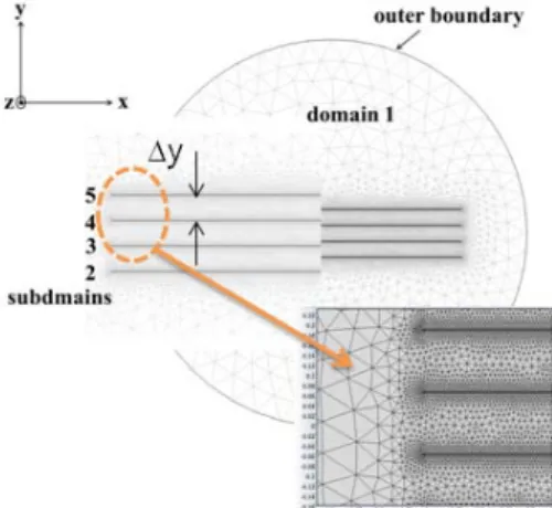
Fig. 1. The cross sectional view of the face-to-face stack of SC tapes in 2-dimensional plane.
AC transport current loss analysis for anti-parallel current flow in face-to-face stacks of superconducting tapes
Jaeun Yoo*, Young-Hee Han, Hey-Rim Kim, Byung-Jun Park, Seong-Eun Yang, Heesun Kim, Seung-Duck Yu, and Kijun Park
Future Technology Laboratory, KEPCO Research Institute, Daejeon, Korea
(Received 2April 2014; revised or reviewed 12 June 2014; accepted 13 June 2014)
Abstract
In this study we investigated ac transport current losses in the face to face stack for the anti-parallel current flow, and compared the electromagnetic properties with those of the single SC tape as well as those of the same stack for the parallel current path. The gap between the SC tapes in the stack varied in order to verify the electromagnetic influence of the neighbors when current flows in opposite direction, and the model was implemented in the finite element method program by the commercial software, COMSOL Multiphysics 4.2a. Conclusively speaking, the loss was remarkably decreased for the anti-parallel current case, which is attributed the magnetic flux compensation between the SC layers due to the opposite direction of the current flows. As the gap between SC tapes was increased, the loss mitigation became less effective. Besides, the current density distribution is very flat cross the sample width for the narrower gap case, which is believed to be benefit for the power electric system. These results are all in good agreement with those predicted theoretically for an infinite bifilar stack.
Keywords: AC Loss, superconducting tapes, FEM method, numerical simulation
* Corresponding author: [email protected]
Table 1 SAMPLE PROPERTIES [9].
Width 4 mm
SC layer thickness 2 µm
Substrate IBAD-MgO template
Jc0 at self field 2.16 MA/cm2
Fig. 2. The current Ik obtained by integrating the current density Jz(x,y) over each SC domain k = 2, 3, 4, and 5.
2. NUMERICAL SIMULATION
The sample properties and SC modeling can be found in details elsewhere [6]. The sample of SC tape has SmBa2Cu3O7-δ layer of 2 µm thickness on IBAD-MgO template, which is fabricated in Korea Electrotechnology Research Institute (KERI) [9].
The critical current density of the sample at self-field, Jc0, was 2.16×10⁶ A/cm2, which converted to critical current (Ic) of 173 A. For antiparallel current flow, the point constraint was imposed that the amount of current (Ik) obtained by integrating the Jz(x,y) over each domain k = 2, 3, 4, and 5 (see Fig.1) . That is,
=
∫
k domain
z
k t J x yt da
I
) , , ( )
( , (1) of which the amount is the same, but the sign of that is opposite to the neighbor as shown in figure 2. The current was applied as Ia =I0sin(2πft) where I0 = 0.1 ~ 0.9 Ic and f= 50 Hz (period T = 0.02 sec)
The independent variables are the x- and y- components of the magnetic field Hx, Hy in xy plane of Fig. 1. They were solved in the time-dependent partial differential equation (PDE) obtained by combining the Faraday’s law and the Ampere’s law. The final form of the PDE is
) (J -E
) (J E H
H μ μ
z z
z z y
t x
t
=
⋅
∇
+
∂
∂
0 0 0
0 0
0
0
0 (2)
The electric field is modeled by the E-J power law [5] for superconducting domain as
n
c z z
z J (B)
(x,y,t) E J
) (J
E
= 0 ,
where E0 was 10-6 V/cm, and Jz =∂xHy−∂yHx. Jc(B)
was the field dependence of current density and n was 21.
The permeability of vacuum, µ0 is 4π×10-1 Oe cm/A. For the domain1 (air), the Ohmic law, Ez = ρairJz , was applied, where ρair = 1×10⁸ Ωcm. Q is the total ac loss per cycle, that is, the sum of Qk’s which is the ac loss over SC domain k,
Q J x yt E x yt da dt
k z
k ( , , ) ( , , )
T
∫
∫
⋅= . (3)
The gap, ∆y, between SC tapes in figure 1 was 1.2 mm (∆y1) and 4.8 mm (∆y2). In this model, the half width, w, is 10 mm.
3. RESULTS AND DISCUSSION
Fig. 3 shows the normalized ac loss per cycle, f, as a function of the normalized applied current, I0/Ic, where f is
) / /(µ0Ic2 π Q
f = . It is useful to compare loss properties for SC layers having the different critical current values [10].
The loss values for the antiparallel current case are lower than others. The ac loss data of the single tape and the stack for the parallel current were obtained numerically from our previous study. The narrower the gap is, less the ac loss is generated for the antiparallel current flow case. This result agreed with the analytical solution in [4]. Especially, for the gap = ∆y1 (narrower gap case), the ac loss is almost one order of magnitude lower than those of the thin rectangle cross section case predicted in the theory [11]. From now on, we call the ∆y1 and ∆y2 for the case of the gap = ∆y1 and
∆y2 of antiparallel current path, respectively.
Fig. 4 shows the magnetic field lines around the SC stack for Ia=0.9Icsin(2πft) at the two moments: t1 = 0.02 sec and t2 = 0.025 sec. The field lines are all parallel between SC tapes for the antiparallel current as seen in figure 4(a) and (b), which is almost the same as predicted in [4]. The length of the arrows represents the log-scaled magnitude of the magnetic field. The normal component of the field appears only near the edges [5]. To the contrary, the magnetic field lines penetrate vertically all the region of the SC layers for the parallel current case seen in Fig. 4(c) and (d). It can be easily understood that the magnetic field normal to the SC tapes is canceled out in the gap between domain 2 and domain 3 due to the direction of the transport current opposite to each other. Therefore only the magnetic field parallel to SC tapes dominantly appeared.
Fig. 3. The normalized ac loss per cycle, f, as a function of the normalized applied current, I0/Ic.
Fig. 4. The magnetic field lines around the SC stack for ft)
sin(2 I 9 . 0
Ia= c π at the two moments: t1 = 0.02 sec (left) and t2 = 0.025 sec (right): (a) and (b) for ∆y1, (c) and (d) for the parallel current case.
The magnetic flux density distributions, Bz, and the corresponding current density distributions, Kz, of the SC layers in figure 5 and 6, respectively, under the conditions of t=0.025sec and I0=0.5Ic for the ∆y1 and ∆y2. The Kz(x,t) is defined by integrating Jz over thickness, as
∫
= J x yt dy t
x
Kz( , ) z( , , ) [10]. It is clearly seen that the magnetic flux rarely penetrated into the SC layers. The flux penetrated less for the inner layers than those for outers, and less for the ∆y1 than for ∆y2. Compared with the single tape and the parallel current case, the amount of the magnetic flux penetrating is almost nothing (see [6, 10, 12]).
This is attributed to the compensation of the normal component of the field as mentioned above. Only close to the edges of SC domains the normal field appeared for both for the ∆y1 and ∆y2 cases. From the Bz distribution and the critical state models, such as the Bean and the Kim models, the Kz distributions can be understood somehow; the critical current flows through the critical region where magnetic flux penetrates, and the shield current which is lower the critical current flows through the other region, that is the Meissener region. At the boundary between two regions, the Jz has peak due to the field dependence of Jc [12]. However, the penetration depth change as seen in Fig.
5 and 6, in other words, the Meissener region length (lM) (0 < x) with respect to I0 is very distinguishable from that of the single SC layer predicted in [11]. It seemed too short, compared with that of the single SC case [10]. It needed to verify whether the results are reasonable or not.
J. R. Clem et al. [4] calculated analytically the magnetic flux density distributions and current density distributions for the antiparallel current of the infinite vertical stack.
According to the analytical calculation of J. R. Clem, the ratio of lM to w is determined by
Fig. 5. The magnetic flux density distributions, Bz, under the conditions of t=0.025sec and I0=0.5Ic for the cases (a)
∆y1 and (b) ∆y2.
Fig. 6. The current density distributions, Kz, which are corresponding to Bz in figure 5.
∆
= ∆
−
=
) (
2 / )) / ( tanh(
2
) / (
, 1
2 0
k K y w
y w
I I w
l
c M
π π
α π
α
(4)
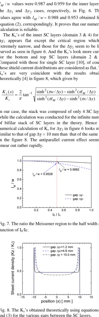
where K(k) is the complete elliptic integral of the first kind of modulus k=tanh(π(w/∆y), and w is the half width of the sample. The behavior of lM /w is illustrated in Fig. 7 for our cases, ∆y /1 w = 0.12, and ∆y /2 w= 0.48. The
w
lM / values were 0.987 and 0.959 for the inner layers of the ∆y1 and ∆y2 cases, respectively, in Fig. 6. These values agree with lM /w= 0.988 and 0.953 obtained from equation (2), correspondingly. It proves that our numerical calculation is reliable.
The Kz’s of the inner SC layers (domain 3 & 4) for the
∆y1 appears flat except the critical region which is extremely narrow, and those for the ∆y2 seem to be little curved as seen in figure 6. And the Kz’s look more curved for the bottom and top SC layers (domain 2 & 5).
Compared with those for single SC layer [10], of course, these shield current distributions are considered as flat. The Kz’s are very coincident with the results obtained theoretically [4] in figure 8, which given by
) / ( sinh ) / ( sinh
) / ( sinh ) / ( tan sinh
) 2 (
2 2
2 2
1
y x y
l
y l y
w K
x K
M
M c
z
∆
−
∆
∆
−
= − ∆
π π
π π
π . (3)
In our case, the stack was composed of only 4 SC layers, while the calculation was conducted for the infinite number of bifilar stack of SC layers in the theory. Hence our numerical calculation of Kz for ∆y2 in figure 6 looks more similar to that of gap ∆y = 10 mm than that of the same ∆y2
in the figure 8. The antiparallel current effect seems to smear out rather rapidly.
Fig. 7. The ratio the Meissener region to the half width as a function of I0/Ic.
Fig. 8. The Kz’s obtained theoretically using equations (2) and (3) for the various gaps between the SC layers.
The Kz’s tell us the reduction of the ac losses for the antiparallel current case. It can be considered that the Jz is dominant near the surfaces for the thin strip geometry, and then, Jz ≈Kz/(d/2). When Jz is greater than Jc(B) Ez increases according to the nth power law of the E-J relation.
The Kz/Kc values are uniform and very lower than the unity over the most of the region.
4. SUMMARY
In this study we investigated ac transport current losses for the antiparallel current, and compared the electro- magnetic properties with those of the single SC tape as well as those of the same stack for the parallel current path. For the comparison with the case of the parallel current flow we used the same SC modeling for the motive sample in [7], and the model was implemented in the finite element method program by the commercial software. The ac loss was remarkably decreased for the anti-parallel current case, which is attributed the magnetic flux compensation due to the opposite direction of current flows of the neighbors.
This was easily understood by magnetic field lines near each SC wire; almost the magnetic field lines are parallel to the SC wire surfaces. Hence, as the gap between SC tapes was increased, the loss mitigation became less effective.
Besides, the Kz/Kc(B) and the penetration depth behavior were also figured out by compared with the theoretical results [4]. The magnetic flux rarely penetrated into the SC tape, which is very distinguishable from the parallel current case.
ACKNOWLEDGMENT
This work was supported by a grant from the Power Generation and Electricity Delivery Program of the Korea Institute of Energy Technology Evaluation and Planning (KETEP) funded by the Korean government, Ministry of Trade, Industry and Energy.
REFERENCES
[1] J. Souc, F. Gomory and M. Vojeneiak, “Coated conductor arrangement for reduced AC losses in a resistive-type superconducting fault current limiter,” Supercond. Sci. Technol., Vol.25, no.11, pp. 014005, Jan. 2012.
[2] W. S. Kim et al., “AC loss dependency on the arrangement of the HTS wires in the current limiting module for SFCL,” Progress in Superconductivity and Cryogenics, vol.14, no.3, pp.9-12, Sep.
2012.
[3] M. Majoros, L. Ye, A. M. Campbell, T. A. Coombs, M. D.
Sumption and E. W. Collings, “Modeling of transport AC losses in superconduting arrays carrying anti-parallel current,” IEEE Trans.
Appl. Supercond., vol.17, No.2, pp. 1803-1806, Jun. 2007.
[4] J. R. Clem, “Field and current distributions and AC losses in a bifilar stack of superconducting strips,” Phys. Rev. B., vol. 77, no.
13, pp.134506, Apr. 2008.
[5] D. N. Nguyen, F. Grilli. S. P. Ashworth, and J. O. Willis, “AC loss study of antiparallel connected YBCO coated conductors,”
Supercond. Sci. Technol., vol. 22, no. 5, pp. 055014, May 2009.
[6] Jaeun Yoo, Dojun Youm, and SangSoo Oh, " AC Transport Current Loss analysis for a face-to-face stack of superconducting tapes,"
Progress in Superconductivity and Cryogenics, vol. 15, no. 2, pp.
34~38, 2013.
[7] Z. Hong, A. M. Campbell, T. A. Commbs, “Numerical solution of critical state in superconductivity by finite element software,”
Supercond. Sci. Technol., Vol. 19, pp. 1246-1252, 2006.
[8] COMSOL Multiphysics 3.5a Model library/ AC DC module / general industrial application / superconducting wire.
H. S. Ha, H. S. Kim, S. S. Oh, D. Youm, S. H. Moon, "Fabrication and property of round shape wire using coated conductors", International workshop on coated conductors for applications (CCA2010), Fukuoka, Japan, O-E11, Oct. 27-30 2010.
[9] E. Brandt and M. Indemn, “Type-II-superconductor strip with current in a perpendicular magnetic field,” Phys. Rev. B., vol. 48, pp.
12893-12906, 1993.
[10] W. T. Norris, “Calculation of hysteresis losses in hard superconductors and edges of thin sheets,” J. Phys. D, vol. 3, pp.
489-507, 1970.
[11] J. Yoo, J. Lee, S-M Lee, Y-H Jung, D. Youm and S. S. Oh, “Current redistribution of a current carrying superconducting tape in a perpendicular magnetic field,” Supercond. Sci. Technol., vol. 22, no. 12, pp. 125019, Dec. 2009.
![Table 1 S AMPLE PROPERTIES [9].](https://thumb-ap.123doks.com/thumbv2/123dokinfo/5237759.624123/2.892.121.773.112.1170/table-s-ample-properties.webp)