• 검색 결과가 없습니다.

Fabrication of wide-bandgap β-Cu(In,Ga)3 Se 5 thin films and their application to solar cells

N/A
N/A
Protected

Academic year: 2021

Share "Fabrication of wide-bandgap β-Cu(In,Ga)3 Se 5 thin films and their application to solar cells"

Copied!
6
0
0

로드 중.... (전체 텍스트 보기)

전체 글

(1)

Nomenlature

α-CIGS : Cu(In,Ga)Se

2

β-CIGS : Cu(In,Ga)

3

Se

5

V

oc

: open cirduit voltage, V J

sc

: short circuit current, mA/cm

2

FF : fill factor

η : conversion efficiency, %

substript

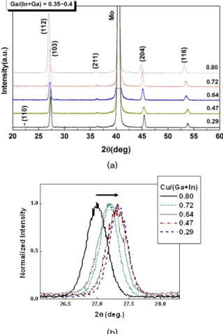
XRD : x-ray diffraction

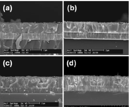
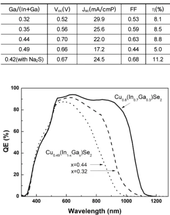
SEM : scanning electron micorscopy AES : Auger electron spectroscopy QE : quantum efficiency

LTPL : low temperature photoluminescence

1. Introduction

Chalcopyrite Cu(In,Ga)Se

2

( α-CIGS) and related films are gaining considerable interest for photovoltaic devices since their high optical absorption coefficient and adjustable band gap can enable to achieve a high conversion efficiency in α-CIGS solar cells. Technical advances in α-CIGS solar cells involving the co-evaporation of Cu, In, Ga, and Se elements through a three-stage process have reached the highest efficiency of over 20% in thin film solar cells

1)

. Solar cells with α-CIGS film show the highest efficiency with a relatively narrow band gap energy of 1.2 eV, which is below the optimum value of 1.4 eV. As the band gap of absorber materials increases, the open circuit voltage of cells deviates from being expected, resulting in the lower efficiency from theoretical values

2)

.

Recently, a tandem structure is proposed to improve the efficiency above 25%. In the structure, top cell consists of wide band gap light absorber and bottom cell consists of narrow band gap light absorber. The efficiency is high enough for bottom cell with band gap 1.0 eV. But a wide band gap absorber for top cell has not been developed yet. The purpose of our work is to find a light absorber applicable to top cell in the tandem structure.

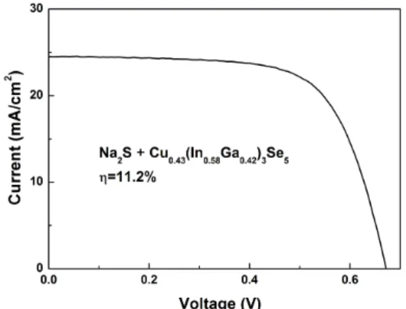
Fabrication of wide ‐bandgap β‐Cu(In,Ga) 3 Se 5 thin films and their application to solar cells

Ji Hye Kim

1)

․ Young Min Shin

1)

․ Seung Tae Kim

1)

․ HyukSang Kwon

1)

․ Byung Tae Ahn

1)

*

1)

Department of Materials Science and Engineering, Korea Advanced Institute of Science and Technology, Daejeon 305-701, Korea

ABSTRACT: Cu(In,Ga)

3

Se

5

is a candidate material for the top cell of Cu(In,Ga)Se

2

tandem cells. This phase is often found at the surface of the Cu(In,Ga)Se

2

film during Cu(In,Ga)Se

2

cell fabrication, and plays a positive role in Cu(In,Ga)Se

2

cell performance. However, the exact properties of the Cu(In,Ga)

3

Se

5

film have not been extensively studied yet. In this work, Cu(In,Ga)

3

Se

5

films were fabricated on Mo ‐ coated soda ‐lime glass substrates by a three‐stage co‐evaporation process. The Cu content in the film was controlled by varying the deposition time of each stage. X‐ray diffraction and Raman spectroscopy analyses showed that, even though the stoichiometric Cu/(In+Ga) ratio is 0.25, Cu(In,Ga)

3

Se

5

is easily formed in a wide range of Cu content as long as the Cu/(In+Ga) ratio is held below 0.5. The optical band gap of Cu

0.3

(In

0.65

Ga

0.35

)

3

Se

5

composition was found to be 1.35eV. As the Cu/(In+Ga) ratio was decreased further below 0.5, the grain size became smaller and the band gap increased. Unlike the Cu(In,Ga)Se

2

solar cell, an external supply of Na with Na

2

S deposition further increased the cell efficiency of the Cu(In,Ga)

3

Se

5

solar cell, indicating that more Na is necessary, in addition to the Na supply from the soda lime glass, to suppress deep level defects in the Cu(In,Ga)

3

Se

5

film. The cell efficiency of CdS/Cu(In,Ga)

3

Se

5

was improved from 8.8 to 11.2% by incorporating Na with Na

2

S deposition on the CIGS film. The fill factor was significantly improved by the Na incorporation, due to a decrease of deep ‐level defects.

Key words: Cu(In,Ga)

3

Se

5

, β-CIGS, external Na supply, wide-band gap absorber, deep level defects

*Corresponding author: [email protected]

Received March 28, 2013; Revised April 9, 2013;

Accepted April 18 2013

ⓒ 2013 by Korea Photovoltaic Society

This is an Open Access article distributed under the terms of the Creative Commons Attribution Non-Commercial License (http://creativecommons.org/licenses/by-nc/3.0)

which permits unrestricted non-commercial use, distribution, and reproduction in any medium, provided the original work is properly cited.

38

(2)

Ga or S, suggesting that this material has a potential for top cell.

Even though there were a few early work reported, the β -CIGS film has not been well characterized yet

6)

. It is worthwhile to revisit the film for efficiency improvement of the cell with β -CIGS film for the purpose of tandem cells and for higher efficiency in single junction α-CIGS solar cells. In this research, β-CIGS films were prepared by three-stage co-evaporation process and the photovoltaic properties of CdS/ β-CIGS cell were investigated by controlling the Ga content and by adding supplying more Na from Na

2

S source.

2. Experimental

CIGS films were grown on a Mo-costed soda-lime glass substrate by the three-stage co-evaporation process. In the first stage, an (In,Ga)

2

Se

3

film was deposited at 350

o

C by co- evaporating In, Ga and Se. In the second stage, the substrate temperature was elevated to 550

o

C in 5 min and Cu and Se were co-evaporated. At this stage, a CIGS film was formed in situ by interaction of the (In,Ga)

2

Se

3

film and the evaporated Cu and Se.

In the third stage, In, Cu, and Se sources were co-evaporated on the CIGS films. The overall composition was controlled by adjusting the deposition time and evaporation rates.

The thickness of the film was about 2 μm. The CIGS films were characterized using XRD, Raman spectroscopy, AES, and SEM. UV-spectroscopy measurements were performed to verify optical transmittance of films deposited in glass substrates.

Defects in CIGS film were analyzed by LTPL at 10K.

Solar cells with ZnO/CdS/ β-CIGS structure were fabricated on a Mo-coated soda-lime glass substrate. The Mo back contact layer with a thickness of 1 μm was deposited by dc magnetron sputtering. The CdS buffer layer with a thickness of 50 nm was deposited by chemical bath deposition. The ZnO window layer was deposited by rf magnetron sputtering and it consisted of

similar, it is not easy to distinguish β-CIGS phase from α-CIGS phase. However the (112) peak moves to larger angle as the Cu content decreases as shown in Fig. 1(b). When the Cu content is below 0.47, the (112) peak is fixed and does not increase where β-CIGS phase is formed. Moreover when the content is 0.29, an additional (110) peak appears, corresponding to β-CIGS phase

7, 8)

. Even though the In and Ga contents are large in the β-CIGS film, no secondary phase such as In

2

Se

3

or Ga

2

Se

3

exists. The structure of the compound is a tetragonal and a polycrystalline with (112) preferred orientation.

(a)

(b)

Fig. 1. XRD patterns (a) and (112) peaks (b) of Cu(In,Ga)Se

films with various Cu contents.

(3)

The α-CIGS and β-CIGS phases are more clearly distinguished in Raman spectroscopy as shown in Fig. 2. When the Cu contents is below 0.5, the β-CIGS phase is clearly dominant. Apparently a small amount of β-CIGS phase exists in the α-CIGS film with the Cu content of above 0.5.

The effects of the Cu content on the microstructure of CIGS thin film are shown in cross sectional SEM images (Fig. 3). As the Cu contents decreases, the grain size in the film after the third stage became smaller. In the plane-view SEM images, faceted and tightly connected grains are grown on the surface.

The effects of the Cu content on the microstructure of CIGS thin film are shown in cross sectional SEM images (Fig. 3). As the Cu contents decreases, the grain size in the film after the 3

rd

stage became smaller. In the plane-view SEM images, faceted and tightly connected grains are grown on the surface.

Fig. 4 is the AES depth profile of the β-CIGS film with

Cu

0.33

(In

0.65

Ga

0.35

)

3

Se

5

composition. Each element is uniformly distributed in the film, which indicates β-CIGS phase was formed through the entire depth of the film by the three-stage co-evaporation process. Also we confirmed that the film does not have multi-phases but a single phase.

The optical transmittance of the CIGS thin film with various Cu contents ranging from 0.8 to 0.3 is shown in Fig. 5. The absorption edges of CIGS thin films with lower Cu contents move to shorter wavelength and also exhibit higher transmittance in long wavelength region. Two different absorption edges are clearly seen with various Cu contents. Also the high transmittance in the long wavelength region is higher in β-CIGS film, which is desirable for tandem structure because bottom cell should absorb more long wavelength lights.

Absorption coefficients were determined by measuring both the transmittance and reflectivity of the Cu(In,Ga)Se films. The (ah v)

2

of a β-CIGS film plotted as a function of photon-energy Fig. 2. Raman spectroscopy of Cu(In,Ga)Se films with various

Cu contents. The A1 modes of Cu(In,Ga)

3

Se

5

and Cu (In,Ga)Se2 are clearly distinguishable.

Fig. 3. SEM morphologies of Cu(InGa)Se films with the Cu content of (a)0.72, (b)0.64, (c)0.47, (d)0.30.

Fig. 4. AES depth profile of Cu(In,Ga)3Se5 film.

Fig. 5. Optical transmittance of Cu(In,Ga)Se films with various

Cu contents and Ga/(Ga+In)=0.35. Two different absorp-

tion edges are clearly seen.

(4)

(h v) in Fig. 6 showed a straight-line. It indicates that the optical absorption of β-CIGS phase occurs by a direct band gap transi- tion. The band gap was estimated to 1.35 eV from extrapolating intercept. On the other hand, the E

g

does not change significantly while the transmittance greatly increases when the Cu content changes from 0.8 to 0.3. The higher optical transmittance might be due to less light scattering of In and Ga atoms compared to Cu atoms, indicating that it is useful for top cell of tandem cells.

Fig. 7 shows the illuminated J-V curves of CdS/β-CIGS solar cells with various Ga contents in the area of 0.44cm

2

. The Cu/(In+Ga) ratio was about 0.49. The conversion efficiency increased from 8.1% to 8.8% as the Ga/(In+Ga) ratio increases from 0.31 to 0.44. However, the efficiency was significantly lowered by further increase of the Ga content. As the Ga content increased the short circuit current was lowered and the open circuit voltage was increased as expected except Ga/(In+Ga)=

0.49. The photovoltaic parameters such as V

oc

, J

sc

, FF, and η are summarized in Table 1.

The increase of Ga in the CIGS film increases the band gap and may reduce defect concentrations, according previous reports.

9)

However, too much addition of Ga always showed an adverse effect.

The reason of adverse effect was due to poor morphology with too small grains and probably due to the formation of Ga

Cu

antisite which is assumed to be a deep-level trap center.

Fig. 8 shows the spectral quantum efficiency (QE) of β-CIGS solar cells with Ga contents of 0.35 and 0.44. For comparison the QE of α-CIGS solar cell with a Cu(In

0.70

Ga

0.30

)Se

2

composition was added. The cut-off wavelength shifted to shorter wavelengths due to different band gap from α-CIGS to β-CIGS.

The band gap of β-CIGS cell with Ga content of 0.44 is increased to 1.4 eV, estimated from the cut-off wavelength. The increase of QE value of the β-CIGS near the cut-off wavelength is rather slow compared to that of α-CIGS cell.

Even though we used soda-lime glass as a substrate, the role of sodium in the β-CIGS cell should be more clearly addressed.

For the purpose, sodium was further supplied into β-CIGS film by the thermal deposition of Na

2

S on Mo film or on CIGS film during the film preparation. The small amount of sodium into the CIGS absorber layer leads beneficial effects on performance

Fig. 8. Spectral quantum efficiency of CIGS solar cells.

Fig. 6. Variation of (ahv)

2

of Cu(In,Ga)

3

Se

5

film as a function of photon energy (hv).

Fig. 7. Illuminated J-V characteristics of solar cells fabricated

using the CIGS-based films.

(5)

of solar cell devices

10)

. The improved conversion efficiencies mainly by enhancing the fill factor and open circuit voltage of the devices

11, 12)

, or increased p-type conductivity observed for sodium containing devices

12, 13)

.

Fig. 9 shows a J-V curves of β-CIGS solar cells fabricated by adding an Na

2

S layer on CIGS film where Cu/(In+Ga)=0.43 and Ga/(In+Ga)=0.42. The conversion efficiency was improved from 8.8% to 11.2% by adding Na in CIGS with Na

2

S. The percent of conversion efficiency increase is as much as 27%. In the cell with Na external doping, V

oc

, J

sc

, and FF are 0.67 V, 24.49 mA/cm

2

, and 0.68, respectively, for an active layer of 0.44 cm

2

. Note that the FF is greatly increased from 0.63 to 0.68, compared to FF values in Table 1. We still have more room to improve it, up to 0.78. So far the record efficiency of β-CIGS cell is 12.2% by AGU team

6)

.

Fig. 10 shows the external quantum efficiencies measured for solar cells using CIGS-based absorber layers without and with Na

2

S. The cut-off wavelength in the near-infrared regions does not shift. In the wavelength region from 550 to 900 nm the QE

value increases successively for the sample with Na

2

S incorpora- tion. The result suggest that the diffusion length of excess carrier is larger, probably due to the suppression of In

Cu

and Ga

Cu

antisites defects by Na incorporation.

We found that the resistivity of the CIGS film without Na external supply rapidly increased as the Cu/(In+Ga) ratio decreased. However, it was observed that the resistivity was decreased by the supply of Na with Na

2

S. It suggests that the presence of Na suppressed the formation of donor type defects such as In

Cu

and Ga

Cu

antisites, resulting in the decrease of charge compensating by the deep level defect and leading to higher hole concentration in β-CIGS film.

Fig. 11 shows the LTPL spectra of β-CIGS films without and with Na

2

S incorporation. The three emissions peaks are observed at the energy of 1.24 (#1) and 1.19 (#2), and 1.08eV (#3). The #3 emission peak is likely originated from deep level defect, probably due to antisites such as In

Cu

or Ga

Cu

. However, the exact indentification of defects is not a simple task at the moment. However, note that the intensity of peak #3, that is originated form deep level defects, was substantially reduced by Na

2

S incorporation. The explanation of point defects in the film is not well understood yet and it is beyond the scope of this paper.

Even though the efficiency of β-CIGS cell is much smaller than that of α-CIGS cell, our results provide important informa- tion. The efficiency could be improved by reducing the deep level defects with external Na incorporation. The resistance of the film is lowered and the FF was improved. We believe that the performance of solar cell will be further improved by reducing the deep level defects by careful design of process conditions and band structure at the CdS/ β-CIGS interface.

Fig. 11. LTPL of Cu(In,Ga)

3

Se

5

films without and with Na

2

S incorporation.

Fig. 9. Illuminated J-V curves of Cu(In,Ga)3Se5 solar cell fabricated by adding an Na2S film on CIGS film.

Fig. 10. Spectral quantum efficiency of Cu(In,Ga)

3

Se

5

solar

cells with and without Na

2

S incorporation.

(6)

supplying external supply of Na using Na

2

S deposition. The incorporation of Na reduced the LTPL intensity of deep level defects, resulting in the decrease of resistivity of Cu(In.Ga)

3

Se

5

film. To improve the cell efficiency further, it is necessary to reduce deep level defects and design an optimum band structure at the CdS/Cu(In.Ga)

3

Se

5

interface.

Acknowledgment

This work was financially supported by the Center for Inorganic Photovoltaic Materials (No. 2012-0001167), and the Priority Research Center Program (2011-0031407), funded by the Korea Ministry of Education, Science, and Technology.

References

1. P. Jackson, D. Hariskos, E. Lotter, S. Paetel, R. Wuerz, R.

Menner, W. Wischmann, M. Powalla, “New world record effi- ciency for Cu(In,Ga)Se

2

thin-film solar cells beyond 20%”, Prog. Photovolt: Res. Appl., Vol. 19, pp. 894 –897, 2011.

2. M. Gloeckler, J.R. Sites, “Efficiency limitations for wide-band- gap chalcopyrite solar cells”, Thin Solid Films, Vol. 480-481, pp. 241-245, 2005.

14th EU-PVSEC, pp. 2143, 1997.

7. M. A. Contreras, H. Wiesner, J. Tuttle, K. Ramanathan, R.

Noufi,“Issues on the chalcopyrite/defect-chalcopyrite junction model for high-efficiency Cu(In,Ga)Se

2

solar cells”, Sol. Energ.

Mater. Sol. Cells, Vol. 49, pp. 239-247, 1997.

8. E. Schmid, M. Ruckh, F. Grunwald, and H.W. Schock,

“Chalcopyrite/defect chalcopyrite heterojunctions on the basis of CuInSe2”, J. Appl. Phys., Vol. 73, No. 6, pp. 2902, 1993.

9. G. Hanna, A. Jasenek, U. Rau, H.W. Schock, “Influence of the Ga-content on the bulk defect densities of Cu(In,Ga)Se

2

”, Thin Solid Films, Vol. 387, pp. 71-73, 2001.

10. J. Hedstrom, M. Bodegard, A. Kylner, L. Stolt, D. Hariskos, and H. W. Schock, “ZnO/CdS/Cu(In,Ga)Se

2

thin film solar cells with improved performance”, Proceedings of the 23rd IEEE –PVSC, pp. 364, 1993.

11. M. A. Contreras, B. Egaas, P. Dippo, J. Webb, J. Granada, K.

Ramanathan, S. Ashher, A. Swartzlander, and R. Noufi, “On the role of Na and modifications to CIGS absorber materials us- ing Thin MF (M=Na,K,Cs) precursor layers”, Proceedings of 26th IEEE-PVSC, pp. 359-362, 1997.

12. K. Granath, M. Bodegard, and L. Stolt, “The effect of NaF on Cu(In, Ga)Se

2

Thin film solar cells”, Sol. Energy Mater. Sol.

Cells, Vol. 60, pp. 279-293, 2000.

13. M. Ruckh, D. Schmid, M. Kaiser, R. Schaffler, T. Walter, and

H.W. Schock, “Influence of substrates on the electrical proper-

ties of Cu(In,Ga)Se

2

thin films”, Proceedings of 1st WCPEC,

pp.156-159, 1994.

수치

Fig. 1. XRD patterns (a) and (112) peaks (b) of Cu(In,Ga)Se  films with various Cu contents.
Fig. 5. Optical transmittance of Cu(In,Ga)Se films with various  Cu contents and Ga/(Ga+In)=0.35
Fig. 8. Spectral quantum efficiency of CIGS solar cells.
Fig. 9 shows a J-V curves of β-CIGS solar cells fabricated by  adding an Na 2 S layer on CIGS film where Cu/(In+Ga)=0.43 and  Ga/(In+Ga)=0.42

참조

관련 문서

In this study, thermal efficiency of a flat-plate solar collector and a U-tube solar collector using a CuO nanofluid and water as a working fluid was investigated according to

The data are corrected for temperature error due to solar radiation and the effect of low temperature on the anerod capsule and curvature of the surface of

co-treatment with hispidulin and TGF-β up-regulated the protein of expression E-cadherin and occludin against TGF-β-induced in MCF-7 and HCC38 cells.. The

Lee, “Effective Ag Doping by He-Ne Laser Exposure to Improve the Electrical and the Optical Properties of CdTe Thin Films for Heterostructured Thin Film

Laser-induced doping of amorphous copper diselenide (α-CuSe 2 ) thin film with gallium (Ga) and indium (In) was performed to control/improve their electrical

The laser-induced doping of Al into CdTe thin films is very simple and effective to dope a multilayered thin film solar cell with a relatively short

synthesis and application of silicon nano particles for improved efficiency in perovksite solar cells.. synthesis and application of silicon nano particles for improved

This study deals with the collection of solar energy and its storage in all-glass solar vacuum tubes for different types of header design, flow passage