보조공동을 이용한 초음속 공동내부의 압력진동 저감에 관한 연구
신춘식* ․ 정준창** ․ Abhilash Suryan* ․ 김희동***
A Study on the Reduction of Supersonic Cavity Pressure Oscillations Using a Sub-Cavity System
Choon Sik Shin* ․ June Chang Jeong** ․ Abhilash Suryan* ․ Heuy Dong Kim***
ABSTRACT
Numerical computations were carried out to analyze the effect of a sub-cavity at several inlet Mach numbers on the control of cavity-induced pressure oscillations in two-dimensional supersonic flow. The present passive control method, the sub-cavity applied to the front wall of a square cavity, was studied for the inlet Mach numbers of 1.50, 1.83 and 2.50. The results show that the sub-cavity is effective in reducing the oscillations, and a resultant amount of the reduction depended on the inlet Mach number, the length of flat plate, and the depth of sub-cavity used as an oscillation suppressor.
초 록
2차원 초음속 공동유동에서 발생하는 압력진동을 제어하기 위한 목적으로, 본 연구에서는 수치해석 적 연구를 수행하였다. 본 계산에서는 압력진동을 제어하기 위하여 보조공동의 형상을 변화시켰으며, 유동의 마하수를 1.50, 1.83 그리고 2.50로 변화시켰다. 그 결과, 보조공동은 압력진동을 상당히 감소시 켰으며, 압력진동의 제어효과는 유동의 마하수와 보조공동의 상세형상에 크게 의존함을 알았다.
Key Words: Compressible flow(압축성 유동), Supersonic cavity(초음속 공동), Pressure oscillations (압력진동), Passive control(피동제어), Shock wave(충격파)
†2009년 3월 18일 접수 ~ 2009년 8월 27일 심사완료
* 학생회원, 안동대학교 기계공학과
** 정회원, 국방기술품질원
*** 종신회원, 안동대학교 기계공학과 연락저자, E-mail: [email protected]
1. Introduction
The supersonic flow past a cavity induces complex flow characteristics such as vortices, flow-induced acoustic resonance, shock wave boundary layer interactions, etc. resulting in large pressure oscillations that may create
many undesirable effects in supersonic aircraft, space shuttles and air breathing propulsion systems. These pressure oscillations may lead to an increase in aircraft noise and drag, cause severe structural vibrations and fatigue on the aircraft or rocket structure, damage the vital flight instrumentation, and adversely affect the performance and stability. Hence the study of cavity flow fields and the control of the pressure oscillations are very significant for supersonic propulsion. The control of
cavity-induced oscillations has been studied by many researchers [1-7], but a practical mean of effective control in a wide range of flow conditions have not been established yet.
The oscillations can be suppressed by either active or passive control. Passive control methods are simpler and inexpensive relatively, and these involve, in general, a minor modification of cavity geometry in order to suppress the oscillations. Heller and Bliss [4] suggested that oscillations could be controlled by slanting the trailing edge of cavity. Shaw et al. [5] conducted wind tunnel tests with cavities installed in an aircraft model to assess the leading-edge saw tooth suppressor and slanted trailing edges. The slanted trailing edge was found to be effective in attenuating cavity tones but the leading-edge spoilers were not fully successful.
Sarno and Franke [6] studied static and oscillating fences, and found that the static fences were effective in suppressing cavity pressure levels. Alam et al. [7] studied a sub-cavity at Mach number 1.83 experimentally, and showed that the sub-cavity was very effective in reducing pressure oscillations. However the method was not proved on various flow conditions.
In the present study, the effectiveness of sub-cavities on the supersonic cavity flow control has been investigated on not only sub-cavity configurations but also flow Mach numbers, using a CFD method. The validation of the present CFD code is also given with some of theoretical and experimental results.
2. CFD Analysis
The governing equations are the unsteady compressible Navier-Stokes equations coupled with turbulence kinetic energy and eddy viscosity equations for modeling the turbulence
[8-10]. A TVD finite difference scheme of 3rd order with MUSCL and a 2nd order-central difference scheme are used for the spatial discretization of non-viscous terms and the viscous terms, respectively. A second-order fractional step is employed for time integration. Fig. 1 shows the grids and computational domain for the cavity. Height of main flow section above the cavity is 24 mm.
Depth and the length of the cavity are the same and equal to 12 mm. The ratios of the length of the flat plate to the depth of the cavity are / = 0, -0.125, -0.1875 and -0.25, and the ratio of the lip thickness to the depth of the baseline cavity is / = 0.05. Ratios of the depth of sub-cavity to the depth of the baseline cavity are / = 0.25, 0.30, 0.35, 0.45, 0.65, 0.70 and 0.75 in the simulations. S1 in Fig. 1(b) denotes measuring position of static pressure. Grid size is 200×80 in the region of the nozzle and 50×60 in the cavity. Dry air is used as a working gas and
(a) Computational grids (Unit: mm)
(b) Details of cavity configuration Fig. 1 Computational domain
assumed to be thermally and calorically perfect. Pressure p0 in the reservoir is 101.3 kPa. Inlet Mach number inlet at entrance of the cavity is 1.50, 1.83 and 2.50. The Reynolds number is 2.1×10⁵. No-slip and no heat transfer boundary conditions were applied on the walls. Fixed conditions were set for the inflow. Zero order extrapolation was used at the outflow.
3. Results and Discussion
3.1 Baseline Case (cavity without control)
The validity of the present computational code was studied by comparing the results of present simulation ( = 1.0, = 0,
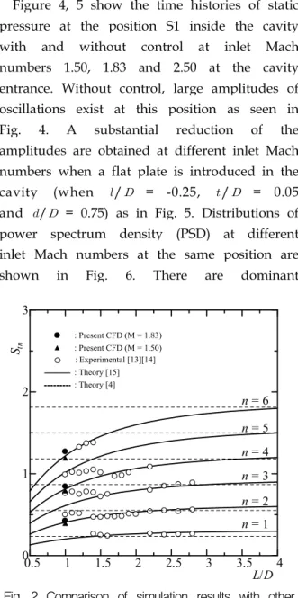
= 1.0, = 1.83, 1.50) with those of previous studies. Fig. 2 shows a comparison of the Strouhal numbers (normalized frequency: fL/U∞). Here the symbol n refers to mode number. It indicates the number of peak frequencies that appear in the diagram of distribution of power spectrum density. The compared results show a good agreement with experimental [13][14] and theoretical results [4][15], and it implies that the present code is appropriate to simulate such flow physics.
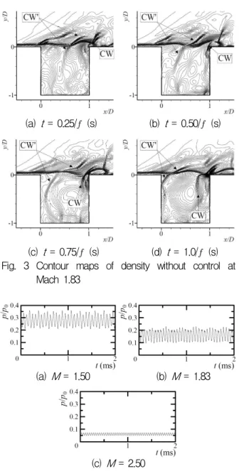
Figure 3 shows contour maps of density during one period of flow oscillation for the cavity without control at Mach number 1.83.
Here, represents the dominant frequency, which is equal to 17.5 kHz (see Fig. 6(b)). It was observed that a compression wave (CW) from the trailing edge of the cavity moves upstream as time proceeds. The upstream compression waves impinge on the cavity leading edge (Fig. 3(d)) and disturb the shear layer. This disturbance regenerates instability waves in the shear layer. While the shear layer reattaches at the rear wall of the cavity, generation of compression waves (CW) occurs
due to the impingement of instability waves on the wall as shown in Fig. 3(b) and thus completing the formation of feedback loop which is widely believed to be the reason for intense pressure oscillations. Contour maps of density in case of inlet Mach number 1.50 and 2.50 also showed similar wave interactions.
3.2 Effect of Leading Edge Plate on the Cavity Flowfield
Figure 4, 5 show the time histories of static pressure at the position S1 inside the cavity with and without control at inlet Mach numbers 1.50, 1.83 and 2.50 at the cavity entrance. Without control, large amplitudes of oscillations exist at this position as seen in Fig. 4. A substantial reduction of the amplitudes are obtained at different inlet Mach numbers when a flat plate is introduced in the cavity (when / = -0.25, / = 0.05 and / = 0.75) as in Fig. 5. Distributions of power spectrum density (PSD) at different inlet Mach numbers at the same position are shown in Fig. 6. There are dominant
L/D Stn
n = 1 n = 2 n = 3 n = 4 n = 5 n = 6
0.5 1 1.5 2 2.5 3 3.5 4
0 1 2 3
: Present CFD (M = 1.50) : Present CFD (M = 1.83)
: Theory [15]
: Theory [4]
: Experimental [13][14]
Fig. 2 Comparison of simulation results with other experimental and theoretical results
(a) t = 0.25/ (s) (b) t = 0.50/ (s)
(c) t = 0.75/ (s) (d) t = 1.0/ (s) Fig. 3 Contour maps of density without control at
Mach 1.83
(a) M= 1.50 (b) M= 1.83
(c) M = 2.50
Fig. 4 Time histories of static pressure without control
(a) M= 1.50 (b) M= 1.83
(c) M = 2.50
Fig. 5 Time histories of static pressure with control
frequencies at 15.8 kHz, 17.5 kHz and 24 kHz in case of cavity without control at Mach 1.50, 1.83 and 2.50, respectively (Fig. 6), whereas there are almost no peak frequencies for cases with control at Mach number 1.83 and 2.50 as shown in Fig. 7(b) and Fig. 7(c) (when / = -0.25, / = 0.05 and / = 0.75). In case of Mach number 1.50 at the cavity entrance there is a weak peak frequency for case with control (see Fig. 7(a). The formation of feedback loops and consequently the occurrence of resonance are considered to be the reason of intense pressure oscillations observed in the cavity without control as shown in Fig. 4, 6.
Significant reductions in oscillations (Fig. 5, 7) are due to the fact that the upstream compression waves that impinge on the front
(a) M= 1.50 (b) M= 1.83
(c) M= 2.50
Fig. 6 Distributions of PSD without control
(a) M= 1.50 (b) M= 1.83
(c) M= 2.50
Fig. 7 Distributions of PSD with control
wall and below the flat plate cannot disturb the shear layer immediately after the reflection. The reflected waves which are now below the flat plate and traveling downstream become weaker gradually as they travel and will be dissipated.
3.3 Effect of Length of the Plate
To determine the effect of length of the leading edge plate on the cavity-induced pressure oscillations, observations were also made on the cavity with / = 0, -0.125, -0.1875 and -0.25. Maximum reduction of oscillations was obtained with / = -0.25 [7].
3.4 Sub-Cavity as an Oscillation Suppressor
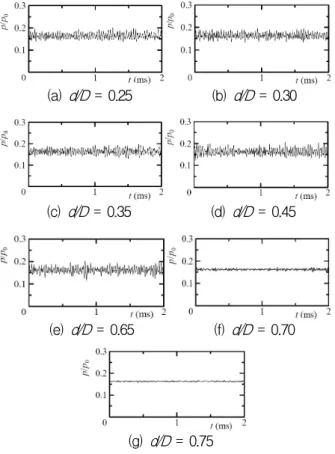
Figure 8 shows the time histories of static pressure at the position S1 on the trailing
(a) d/D= 0.25 (b) d/D= 0.30
(c) d/D= 0.35 (d) d/D= 0.45
(e) d/D= 0.65 (f) d/D= 0.70
(g) d/D= 0.75
Fig. 8 Time histories of static pressure at S1 (l/D = -0.25, t/D= 0.05, M= 1.83)
edge of the cavity of / = -0.25, / = 0.05 with the variation of the depth of sub-cavity at the front wall at inlet Mach number 1.83.
As seen from Fig. 8(a) ∼ 8(e), amplitudes of oscillations are larger than those in Fig. 8(f) and 8(g). Distributions of PSD also showed that there was no peak frequency at a relatively higher depth of sub-cavity and there were some peak frequencies at a relatively smaller depth of sub-cavity. A sub-cavity acts as an additional cavity with / > 2 for the case shown in Fig. 8(a) ∼ 8(e). In addition to the reflections of upcoming compression waves on the front wall, reflections will also occur at the bottom face of the upper cavity. These secondary reflections will reach the shear layer to excite it. However, increasing the depth of sub-cavity will reduce the aspect ratio of the upper cavity and the possibility of disturbances of shear layer by the secondary reflections will be reduced [12]. Fig. 9 shows typical density contours for the cavity without control at Mach 1.83. No upstream compression waves or the reflected waves are observed as shown in Fig. 9(a) to 9(d). Hence a stable shear layer exists in the cavity with control. Fig. 10 shows the streamlines of flow field with control (/ = -0.25, / = 0.05, / = 0.75 and = 1.83). Fig. 10 shows that another large vortex is developing in the sub-cavity which is obstructed by the leading edge plate. Therefore, shedding of small vortices is prevented in the cavity with control and there exists a stable shear layer.
3.5 Effect of Mach Number
Figure 4 shows the time histories of static pressure at the position S1 on the trailing edge of the cavity without control at inlet Mach numbers 1.50, 1.83 and 2.50 at the cavity entrance. Amplitudes of oscillations of
the static pressure variation are high in all the cases of different inlet Mach number without control and the magnitudes of mean static pressure vary with the variation of inlet Mach number. Amplitudes of oscillations are reduced
(a) t = 0.25/ (s) (b) t = 0.50/ (s)
(c) t= 0.75/ (s) (d) t = 1.0/ (s) Fig. 9 Contour maps of density with control at Mach
1.83
(a) t = 0.25/ (s) (b) t = 0.50/ (s)
(c) t= 0.75/ (s) (d) t = 1.0/ (s) Fig. 10 Streamlines with control at Mach 1.83
with the application of control device (Sub-cavity) in all the cases of different inlet Mach numbers as shown in Fig. 5. Fig. 6 shows the distributions of PSD without control at Mach numbers 1.50, 1.83 and 2.50 at the cavity entrance. There are dominant peak frequencies in all the cases of different inlet Mach numbers as shown in Fig. 6(a) to 6(c). It is seen that oscillation frequency varies with the variation of inlet Mach number. There is no peak frequency for cases with control at Mach numbers 1.83 and 2.50 as shown in Fig.
7(b), 7(c). However, there is a small peak at Mach number 1.50 as shown in Fig. 7(a).
4. Conclusion
A computational study has been carried out for supersonic cavity flows with a sub-cavity at the Mach numbers of 1.50, 1.83 and 2.50 at the cavity entrance to investigate the effectiveness of controlling cavity-induced pressure oscillations generated in two-dimensional supersonic flows. The technique is basically leading-edge control and the manipulation of shear layer development.
The results showed that the sub-cavity attached near the front wall of a square cavity was very effective in the range of inlet Mach numbers tested in reducing cavity-induced pressure oscillations. Against the main vortical flow inside a main cavity, another large vortex structure develops in the sub-cavity which is obstructed by the leading edge plate. In this situation, shedding of small vortices is prevented in the cavity with control and there exists a stable shear layer. The reduction of pressure oscillations was dependent on the inlet Mach number and the dimensions of the sub-cavity used as oscillation suppressor.
Therefore, the control device proposed may be an effective tool in the reduction of cavity tones in a wide range of flow conditions.
Acknowledgement
This work was supported by the Korea Research Foundation Grant funded by the Korean Government (MOEHRD) (KRF - 2007 - 521 - D00060)
References
1. Krishnamurty, K., "Acoustic Radiation from two Dimensional Rectangular Cutouts in Aerodynamic Surfaces," NACA TN-3487, August 1955
2. Roshko, A., "Some Measurements of Flow in a Rectangular Cutout," NACA TN-3488, 1955
3. Rossiter, J. E., "Wind-Tunnel Experiments on the Flow over Rectangular Cavities at Subsonic and Transonic Speeds,"
Aeronautical Research Council RM-3438, 1964 4. Heller, H. H., Bliss, D. B., "The Physical
Mechanism of Flow-Induced Pressure Fluctuations in Cavities and Concepts for their Suppression," AIAA Paper 75-491, 1975
5. Shaw, L., Clark, R., Talmadge, D., "F-111 Generic Weapons Bay Acoustic Environment," Journal of Aircraft, Vol.25, No.2, 1988, pp.147-153
6. Sarno, R., Franke, M., "Suppression of Flow-induced Pressure Oscillations in Cavities," Journal of Aircraft, Vol.31, No.1, 1994, pp.90-96
7. Alam, M. M., Matsuo, S., Teramoto, K., Setoguchi, T. and Kim, H. D., "A New Method of Controlling Cavity-Induced
Pressure Oscillations Using Sub-Cavity,"
Proceedings, 5th Asian-Pacific Conference on Aerospace Technology and Science, Guilin, China, CD-ROM, 2006
8. Goldberg, U. C., "Toward a Pointwise Turbulence Model for Wall-bounded and Free Shear Flows," Trans ASME, Journal of Fluids Engineering, Vol.116, 1994, pp.72-76 9. Goldberg, U. C., "Exploring a
Three-equation R-k-ε Turbulence Model,"
Trans ASME, Journal of Fluids Engineering, Vol.118, 1996, pp.795-799 10. Heiler, M., "Instationäre Phänomene in
Homogen/Heterogen Kondensierenden Düsenund Turbinenströmungen,"
Dissertation, Fakultät für Maschinenbau, Universität Karlsruhe, Germany, 1999 11. Yee, H. C., "A Class of High-resolution
Explicit and Implicit Shock Capturing Methods," NASA TM-89464, 1989
12. Tam, C. K. W., Block, P. J. W., "On the Tones and Pressure Oscillations Induced by Flow over Rectangular Cavities," Journal of Fluid Mechanics, Vol.89, 1978
13. Zhang, X., Edwards, J. A., “An Investigation of Supersonic Oscillatory Cavity Flows driven by Thick Shear,”
Aeronautical Journal, 1990, pp.355-364 14. Takakura, Y., Suzuki, T., Higashino, F.,
Yoshida, M., “Numerical Study on Supersonic Internal Cavity Flows : What causes the Pressure Fluctuations?,” 37th AIAA Aerospace Science Meeting &
Exhibit, AIAA Paper, 99-0545, 1999
15. Nishioka, M., Asai, T., Sakaue, S., Shirai, K., "Some Thoughts on the Mechanism of Supersonic Cavity Flow Oscillation, Part 2 A New Formula for the Oscillation Frequency," Journal of Japan Society of Fluid Mechanics, Vol.21, 2002, pp.368-378