†To whom corresponding should be addressed.
Department of Mechanical & Automotive Engineering, Induk University, 12 Choansan-ro, Nowon-gu, Seoul 139-749, Korea.
Tel : 02-950-7545 E-mail : [email protected]
http://dx.doi.org/10.5855/ENERGY.2015.24.4.217
Simulation and Prediction on the Performance of a Hydrogen Engine
Sung Bin Han
Department of Mechanical & Automotive Engineering, Induk University
(Received 5 November 2015, Revised 11 December 2015, Accepted 15 December 2015)
요 약
Abstract - A computer simulation has been developed to predict and investigate the performance of the assumed hydrogen engine. The simulation has be come a powerful tool as it saves time and also economical when compared to experimental study. The effects of various parameters, such as equivalent ratio, spark advance, revolutions per minute were calculated and then the optimal parameters of assumed engine were determined. The effects of spark advance, revolutions per minute, cylinder pressure, rate of pressure rise, flame temperature, rate of heat release, and mass fraction burned were simulated. The objective of the research paper is to develop a internal combustion model with hydrogen as a fuel.
Key words : Simulation, thermodynamic engine model, spark advance, engine speed, cylinder pressure
1. Introduction
Motor vehicles emit large quantities of carbon monoxide, hydrocarbons, nitrogen oxides and such toxic substances like fine particles. Each one of these can cause adverse effects on human health and environment. Because of this rapid growing rate in vehicle population in the world and the high emis- sion rates from these vehicles, serious air pollution problems have become an increasingly common phe- nomenon in modern life [1].
The unique combustion characteristics of hydro- gen that allow clean and efficient operation at low engine loads present difficulties at high engine loads.
Here, the low ignition energies of hydrogen-air mix- tures cause frequent unscheduled combustion events, and high combustion temperatures of mixtures closer to the stoichiometric composition lead to increased
nitric oxides production. Both effects, in practical application, limit the power densities of hydrogen internal combustion engines. The recent research thrust and progress on this front is the development of advanced hydrogen engines with improved power densities and reduced nitric oxides emissions at high engine loads [2].
The cost of a hydrogen engine is much less than a fuel cell and the power system of a vehicle, though fuel cells have a higher efficiency than hydrogen engines. Internal combustion engines can be fuelled by hydrogen if its structure gets a slight change. The working process is basically the same as other en- gines of the conventional fuels. Some difficulties pe- culiar to the hydrogen engines’ combustion should be overcome before the engines go into a common use, such as detonation, backfire and abnormal combus- tion, etc. With the help of a suitable mathematical model, the parameter calculation will begin and the performance of a hydrogen engine could be simulated. At last, it is possible to determine a bene- ficial working range for optimizing and predicting the engine’s performance [3,4]
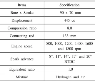
Items Specification Bore x Stroke 90 x 70 mm
Displacement 445 cc
Compression ratio 8.0 Connecting rod 133 mm
Engine speed 800, 1000, 1200, 1400, 1600 and 1800 rpm
Spark advance 8°, 11°, 14°, 17° and 20°
BTDC Equivalent ratio 1.0
Mixture Hydrogen and air Table 1. Calculation condition for simulation.
Hydrogen can be easily ignited and the flame speed is about nine times that of gasoline. Simula- tion of internal combustion engines are desirable be- cause of the aid they provide in design in predicting the trends than are normally obtainable from the experiment. It also reduces the time involved for the experimental investigation and the cost involved [5,6].
A computer simulation has been developed to pre- dict and investigate the performance of a hydrogen engine. The effects of various parameters, such as equivalent ratio, spark advance, revolutions per mi- nute were calculated and then the optimal parame- ters of assumed engine were determined. The ob- jective of the research paper is to develop a internal combustion model with hydrogen as a fuel.
2. Computer simulation
Thermodynamic engine model is based on the first law of thermodynamics expressed as [5, 7-11]:
Pressure is calculated from the equation:
The total volume of the gases inside the cylinder at a particular crank angle is given by the ex- pression:
sin
The heat release rate is given by:
⋅
In the model, heat from combustion is supplied using a Wiebe function:
Exp
Exp
3. Results and Discussion
For the computer simulation, Table 1 is shown the assumed engine conditions.
Figure 1 shows the cylinder temperature in the as- sumed hydrogen spark ignition engine as a function of crank angle according to the various spark advances. The cylinder temperature from this ther- modynamics model shows that it is shown the peak temperature about 4100℃ at 7BTDC, 800rpm, and compression ratio 8.0 and the peak temperature about 4200℃ at 9BTDC, 800rpm, and compression ratio 8.0. And the cylinder temperature from this thermodynamics model shows that it is the peak temperature about 4450℃ at 11BTDC and 13BTDC, 800rpm, and compression ratio 8.0 respectively.
Fig. 1. Variation of cylinder temperature versus crank angle.
Fig. 4. Variation of rate of heat release versus crank angle.
Fig. 2. Variation of cylinder pressure versus crank angle.
Fig. 3. Variation of rate of pressure rise versus crank angle.
Figure 2 shows the cylinder pressure in a hydro- gen spark ignition as a function of crank angle ac- cording to the various spark advances. The cylinder pressure from this thermodynamics model shows that it is the peak pressure about 103kg/cm2 at 7BTDC, 800rpm, and compression ratio 8.0 and the peak pressure about 105kg/cm2 at 9BTDC, 800rpm, and compression ratio 8.0. And the cylinder pressure from this thermodynamics model shows that it is the peak cylinder pressure about 110kg/cm2 at 11BTDC and 13BTDC, 800rpm, and compression ratio 8.0 respectively.
Figure 3 shows the rate of pressure rise in the as- sumed hydrogen spark ignition as a function of crank angle according to the various spark advances.
The rate of pressure rise from this simulation shows that it is the peak rate of pressure rise about 21kg/cm2/deg at 11BTDC, 800rpm, and compression
ratio 8.0.
Figure 4 shows the rate of heat release of the as- sumed hydrogen spark ignition as a function of crank angle according to the various spark advan- ces. The rate of heat release from this simulation shows that the peak rate of pressure rise is about 2.7cal/deg at 11BTDC, 800rpm, and compression ra- tio 8.0.
Figure 5 shows the mass fraction burned in a spark ignition for the assumed hydrogen spark igni- tion engine as a function of crank angle according to the various spark advances. From this figure, the mass fraction burned at 11BTDC and 13BTDC show a kind of fast burn results. And the period of 10%~90% mass burned was shortened about 2 de- gree at 13BTDC as compared with 11BTDC.
Figure 6 shows the cylinder temperature in the as- sumed hydrogen spark ignition engine as a function
Fig. 7. Variation of cylinder pressure versus crank angle.
Fig. 8. Variation of rate of pressure rise versus crank angle.
Fig. 6. Variation of cylinder temperature versus crank angle.
Fig. 5. Variation of mass fraction burned versus crank angle.
of crank angle according to the various revolutions per minute. The cylinder temperature from this ther- modynamics model shows that it is shown the peak temperature about 4680℃ at 17BTDC, 1600rpm, and compression ratio 8.0 and the peak temperature about 4600℃ at 20BTDC, 1800rpm, and compres- sion ratio 8.0. And the cylinder temperature from this thermodynamics model shows that it is the peak temperature about 4500℃ at 11BTDC and 1200rpm, and 14BTDC and 1400rpm respectively.
Figure 7 shows the cylinder pressure in a hydro- gen spark ignition as a function of crank angle ac- cording to the various revolutions per minute. The cylinder pressure from this thermodynamics model shows that it is the peak pressure about 120kg/cm2 at 17BTDC and 1600rpm, and 20BTDC and 1800rpm respectively. And the peak pressure at 8BTDC, 1000rpm and compression ratio 8.0 shows about
105kg/cm2.
Figure 8 shows the rate of pressure rise in the as- sumed hydrogen spark ignition as a function of crank angle according to the various revolutions per minute. The rate of pressure rise from this simu- lation shows that it is the peak rate of pressure rise about 21kg/cm2/deg at 11BTDC, 800rpm, and com- pression ratio 8.0.
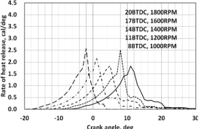
Figure 9 shows the rate of heat release of the as- sumed hydrogen spark ignition as a function of crank angle according to the various revolution per minute. The rate of heat release from the simulation shows that the peak rate of pressure rise is about 2.5cal/deg at 11BTDC, 1200rpm, and compression ratio 8.0. And at the 20BTDC, 1800rpm, and com- pression ratio 8.0 the rate of heat release from the simulation shows is about 2.6cal/deg.
Figure 10 shows the mass fraction burned in a
Fig. 9. Variation of rate of heat release versus crank angle.
Fig. 10. Variation of mass fraction burned versus crank angle.
spark ignition for the assumed hydrogen spark igni- tion engine as a function of crank angle according to the various revolutions per minute. From this figure, the mass fraction burned at 11BTDC and 13BTDC show a kind of fast burn results. And the period of 10%~90% mass burned was shortened about 4 de- gree at 20BTDC and 1800rpm as compared with at 17BTDC and 1600rpm, 14BTDC and 1400rpm, 11BTDC and 1200rpm, and 8BTDC and 1000rpm.
4. Conclusions
A computer simulation has been developed to pre- dict and investigate the performance of the assumed hydrogen engine.
According to the simulation and analysis, the re- markable conclusion shows that spark advance, com-
pression ratio, revolutions per minute, etc have a great effect on the cylinder temperature, cylinder pressure, rate of pressure rise, rate of heat release and mass fraction burned.
The effects of various parameters, such as equiv- alent ratio, spark advance, revolutions per minute were calculated and then the optimal parameters of assumed engine were determined. The effects of spark advance, revolutions per minute, cylinder pres- sure, rate of pressure rise, flame temperature, rate of heat release, and mass fraction burned were simulated.
Nomenclature
D diameter of piston h heat transfer coefficient k specific heat ratio m mass of mixture P gas pressure Q heat of the gases R universal gas constant r crank radius
T temperature θ crank angle
∆ combustion duration
subscripts
b burned
u unburned
o start of combustion
References
1. Yamin, J. A. A, Gupta, H. N, Bansal, B. B. and Srivastava, O. N, Effect of combustion duration on the performance anc emission characteristics of a spark ignition engine using hydrogen as a fuel, International Journal of Hydrogen Energy, Vol.25, pp.581-589, 2000.
2. White, C. M., Steeper, R. R. and Lutz, A. E, International Journal of Hydrogen Energy, Vol.31, pp.1292-1305, 2006.
3. Jorach, R., Development of a low-NOx truck hy- drogen with high specific power output, Interna- tional Journal of Hydrogen Energy, Vol.22, pp.423-427, 1997.
4. Ma, J., Su, Y., Zhou, Y. and Zhang, Z., Simula- tion and prediction on the performance of a vehi- cle's hydrogen engine, International Journal of Hydrogen Energy, Vol.28, pp.77-83, 2003.
5. Sakthinathan, G. P. and Jeyachandran, K., The- oretical and experimental validation of hydrogen fueled spark ignition engine, Thermal Science, Vol.14, No.4, pp.989-1000, 2010.
6. Choi, G. H, Chung, Y. J. and Han, S. B, Perfor- mance and emissions characteristics of a hydro- gen enriched LPG internal combustion engine at 1400rpm, International Journal of Hydrogen Energy, Vol.30, pp.77-82, 2005.
7. Heywood, J. B., Internal Combustion Engine Fundamentals, Mc-Graw Hill, 1987.
8. Han, S. B, A study on the prediction of hydrogen vehicle by the thermodynamic properties, Journal of Energy Engineering, Vol.24, pp.79-83, 2015.
9. Han, S. B, Combustion characteristics of hydro- gen by the thermodynamic properties analysis, Journal of Energy Engineering, Vol.24, No.2, pp.84-90, 2015.
10. Han, S. B, Theoretical analysis of a spark igni- tion engine by the thermodynamic engine mod- el, Vol.24, No.3, pp.55-60, 2015.
11. Han, S. B, Effect of compression ratio on the combustion characteristics of a thermodynamics based homogeneous charge compression ignition engine, Vol.24, No.3, pp.61-66, 2015.